Szabolcs Lőrincz
-
It's alive!
12/31/2018 at 17:36 • 0 commentsAnd so, my Christmas tree has came to life. It's not the neatest work (it's called 'ugly soldering' for a reason), but I did it, and learned some things about high voltage, which is great. Here's a short video showing off how it works.
I could watch this for hours.
-
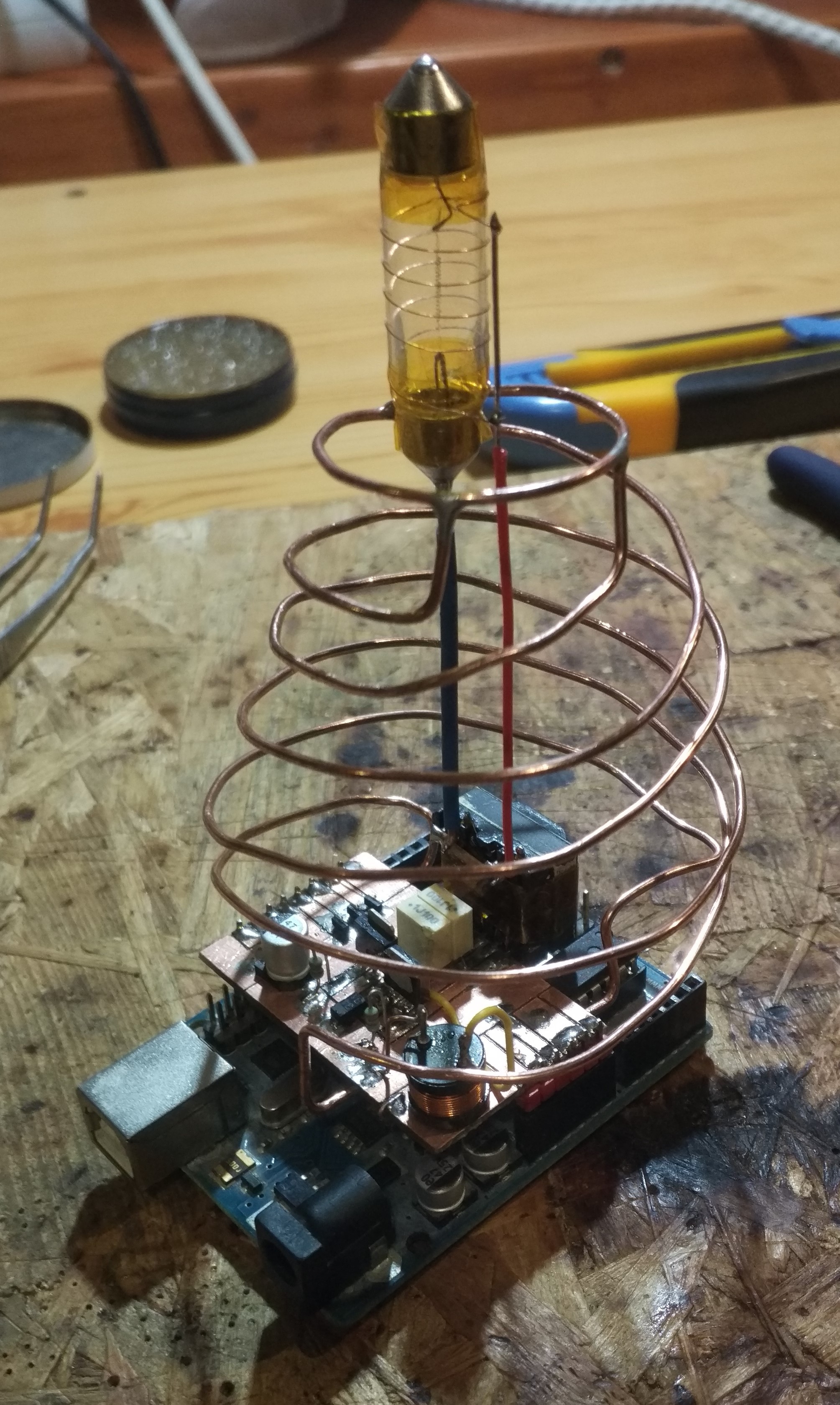
Putting the tree on the ornament
12/31/2018 at 17:31 • 0 commentsNow for the last step: the tree. The obvious choice was to make it from copper. I used standard 1.5 mm^2 MCU wire, which I stripped from its insulation. I soldered it to the underside of the board, so that it will also serve as the ground connection for the LEDs.
![]() ---------- more ----------
---------- more ----------After putting 2 coils of wire, I decided that another coil was needed. Indeed, it looks better with 3 coils. Time to hang the lights! (Or more likely, solder.) I soldered SMD LEDs in series with 1k resistors to form the lights, and soldered them directly to the tree. To connect to the supply, I used colorful wires for additional decorations. This turned out to be a nightmare, as bending these relatively rigid wires to position often resulted in pads breaking off the soldered LEDs and resistors, meaning I had to replace them. The wires were only cut at the first and last LEDs, at the intermediate pieces I just cut the insulation and pulled it slightly aside, exposing the copper conductor. This way, it could be soldered neatly.
![]()
I also improvised a rig to solder the LEDs and resistors together:
![]()
In this picture you can see (more or less) how it works: you attach one end of a component to the copper, and then solder the other component directly to it. Then, after desoldering from the copper plate, it could be added to the tree. After soldering all 6 string to their place, I connected their lower ends to the Arduino IO ports. Since all LEDs draw approximately 2-3 mA, the AVR is able to supply 10 LEDs directly from the GPIO. I also covered the lights with hot glue for more structural stability. As it turned out, this was also a great way to diffuse their light.
The rest is pretty much just software. You can see the final result in the project pictures, and in the video in the next log.
-
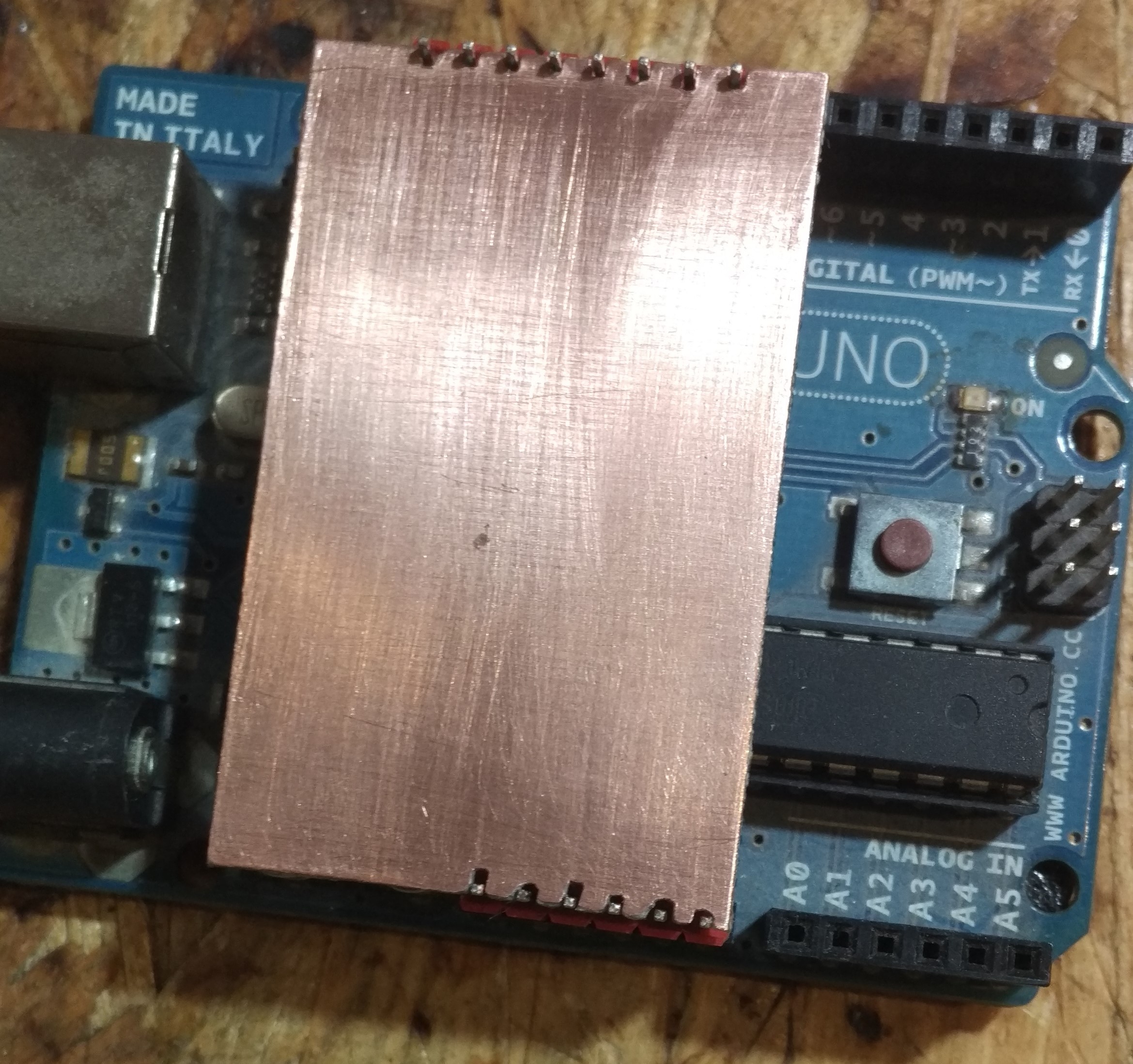
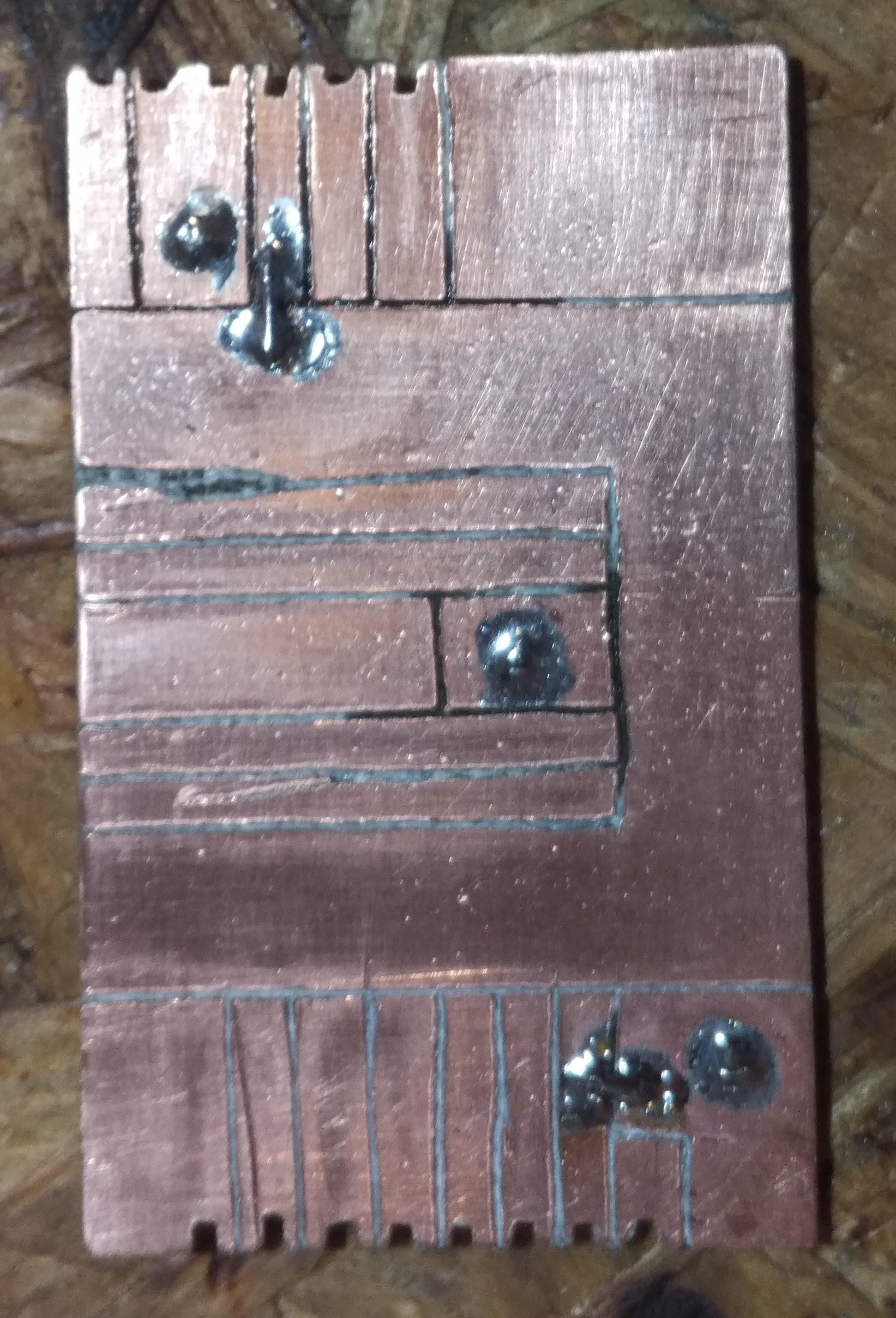
Assemble
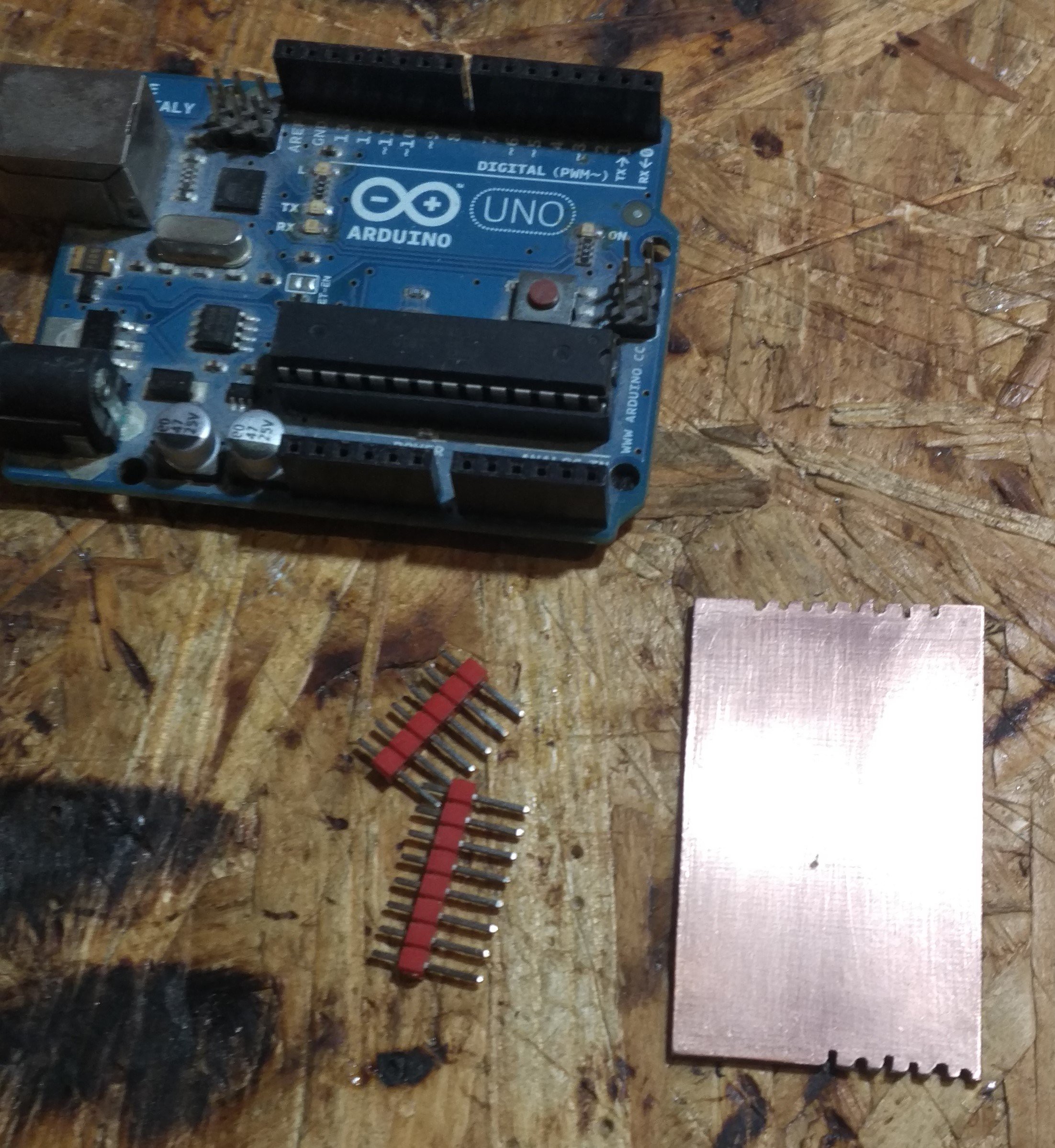
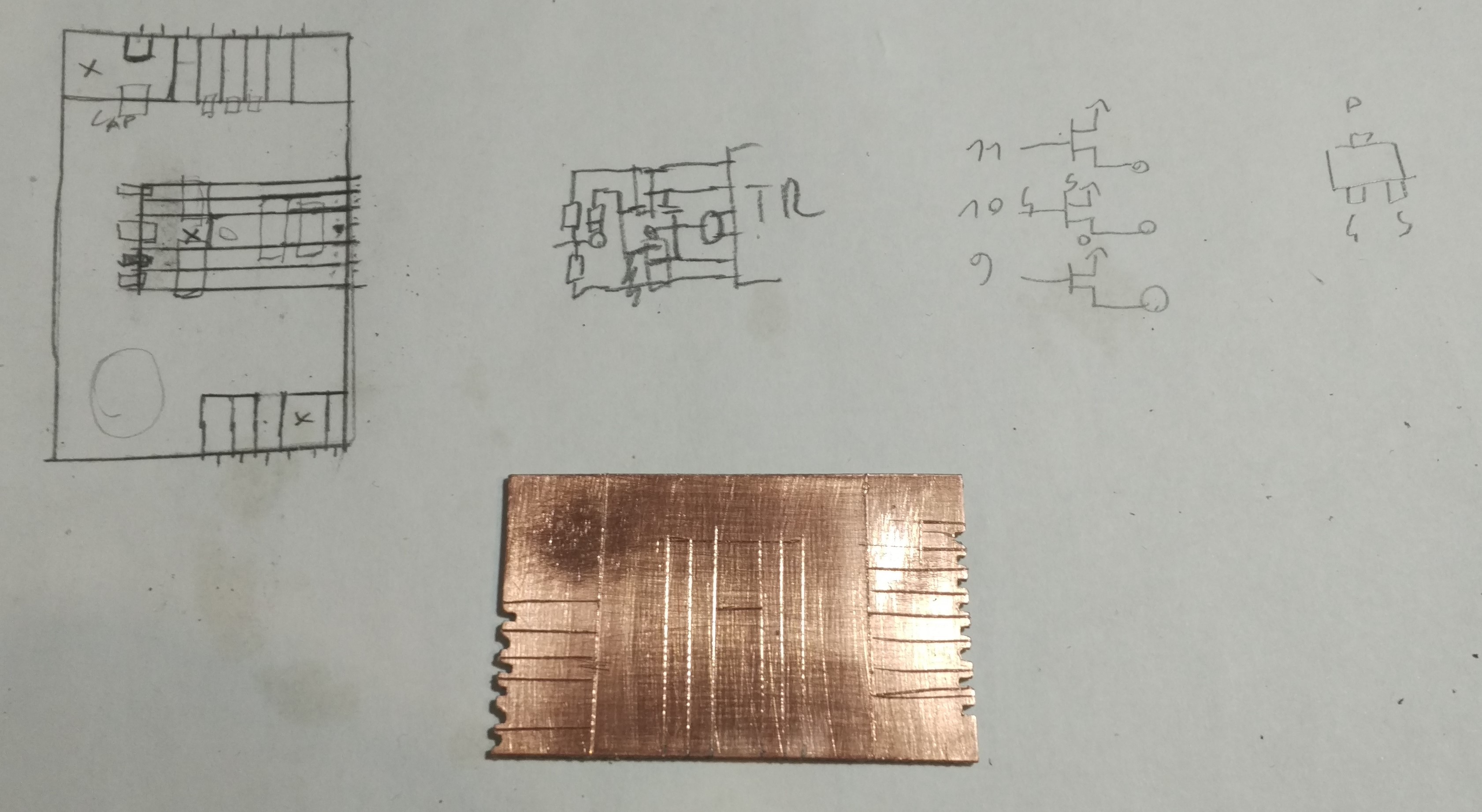
12/30/2018 at 16:53 • 0 commentsNow that all is working, it is time to assemble the thing into a whole. It will take the form of an Arduino shield. So I took a piece of PCB board, cut it to size, and used it as a foundation for my project. So basically, this is a circuit assembled on a sheet of FR4 with copper conductors, but it's just a part of it, so I hope it would still count as freeform.
Anyway, here's the pictures from the process. The shield connects to the upper part of the 'duino, since we don't need analog inputs and have enough digital GPIOs. I didn't want to drill holes for the pin headers, so I fitted the board between the headers and filed a little cut for them to fit better.
---------- more ----------![]()
![]()
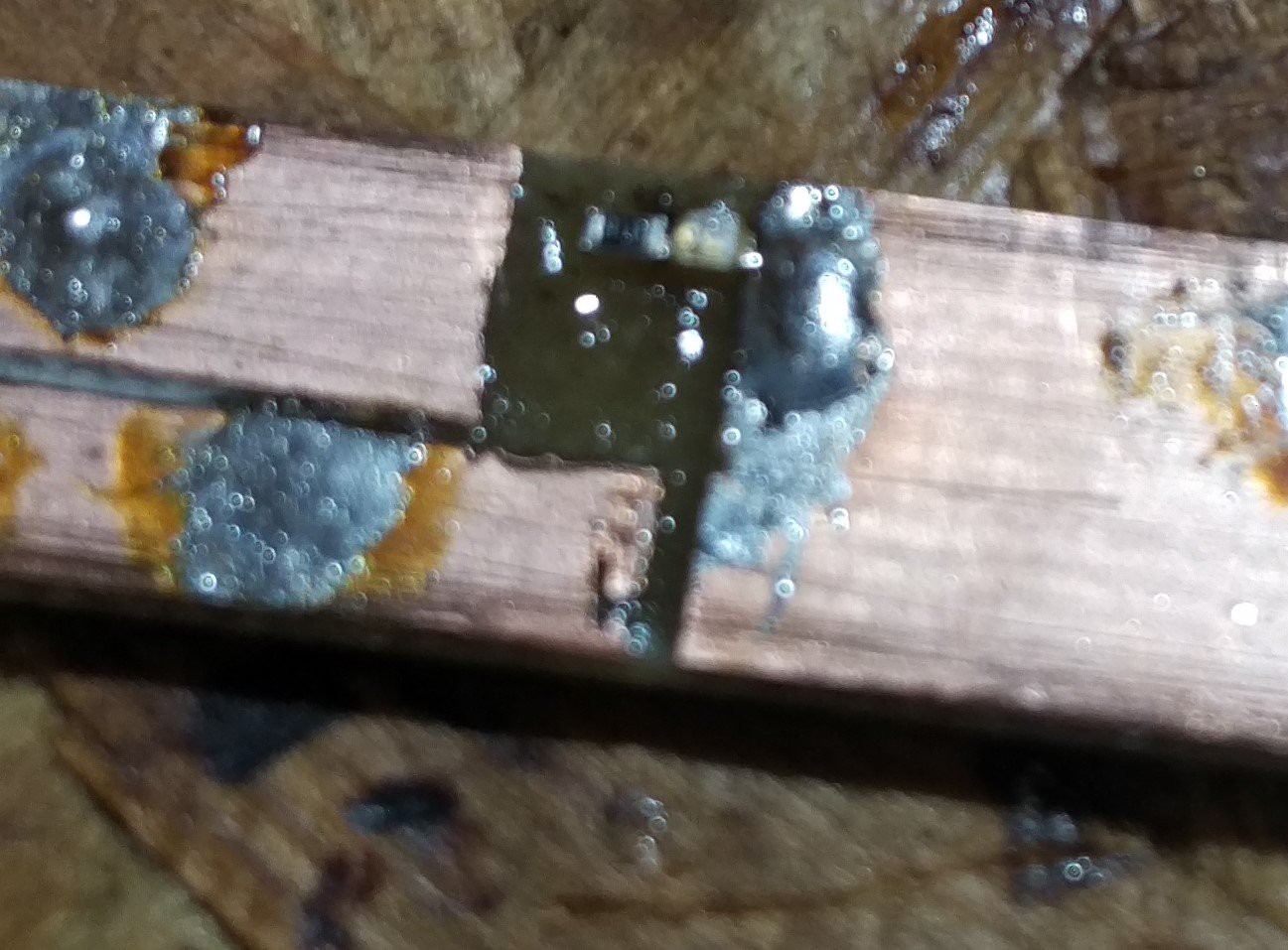
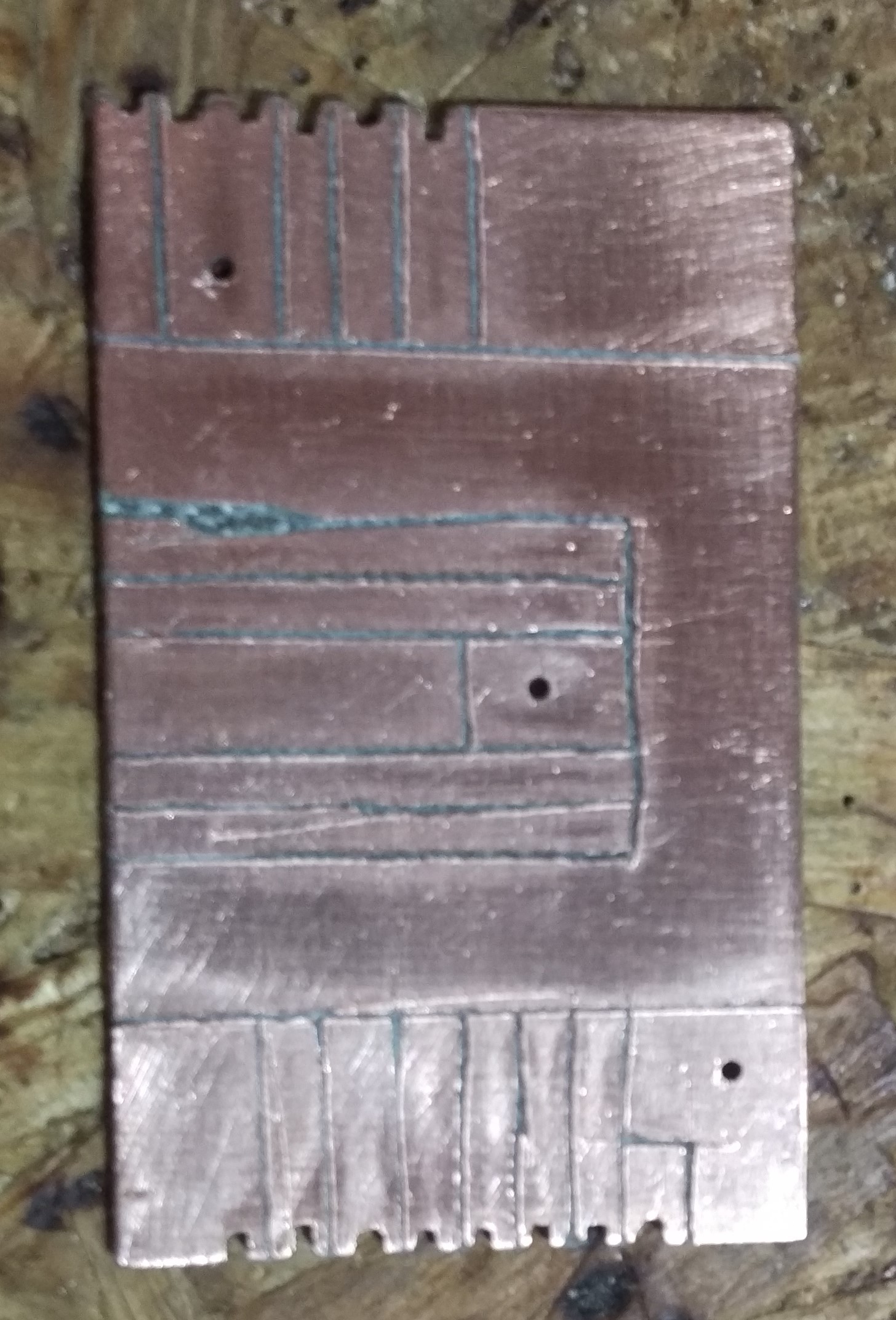
After planning the routes, I cut out the separations with a stationary knife, drilled and soldered some vias and bridges, and the board was ready to populate. It's not the prettiest thing I have to admit, but once the components are on, it'll look a little better.
![]()
![]()
![]()
![]()
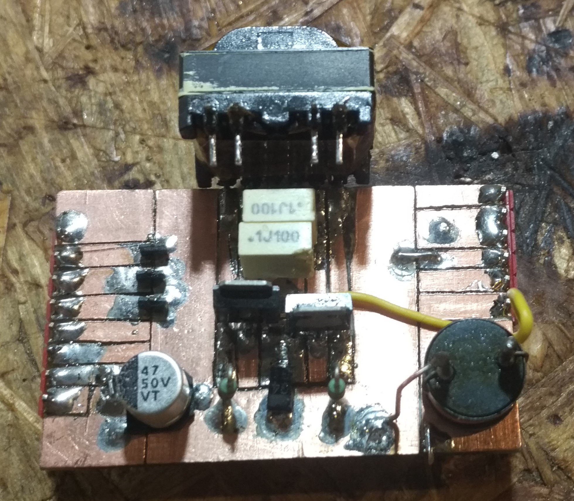
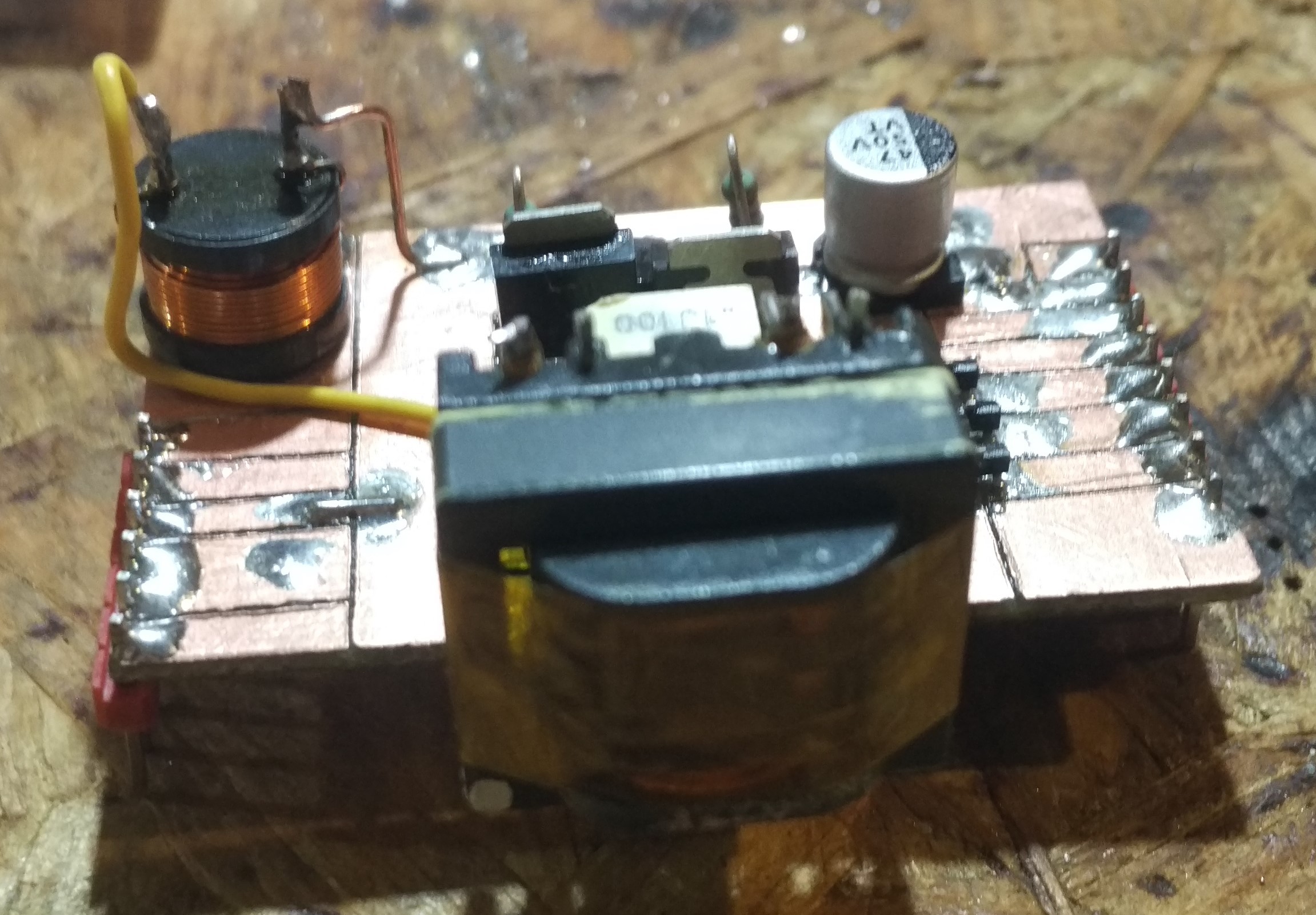
Then I soldered the components. I insulated the transformer with kapton tape, and soldered it at a 90 degree angle, so the HV side is upwards. This will hold the pillar to the tube. I also added a capacitor for extra buffer. The inductor wouldn't fit in the center, so I put it in the corner and used a wire to connect it to the transformer. I also added 3 P-channel MOSFETs to control the LEDs. These I removed later, as they were not needed, as it turned out.
![]()
![]()
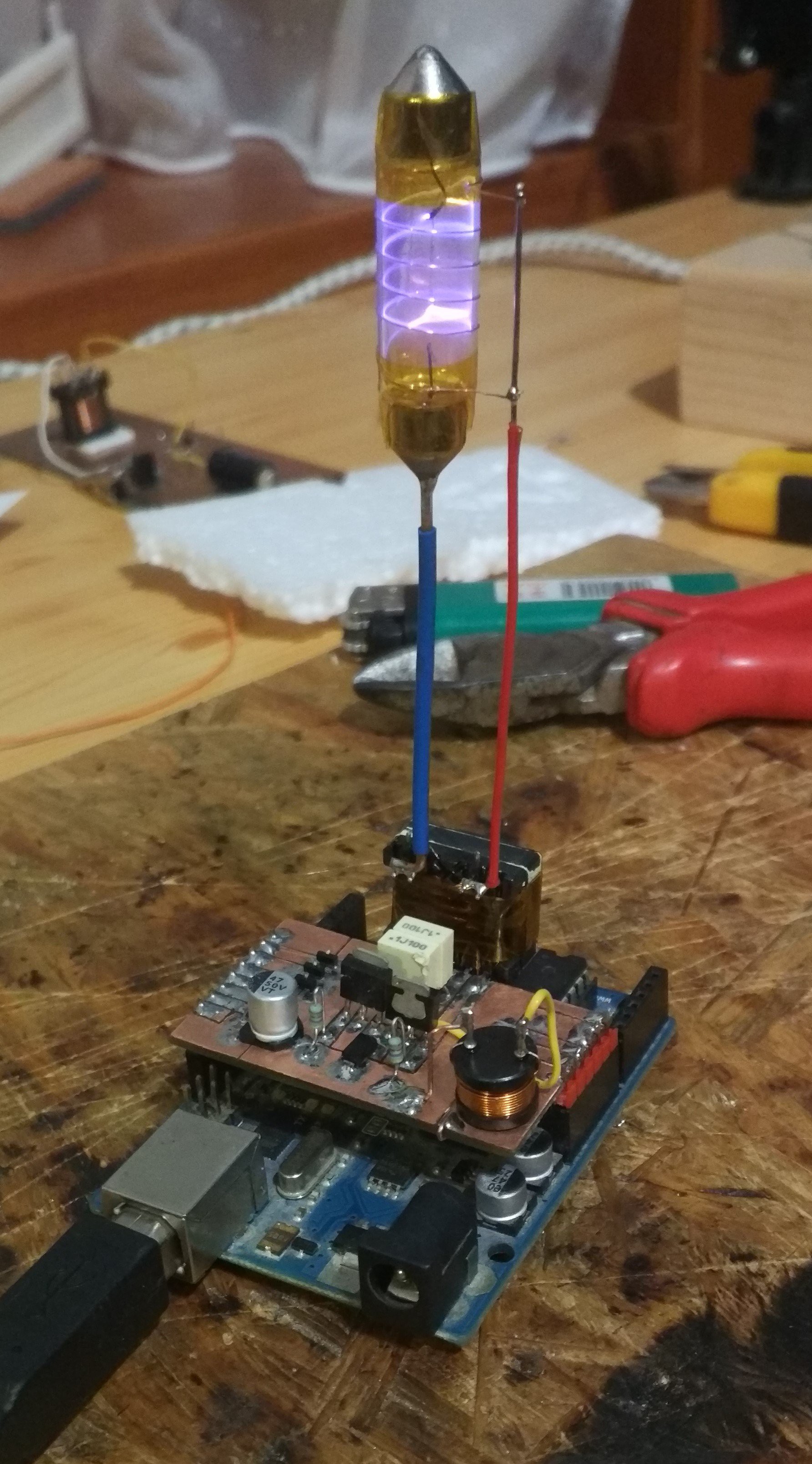
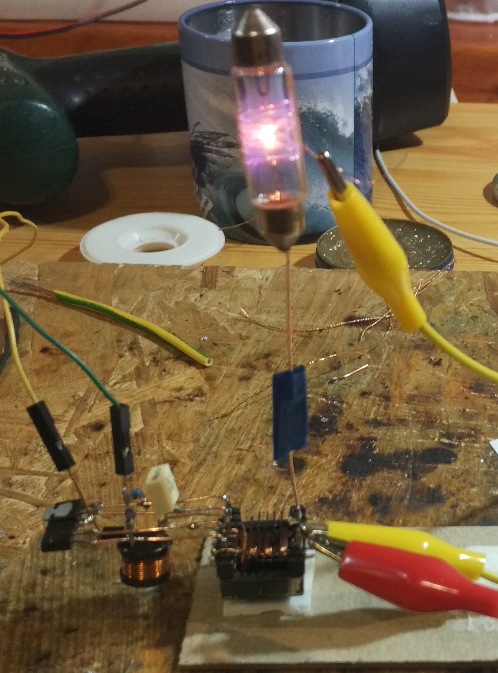
Using copper wires as pillars, I soldered the tube to the output of the transformer. Initially, I measured the current draw to be 870 mA, which is a bit much for the Arduino. By replacing the 1k pull-up resistors in the oscillator circuit to 4k7 ones, I managed to cut back the current to 470 mA. Good enough!
I plugged in the Arduino to USB, and it worked just fine. The result is... mesmerising.
![]()
-
Sparks of imagination
12/28/2018 at 22:05 • 0 commentsThe next problem was to utilize the voltage. Since it didn't produce any corona effect, I came up with the idea to build a plasma ball. For that, I needed a glass thing containing low pressure gas and a metal electrode. Luckily, light bulbs fit this description perfectly. A neon bulb would be ideal for gas discharge, but that's what neon bulbs do anyway, so it wouldn't be so spectacular. Instead, I tried to glow some filament light bulbs on fire. The filament alone didn't produce any plasma sparks, so an outer electrode was necessary to increase the electric field. And thus, these monster creatures were born:

Not only do they look disgustingly hideous, they do not work either. (Not so much of a loss.)
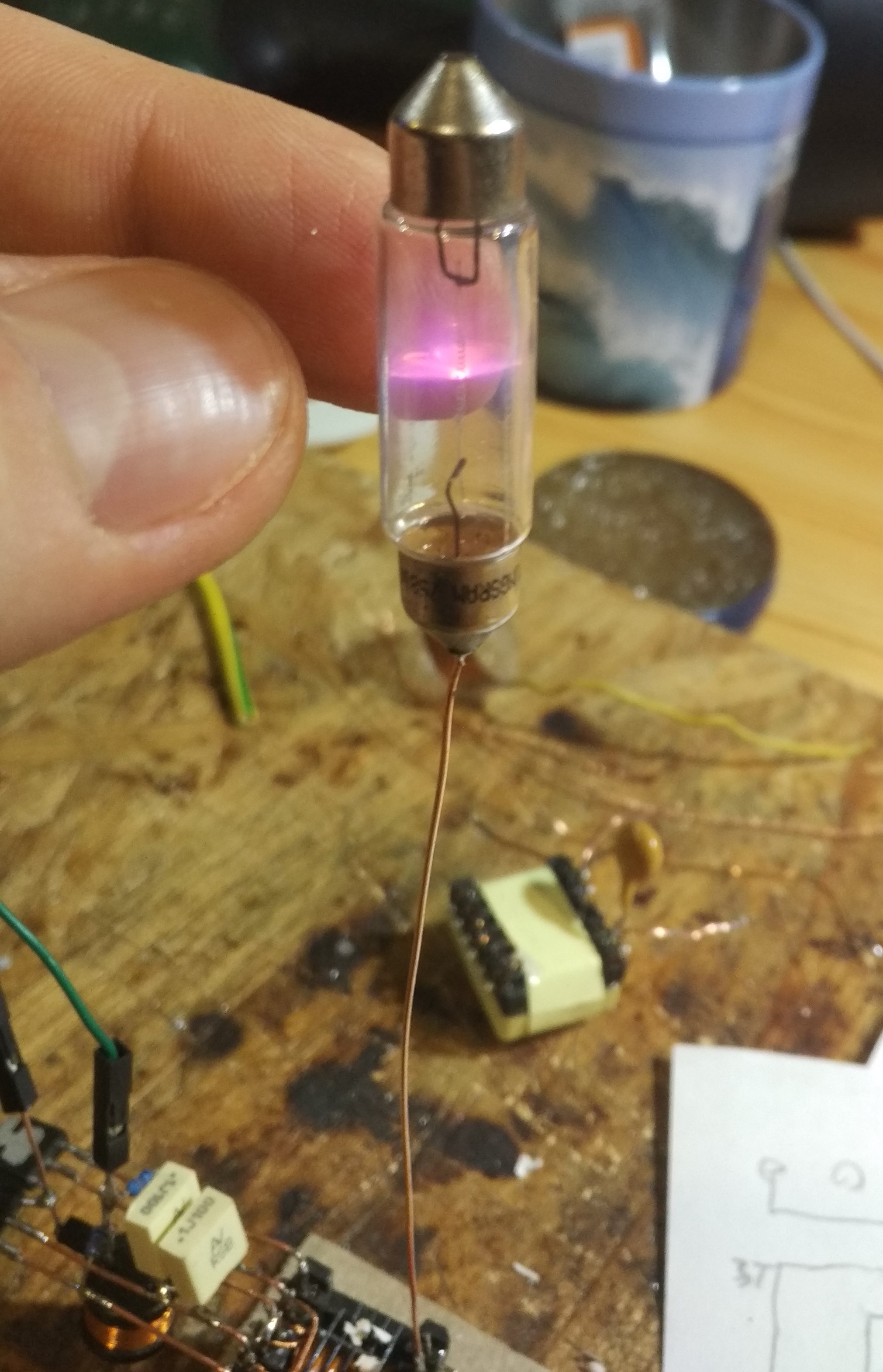
---------- more ----------Then I remembered these axial light bulbs I used to play with a lot. (They're from the interior light of an Ikarus bus.) I connected it to the output, touched the side of it, and beautiful sparks arose! Success! Now I needed a metal electrode instead of my finger. Given the straight, cylindrical form of the bulb, I figured I could coil some wire on it. And just like that, my plasma tube was born.
![]()
![]()
I was thinking a lot about how I could make this more aesthetic. At first, I couldn't figure out how I would be able to secure the wire to the glass. Then the obvious hit me: using some kapton tape, of course.


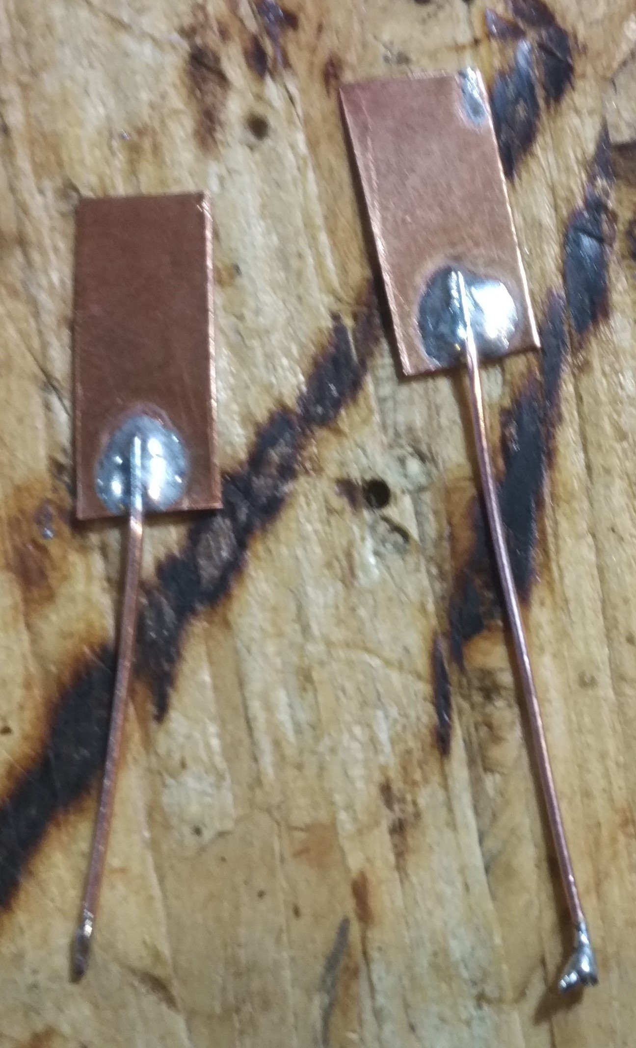
I also created a high voltage capacitor using insulator tape and bits of a copper sheet. It's purpose would be to limit the current. Later I would find out that this is not necessary. Anyway, it's a good idea to keep in mind in my future HV projects.
![]()
-
Getting high... voltage
12/28/2018 at 20:54 • 0 commentsMy main goal was to create some awesomeness, that is simple enough to implement in free form circuitry. A high voltage resonator seemed like a good choice. My first idea was to create something like a "tesla coil". I soon had to realize that these are not as simple as they seem to be, so I turned to using traditional transformers.
I had these little trafos lying around. They're from compact fluorescent lamps, which have an inverter inside their base to provide voltage to the tube. I also had some neon lamp bulbs, so the solution was obvious. Using a MOSFET and an Arduino, I managed to drive this with a 100 kHz square wave, and there was light. Funny thing is, since my square wave was asymmetric, only one electrode of the lamp was glowing.

It was nice, but I though I could do one better.
---------- more ----------Then I came across this video by GreatScott! where he creates an arc lighter using an inverter from and LCD monitor. This was just what I need! So I salvaged the transformer and the driver circuit from a faulty monitor PSU I had lying around (I have lots of junk lying around), rewound the primary coils, and so I began my journey in high voltage (well, medium voltage to be honest) electronics.


For the winding, I used this so-called "Litz-cable" that I saved from another transformer I torn down. These cables consist of many small diameter enameled copper wires. The purpose of using this instead of a single conductor is to minimize the losses from resistance due to the skin effect (especially in high frequency applications).
The driver is called a 'Royer converter'. I soldered together the circuit with the original components in-air, and supplied it with 5 volts. I could draw some neat arcs, and also managed to light a fluorescent lamp. Unfortunately, this still wasn't enough to show corona effect, so I needed something to put on top of it, but nevertheless, it is still a nice circuit.

The High-Voltage Spirit of Christmas
Freeform Arduino-controller Christmas Tree with the traditional ball of plasma top