-
Final touches
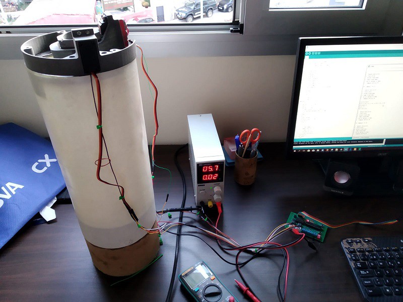
08/31/2019 at 11:12 • 0 commentsOnly some details are pendig in order to be able to launch next week. In the las few days,
- The rocket was painted
- The old servo cables were replaced with a more robust 4 wire cable.
- The old PCB connectors for the servos were replace twith more robust connectors.
- The switch cover that ensures that the parachute chord does not entangle with the switch was glued.
Still pending,
- Install arming connection for igniter
- Glue the bearing to the gimbal
- Thoroughly test the complete system
![]()
![]()
![]()
-
Inertia Measurement + Image Processing with MATLAB
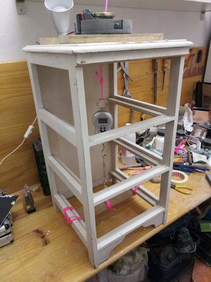
08/16/2019 at 19:28 • 0 commentsAt the moment, all the hardware is ready, only some software adjustments are necessary. One important remaining task is tuning the PID. For this purpose, I have to update the simulation parameters of the system with the latest values, and rerun the calibration process.
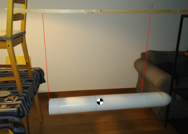
Today I set up a test bench in order to measure the rocket inertia, using the bifilar method, which basically consists on hanging the rocket with two chords, both at the same known distance of the center of gravity, and measure the period of the rotatory oscillation. You can find details at :https://conservancy.umn.edu/bitstream/handle/11299/182514/Habeck_UROP%20Final%20Report.pdf?sequence=3
You can see the set up below. In order to measure the period of the oscillation, after considering different alternatives, I choose to record the tip of the rocket with my mobile phone. I draw a black dot in a piece of masking tape and the video was processed afterwards with MATLAB in order to obtain the change of position over time. I can provide further details if anyone is interested. You can see the animation below also.
I tested to configurations, with a length of 1.15m and 0.80 m, both gave the exact same inertia with a negligible error. However, the dimensions for the computation and the position of the CoG have a certain degree of uncertainty due to the poor tools I used to measure them. Nevertheless, I consider the results to be accurate enough for my purpose. There is also a low frequency mode which I do not clearly identify but should not affect the measurements.
This method was proved to be very suitable, cheap, easy to set up, there are not any sensor cables affecting the measures (compared for example to using an accelerometer), and does not rely on human ability (compared to using a manual timer).![]()
![]()
-
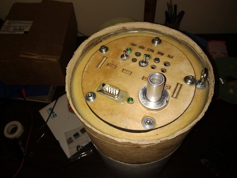
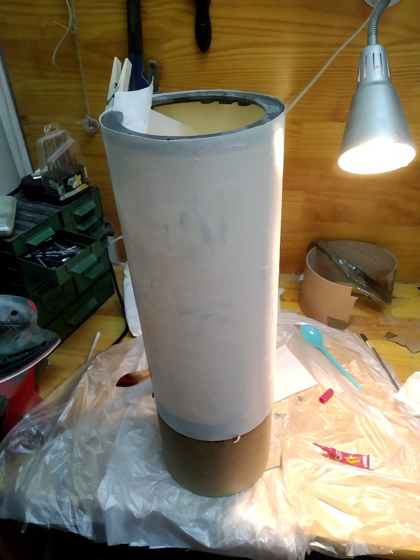
Electronics bay almost ready
08/07/2019 at 21:36 • 0 commentsThe electronics bay is almost ready. Still pending:
- Replace the cables powering the servos DC-DC with a thinner cable.
- Install the commercial altimeter for the parachute release.
Pending for the rest of the project:- Design and install the support for the rail guides.
- Install motor mounting tube in the gimbal.
- Glue the bearing to the gimbal
- Design and install parachute attachment to the upper section.
- Design and install some kind of protection for the electronic bay switches to avoid any problem with the parachute chord.
- Install cabling tubes from the electronics bay to the gimbal. - Paint the rocket.
- Measure the inertia of the complete rocket with the bifiliar technique.
- Compute the aerodynamic coefficients.
- Introduce them in the MATLAB and calibrate the controller.
Finally, I have date for the launch, 7/8 September 2019, in the Spain Rocketry Meeting.
![]()
![]()
-
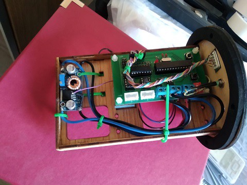
Working again on the project!
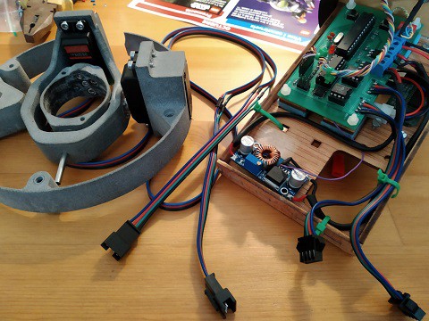
07/13/2019 at 18:21 • 0 commentsAfter a long break caused by may personal reasons, I have continued with the project.
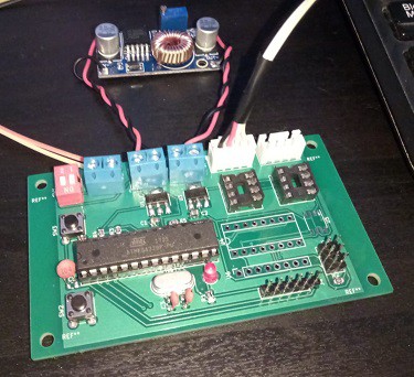
I assembled some parts of the motor section of the structure. The fixed support for the vector sytem was glued with epoxy, as well as the coupler for the separation. This required two iterations because of the misalignment of the cylinders. I have also wired the two servos to the PCB and tested to work as expected.
![]()
![]()
![]()
-
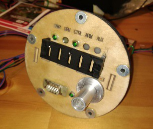
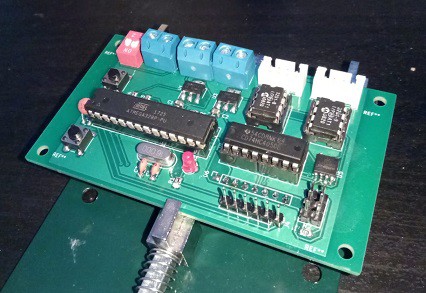
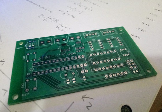
PCB is working!
01/13/2019 at 18:10 • 0 commentsAll components tested now including, ADC, MPU9250 gyros and accelerometer, voltage regulators, servo control, buttons and flash memory. I finally soldered the flash memory in the incorrect footprint by bending the legs, it took some time but it works.
Now, it's coding time!
![]()
-
Testing the PCB...
01/09/2019 at 22:56 • 6 commentsThe board is working, voltages regulators work, led is ok, .. but unfortunately the footprint of the SPI Flash was incorrect ... I have to decide if I re-do the PCB or make some kind of workaround :(
![]()
-
PCB Received!
01/07/2019 at 20:25 • 0 commentsI have just received the first iteration (and I hope the last one) of the control board for the rocket. Ordered at https://www.seeedstudio.io/.
![]()
-
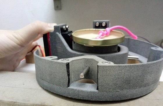
Gimbal static load test
01/05/2019 at 21:22 • 0 commentsAs I commented with @Mike Szczys , today I performed the static tests in order to ensure the structural integrity of the gimbal. The test was a success with some observations to be considered.
- The test bench was quite improvised and low cost but worked nicely for the purpose of the test.
- The test reached 12.2 kg without any strange noise.
- The servos worked smoothly after the test.
- The plastic structure recovered totally the initial shape and there is no sign of permanent deformation.
- The inner rings had no visible deformation.
- However, the external structure deformed significantly, but the supporting is no representative of the real conditions. I will perform finite element simulation in order to study the deformation of the body tube and make sure that deformations are reasonable and there is no risk of local buckling. Local reinforcements will be introduced to the zone if shown to be necessary.
- Also, the bearing of the outer ring slightly moved out of the hole. I will glue it with epoxi to make sure it stays where it should. Maybe this can be avoided with some geometry changes if I ever re-design the gimbal.
![]()
![]()
-
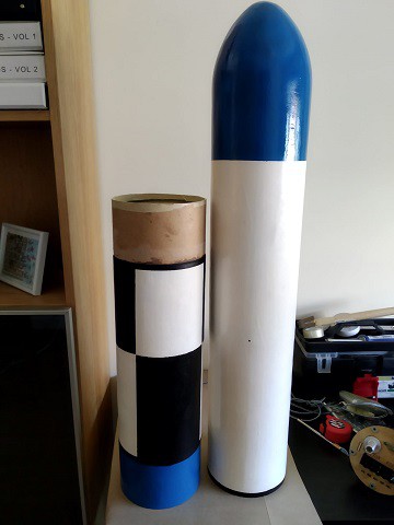
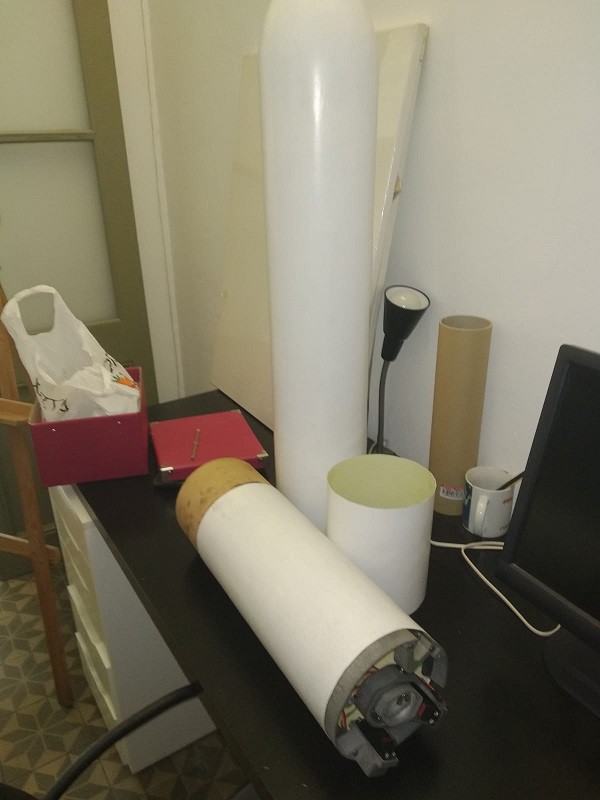
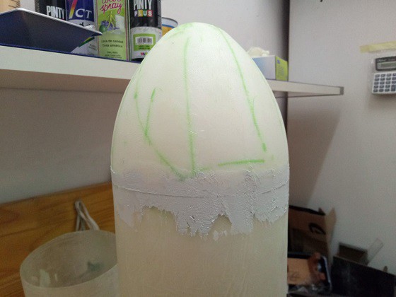
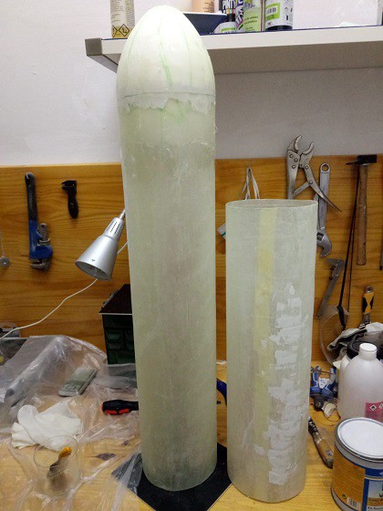
Working on body tubes and ogive
01/02/2019 at 23:32 • 0 comments![]()
![]()
-
Motor gimbal motion test
01/02/2019 at 11:37 • 0 commentsHere you can find the motion test for the assembled gimbal with the servos :D