 Dennis
-
1UBIRS assembly
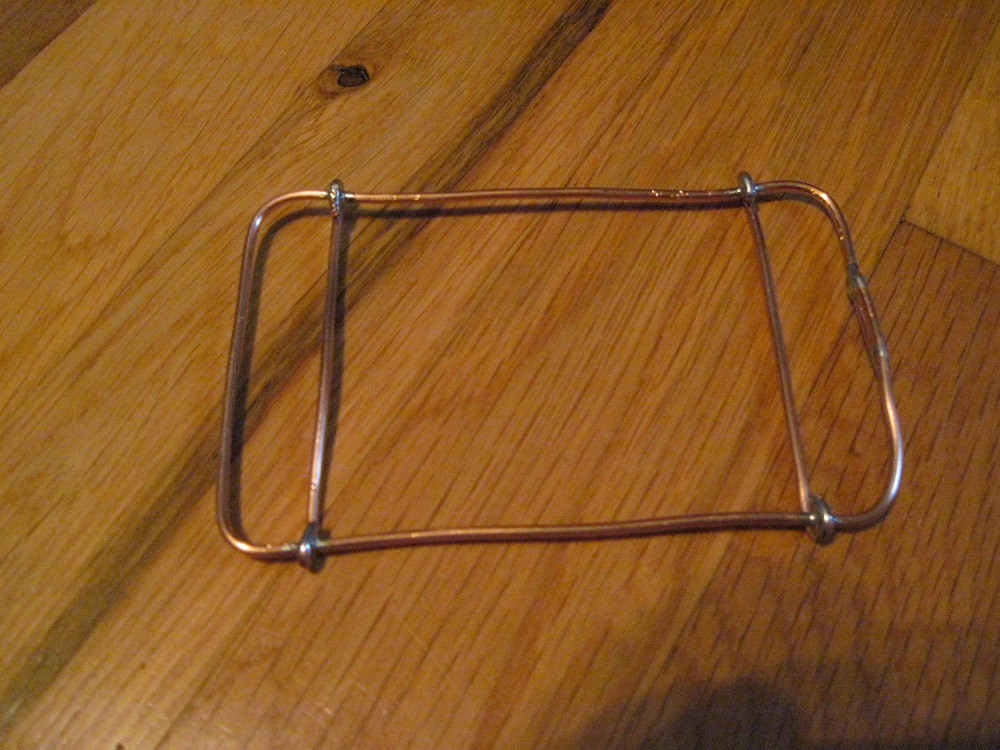
UBIRS started with a 14 AWG frame which also serves as the common bus.
![]()
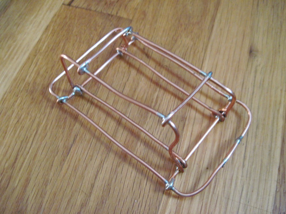
Next six more 14 AWG wires are soldered to the frame to serve as the PIC16F873A mount.
![]()
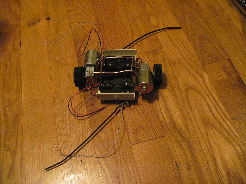
Two plastic angles are added and photo resisters, battery holders and bump switches with two cable ties carefully bolted to them. The two motors are also pressed and tie wrapped into place.
![]()
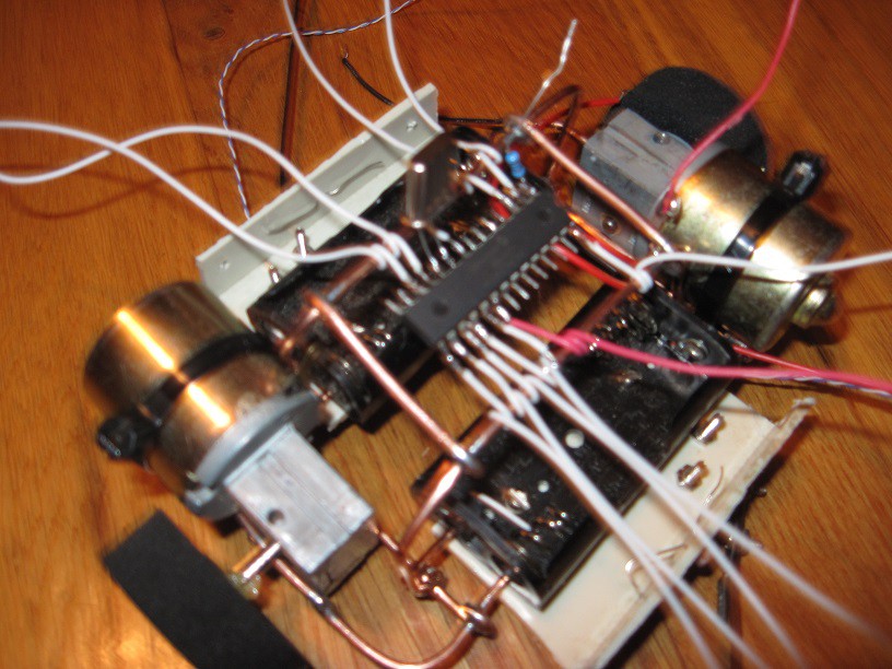
Add the PIC16F873A and solder wires to the PIC16F873A.
![]()
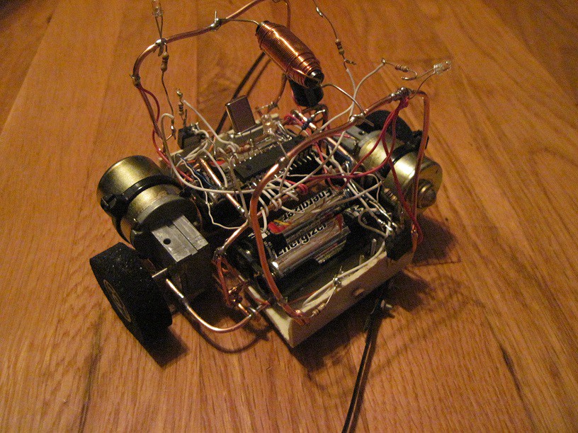
Last install the positive 14AWG bus and the motor positive bus and solder the wires from the PIC16F873A to the photo resisters, bump switches, motors and the LEDS.
Install an inductor between the two positive buses and add a filter capacitor between the motor positive bus and common bus.
![]()
UBIRS
Ugly Bacteria Inspired Robot Sculpture. Search's for light while avoiding objects.
Discussions
Become a Hackaday.io Member
Create an account to leave a comment. Already have an account? Log In.