Darren V Levine
-
Software for Simulation and Hardware Control
02/22/2020 at 01:27 • 0 commentsSoftware is here!
I've updated my github with all the details:
https://github.com/DarrenLevine/TipTapA single python library tiptap.py is provided to interface to both Simulation and Hardware.
Its provides identical function calls on either target, so that you can develop your control algorithms in simulation, and then run the identical script on hardware without any extra work to port your code from simulation to hardware.
To get started, run, and read:
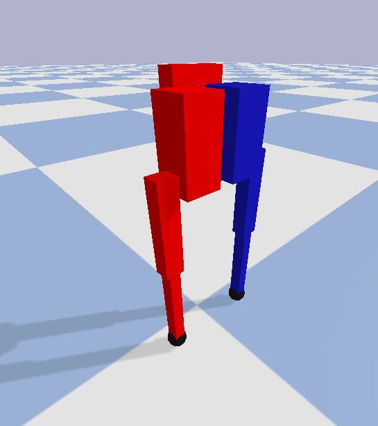
https://github.com/DarrenLevine/TipTap/blob/master/software/example_OperatingTipTap.pyIf you aren't running on the TipTap hardware, it will automatically detect that, and start a simple pybullet simulation:
![]()
Feel free to try making the robot walk!
if you don't have access to hardware, but want to see if it'll work on the actual TipTap robot, just contact me and I'll run it on mine, and send you a video of the results.
Best Regards,
Darren
-
Robot STL and Design Files Published
11/23/2019 at 22:04 • 0 commentsHi All,
I've published all the instructions and files to make a full TipTap robot here:
https://github.com/DarrenLevine/TipTap
In the next week or so I'll be cleaning up my interface software and providing that as well, so anyone who wants to try and make it walk around can do so.
Have a great day and thanks for looking!
-Darren
-
Publishing Actuator Design Files
11/22/2019 at 18:37 • 0 commentsHi All,
I've published all the instructions and files to make one of the complete open source TipTap motors here:
https://github.com/DarrenLevine/TipTapMotor
Stay tuned for the rest of the robot files coming soon.
-Darren
-
Writing Code
10/06/2019 at 20:00 • 0 commentsHi Everyone,
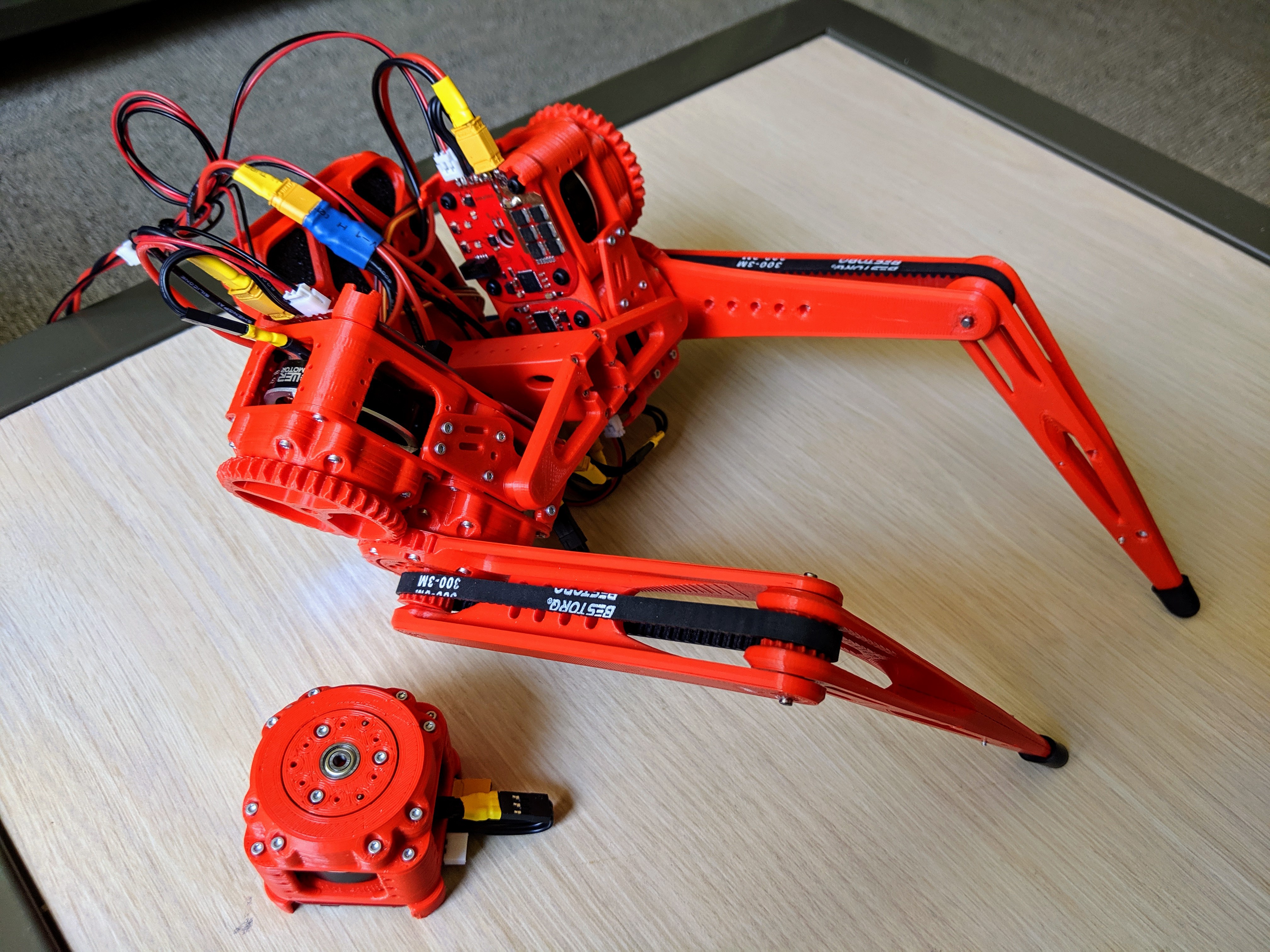
This is what the robot looks like now!
![]()
In the last couple months I had to redesign TipTap's beaglebone blue backpack, due to the integrated RS485 to uart converter chips continuously burning out, and in general being unreliable. I tried several other converter chips but had trouble finding another reliable and cheap option. In the end I had to move to a larger form factor by integrating a "JBtek USB to RS485 Converter Adapter ch340T" (the large black usb stick now on the back of the robot), which works very reliably, and as an additional plus lets me plug in the converter to any computer to test the motors very easily since it's just a usb stick.
After that resign, I ran into software and networking difficulties using the beaglebone's integrated solutions. Eventually I moved to a setup where I SSH into the board via VSCode over wifi, which works like a charm and has really sped up my software development workflow.
The power mangament also let to some difficulties, the servo rail is only connected to the lipo battery input terminal on the beaglebone, so I needed to "fake" a lipo input instead of being able to use the standard power connector on the beaglebone. To do this I take the 24v power supply and pass it through a buck converter down to 8v which powers the servo rail and beaglebone, unfortunately, the lipo terminal has a battery management circuit integrated into it which will interpret the slow ramp-on of the buck converter as a bad battery and prevent further current draw (preventing the beaglebone from turning on). As a workaround I'm plugging the power in, waiting for the buck converter to stabilize, and then plugging in the buck converter into the beaglebone. I'll do this until I can come up with a compact power-on-delay circuit that does this automatically (as long as it doesn't impact my < $500 robot goal).
Most recently I've been dealing with a latency issue with reading the IMU's DMP fused quaternion data. So, for the moment I've resorted to using just the accelerometer data, which has negligible latency. Which finally let me test out some simple control routines while tethered.
The code that created the behavior in the above video isn't very complicated, it's just a PID loop position to torque controller tuned to make the legs really springy and compliant. I'm using weighted averaging as a low pass filter on the accelerometer data, and fed all that data in as simple heristic proportional gains, all manually tuned at the moment (I'm just using this to test the hardware / compute performance, later on I'll move to more advanced control schemes). Here's the python script:
from tiptap import * CustomCal = [-223.67956054016938, -493.2387273975738, 93.62142366674297, 778.4646372167543] Controller = PIDloop(InCalibration=CustomCal,TorqueLimit=0.4) avg_zaccel = 0. avg_xaccel = 0. avgz_ratio = 0.4 avgz_inv_ratio = 1 - avgz_ratio avgx_ratio = 0.8 avgx_inv_ratio = 1 - avgx_ratio while True: accl = mpu9250.read_accel_data() avg_zaccel = avg_zaccel*avgz_ratio + accl[2]*avgz_inv_ratio avg_xaccel = avg_xaccel*avgx_ratio + accl[0]*avgx_inv_ratio Roll = -avg_xaccel*7 Rtheta1,Rtheta2,Ltheta1,Ltheta2 = gla.GetLegAngles(-avg_zaccel*0.15 + 3*np.pi/180 + np.pi/2, np.mod(int(time.time()/0.3),2)*2-1) RightLegServoDeg(-2 + (Roll>0)*Roll) LeftLegServoDeg(-2 - (Roll<0)*Roll) Controller.Apply([Rtheta1*180/np.pi, (-Rtheta1-Rtheta2)*180/np.pi, -Ltheta1*180/np.pi, (Ltheta1+Ltheta2)*180/np.pi]) ExitProgram() # shuts down motors and cleans up signal handlers -
Finalizing the Motor Driver and Hardware
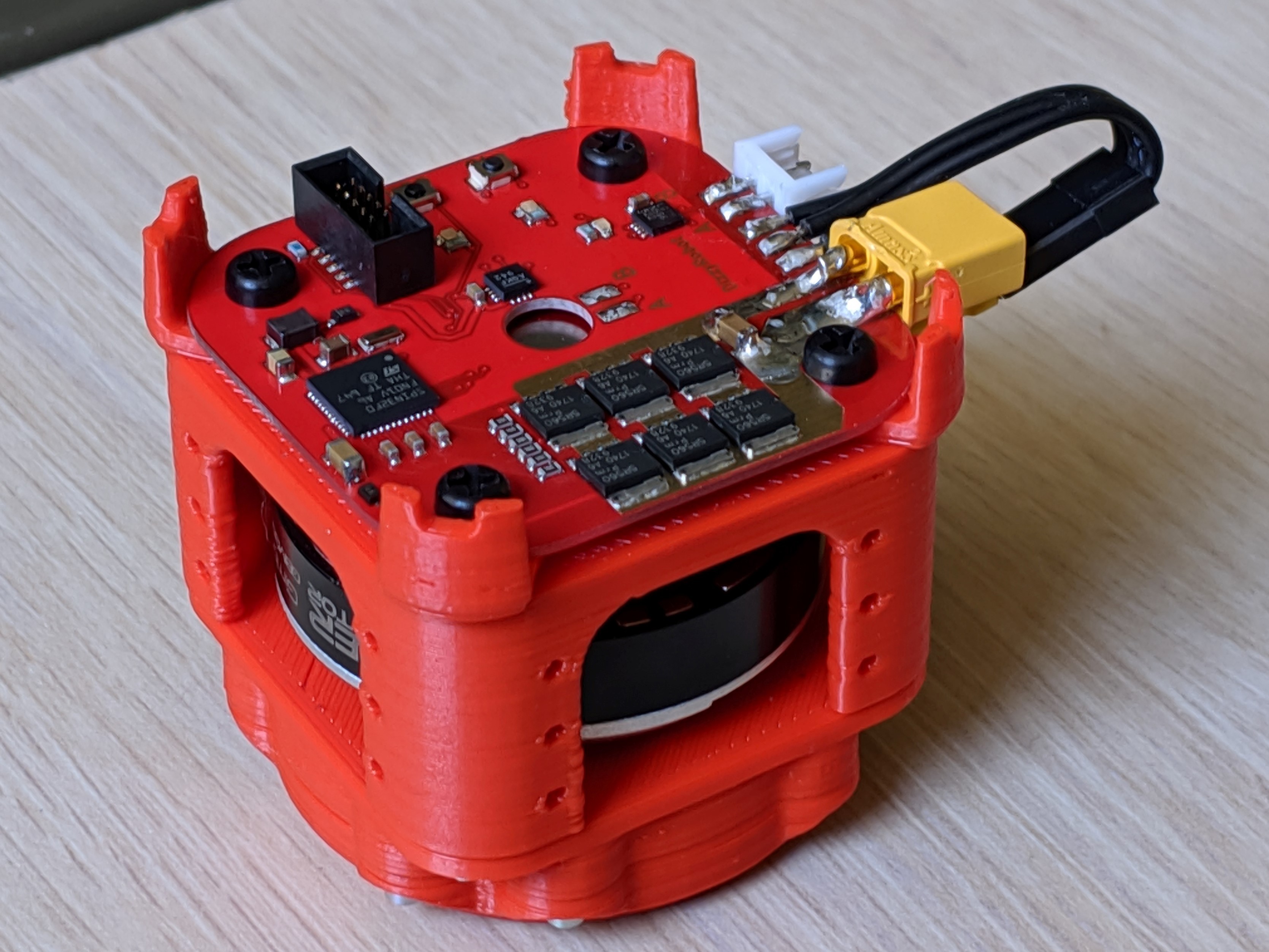
08/18/2019 at 22:35 • 0 commentsBefore I get started, I wanted to give a shout out to Misha at dizzy.ai, most of the progress in this post is due to finally narrowing down to a torque controller that fit this application's needs. Specifically, I used four of his absolutely fantastic DirectServo designs. I tried a few different ESCs that could do torque control, however most were either too expensive, or too large to reasonably integrate into TipTap. ODriive was my favorite as far as software goes, and I learned a lot from playing with their firmware, but in the end it was too expensive and large for this application. The DirectServo ended up being the perfect combination of easy to use and high performance that I needed for this application.
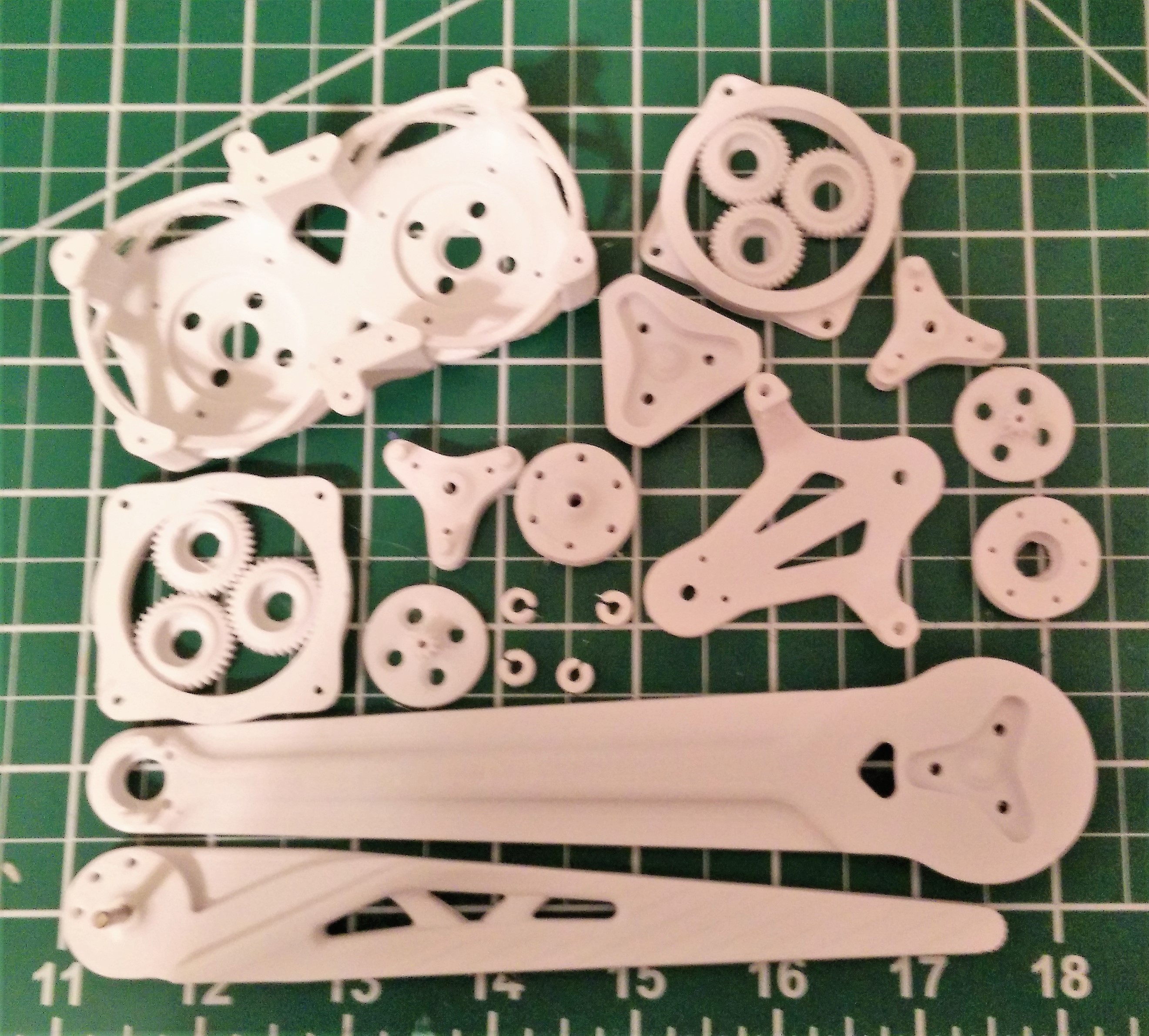
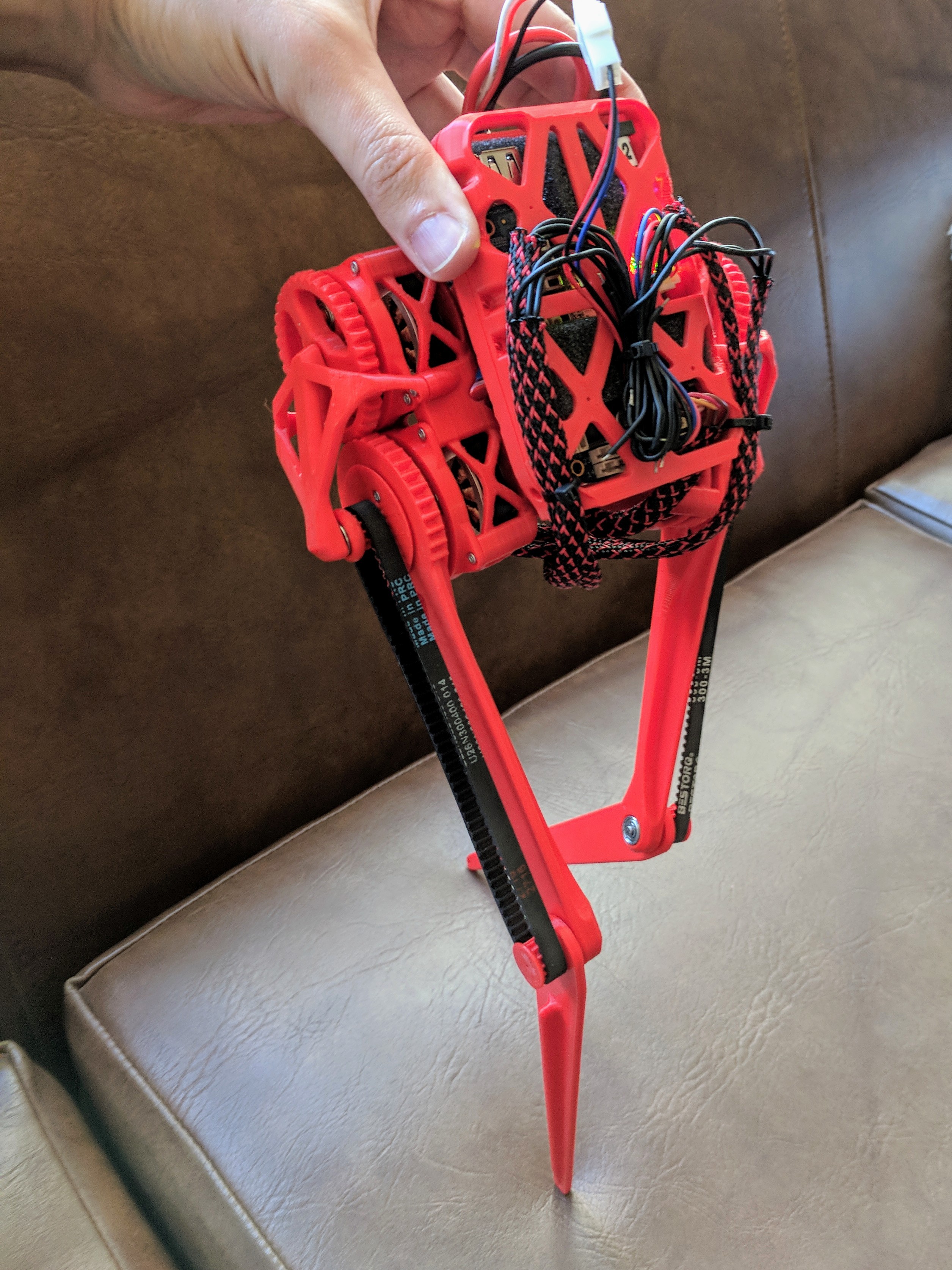
Once I decided to go with the DirectServo , I redesigned both the gearbox and motor enclosure to make it modular and to solve some persistent mechanical issues. Mainly that the load path through the gearbox could only withstand loads that didn't apply off-axis torques (leading to exploding gearboxes :( ), and that getting smooth predictable movement with the imprecise 3d printing of gear teeth was a continuous challenge. Moving to a Herringbone gear pattern solved the printing smoothness/yield problem, it turns out the pattern is much more forgiving with printing defects than the typical spur gear pattern. For the load path issue, I finally broke down and added 6705 Thin Section Ball Bearings (25x32x4) under the hood of each gearbox to redirect the load. The bearings are more expensive than I'd like at $15, but the final gearbox is incredibly robust as a result. Another benefit of adding the bearing was that I no longer needed an extra supporting enclosure on the outside of the gearbox. Here is a picture of the cross section of the new design:
The final cost for one of these 3d printed torque controlled gimbal motors is about $74 . That's $15 for the bearing + $38 for the DirectServo + $18 for the gimbal motor + $1 for the encoder magnet + ~$2 in fasteners and filament.
The dimensions are 47mm x 47mm x 47mm.
![]()
![]()
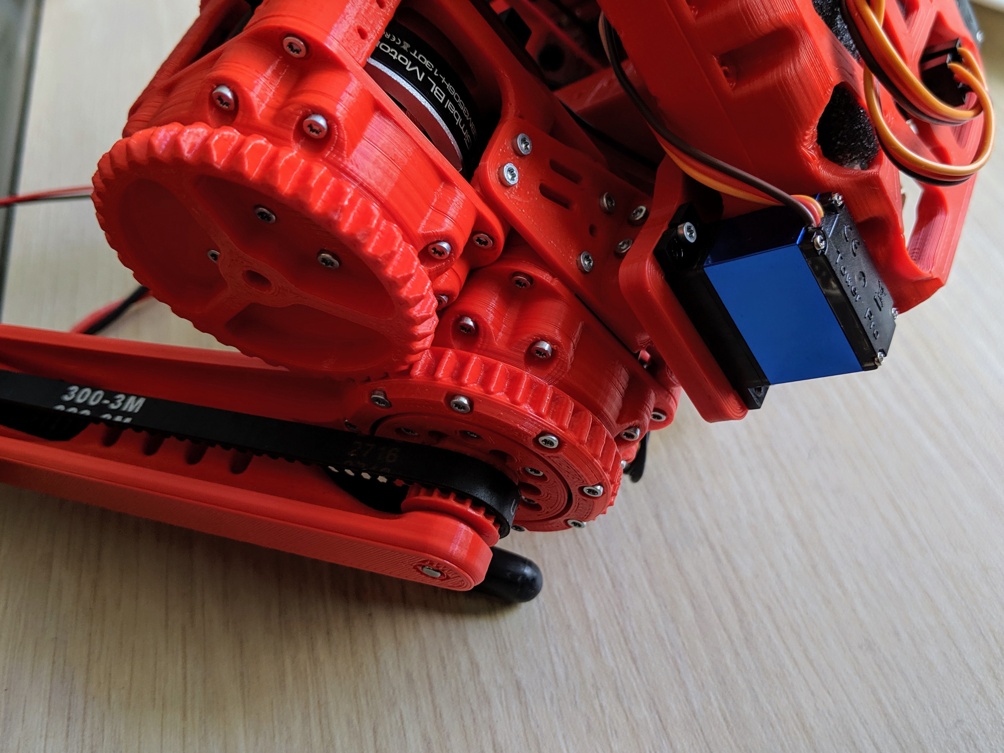
I also redesigned the legs, so that they were supported on both sides of the pulley all the way to the feet, which got rid of the last bit of backlash/flexure I was experiencing.
For the torso, the previous design had a large moment arm on the servos which created too large of a torque for the servos, and so in an effort to make the hip's side-to-side pivot point closer to the front-back rotation point (reducing the forces on the hip), I redesigned that as well.
First by trying a double pivoting linkage design, as seen here:
![]()
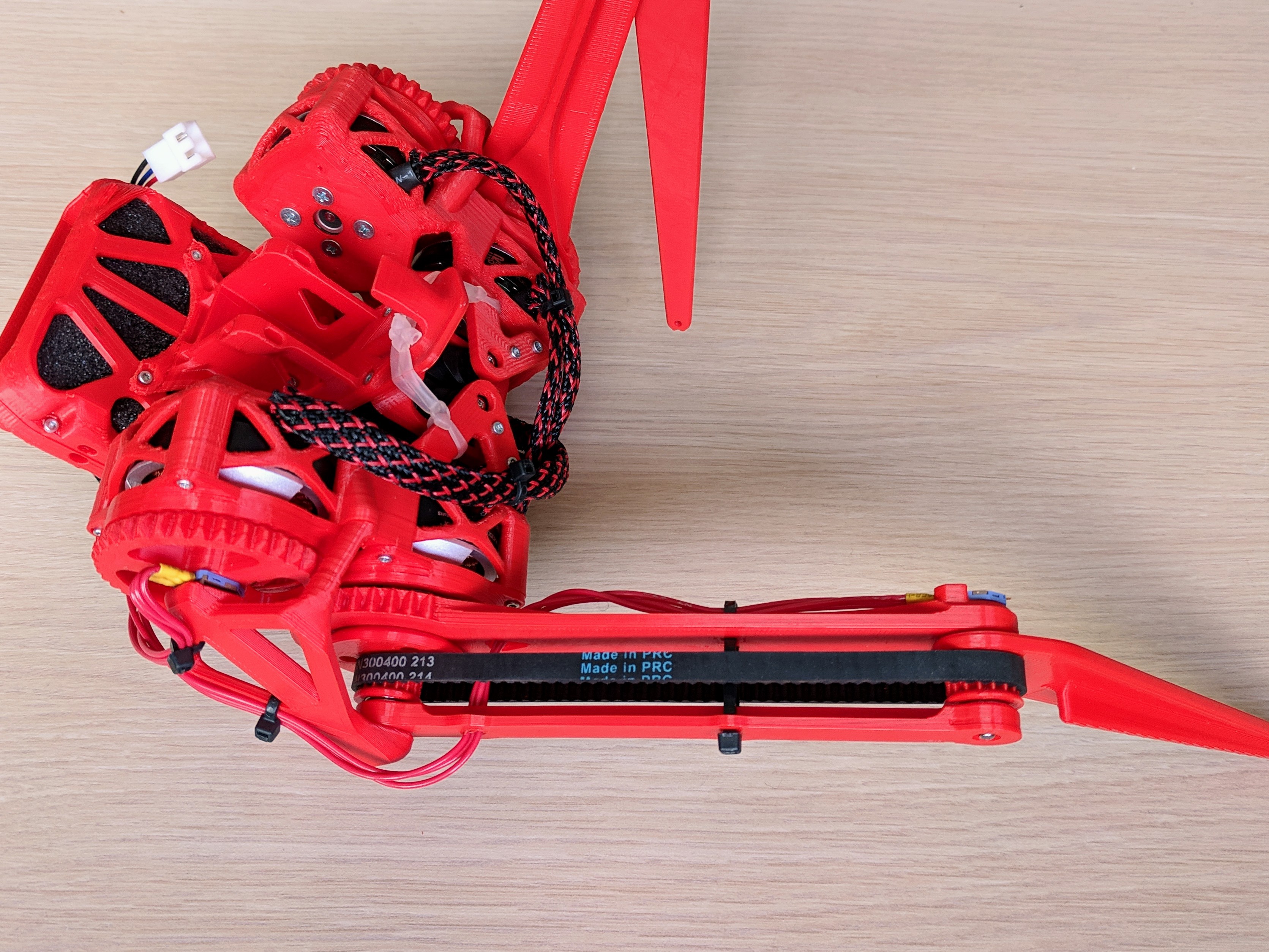
However, as you can see, that resulted in a lot of backlash and therefore vibration. The linkages also added complexity, and because the servos were located between the legs, it forced the legs to move apart, which is not ideal for a walking gate. So I removed them in favor of a more rigid direct servo mount design on the back of the robot:
![]()
As well as reinforced the centerpiece and beaglebone mounting plate, essentially combining them and making the center more tube-like to reduce the torsional flexure I was seeing. You can see the final design here:
![]()
All in all, I've very happy with how rigid and durable everything turned out, and especially with how quickly the legs can move as well as their torque when given 24 volts.
My work going forward will be in setting up a testing apparatus and working on software to make it walk/jump/move. Eventually I would also like to print some clear and thin plastic protective shells to cover the moving parts and protect against falls.
That's it for now. Thanks for looking!
-
Initial Work and Reducing lashing in leg/hip
02/09/2019 at 23:59 • 0 commentsInitial Work:
Log update: 01/05/2019
As a first step I built a Port-Hamiltonian simulation framework in MATLAB, in order to teach myself the low-level math/physics. It turned out to be extremely slow, and so I could only use it for 2D sims. Here is my first attempt at a low-cost heuristic based stabilization controller (very Monty-Python-esc I know).
![]()
More recently I've moved to an articulated body Featherstone simulation framework in MATLAB. Here is another even simpler heuristic based control scheme:
![]()
Eventually I'll work on efficiency and stability, but for now this does have the advantage of being naively extensible to arbitrary N-Jointed x N-Limbs without a training period. My next steps are to progress more on the hardware end in order to test any controllers on actual hardware.
On the hardware end, I made many many early mistakes, including under-sizing motors and components. I created a small 3d-Printable 9:1 planetary gearbox that overlays each motor which fixed that issue:
![]()
Here is a video of an early prototype leg:
![]()
The cable design turned out to be very difficult to work with and produced unnecessary strain on the motor housing, so I moved to a belt/gear design even though it adds weight. The 9:1 planetary 3d-printed gears also needed a redesign to produce better printer yields. The next iteration included more robust components, though it was far from a final design. Producing such small parts in order to try and conserve weight and size means I'm always finding new bottlenecks that need to be fixed.
![]()
Reducing lashing in leg/hip:
Log update: 02/09/2019
I updated the leg design with slightly thicker limbs and added a supportive bar on the external femur. The extra bar allows the belt to be tightened down significantly more, reducing play to a much more acceptable level. Here's a picture of the new leg all assembled and instrumented:
![]()
Other progress:
I'm did some more work to improve yield issues with the very small planetary gears on each motor (the teeth are the width of my printer's nozzle), in particular upgrading my 3D printer's firmware last weekend helped a bit. Although it is time consuming, a few more iterative tweaks are probably in order. Not having to resort to metal gears will be a huge cost/time saver in the final product.
I'm using 333 degree potentiometers on each joint instead of encoders to significantly reduce cost and size. They produce a single analog signal that needs ADC sampling and kalman filtering (due to reduced performance in vibration). At the moment, I'm doing that in software on the beaglebone (located on the back of the robot), which works decently well. So, I'm hopeful this cut-corner will work out. However, I'll now need to either convert that signal to one compatible with the Odrive's discrete encoder inputs, or modify the Odrive's firmware to do the job. Still more tinkering to do on that front.
As for the idea of building my own motor controller, after looking at the various resources and designs available such as Ben Katz's: http://dspace.mit.edu/handle/1721.1/118671#files-area, I'm both more excited about making a custom board, and more aware of how large of an endeavor it would be ( VESC (Best Open Source ESC) || DIY or Buy). So, I'll likely do it as a separate project once I'm happy with TipTap's base model platform.
That's it for now. Thanks for looking!
TipTap
A 3d-printed bipedal robot. A desktop option for semi-direct drive walking research.