I glued the base plate together from scraps and then brought it into a circular shape with the router.
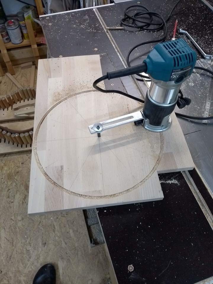
At the edge I drilled two rows of holes into which the LEDs for the seconds display are inserted later.
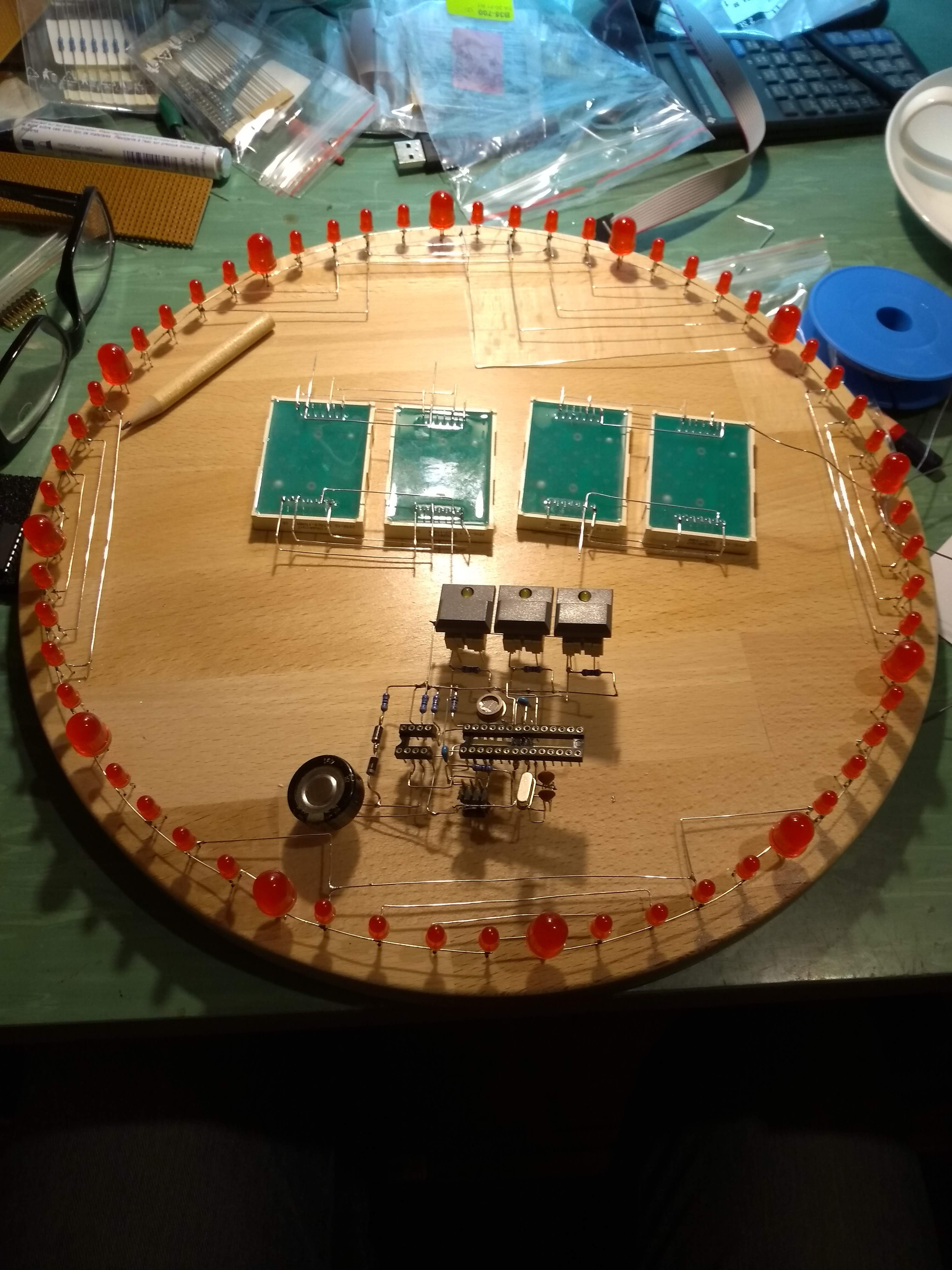
When wiring I try to use only right angles for optical reasons. The circuit is wired with 0.6mm silver plated copper wire.
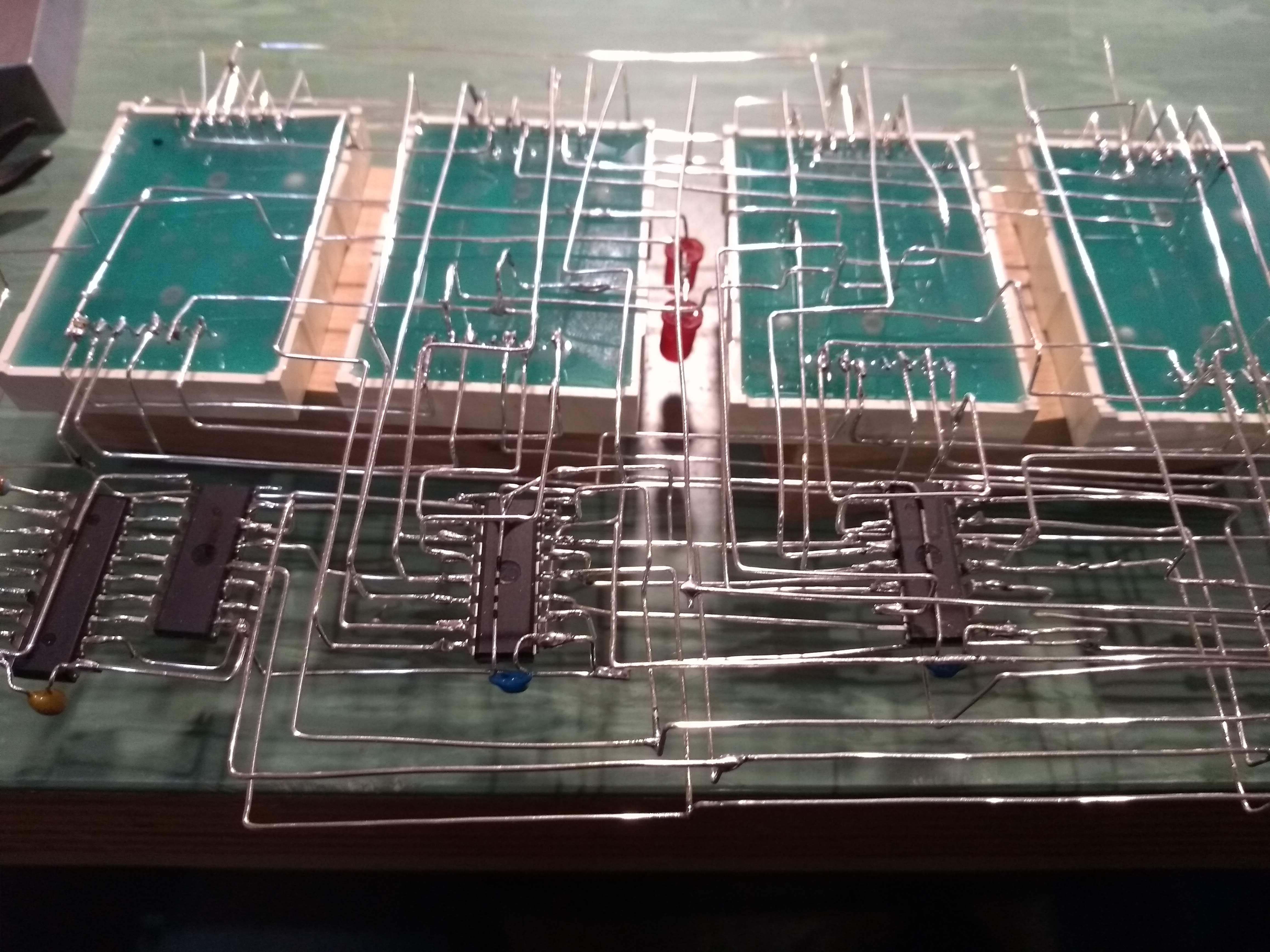
The wiring is a real challenge ... as you can guess on the following picture. I built three main components separately : CPU, display with shift registers and LED ring.
Before the display wiring will be mounted on the board, I double checked the wiring again and found some bugs.
The mechanical construction is nearly done. There are still missing connections in the LED ring and the connections between the 3 components. But after building up the display I'm not worried about it.
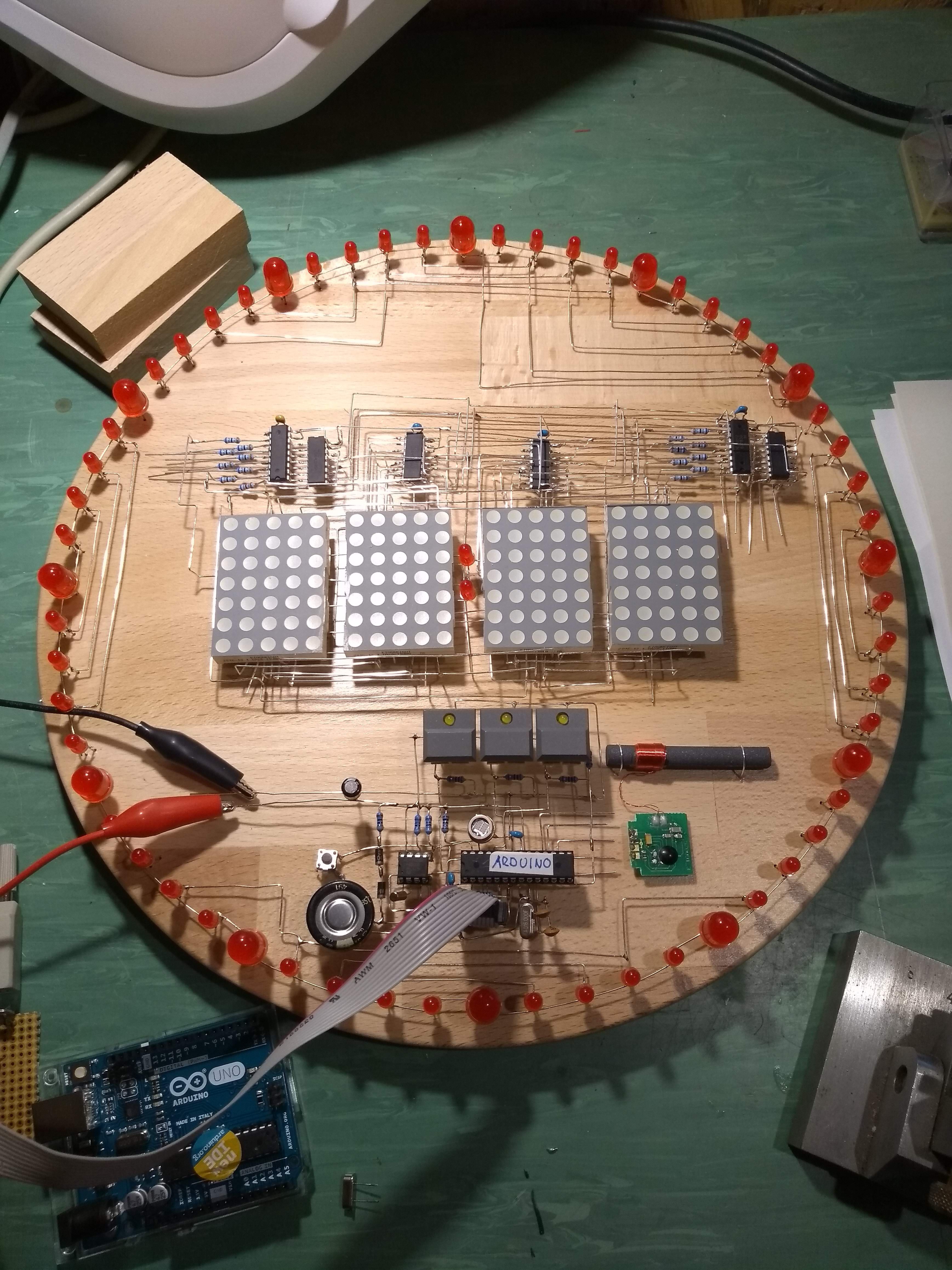
At the moment I'm trying to upload the software. This seems more difficult than expected. But I keep on trying... :-)
Discussions
Become a Hackaday.io Member
Create an account to leave a comment. Already have an account? Log In.