Kelly Heaton
-
Electronic Naturalism
02/04/2020 at 02:50 • 0 commentsNaturalism is a philosophy of observation concerned with seeing deeply and without artifice. In the context of art, we typically associate naturalism with scientific illustration —a faithful rendering of visual reality, but an incomplete portrait of a world that also exists in ways not visible to the human eye.
Fortunately as an artist (less inhibited than a scientist), I am free to expand naturalism with other modes of sensory perception. I use electronics to enhance my visual studies of nature because electricity enables me to work on the level of waveforms.
Waveforms are the basis of everything. If you isolate a fundamental particle in a vacuum, it is not a static entity but a sinusoidal wave function. This is a beautiful mathematical truth of the universe.
When such a particle is exposed to other particles, they combine into a system with a unique wave function for which complexity increases dramatically with each new member. In other words, reality is build from wave functions oscillating in relationship.
My work is inspired by this naturalist view of the universe. Using analog electronics, I build interconnected oscillators to generate life-like waveforms that can be experienced as sound and light. These studies do not use recordings or digital logic — the effects that you witness are generated by my circuits. You can watch how I experiment to discover interesting sounds:
Consider this transparent bird, which contains an oscillating circuit that you hear and see on my oscilloscope:
The following work uses the same type of oscillating circuitry to create the sound of squawking parrots:
I’m fascinated by the complex waveforms that I can generate with a handful of low-cost electronic parts. What, if anything, do analog circuits teach us about the brainwaves of a chirping cricket, frog, or singing bird? Given that a few interconnected oscillators can make a bird-like song, what amazing patterns arise from thousands or millions of vibrating elements? I have a hunch that the origin of consciousness is, on a fundamental level, similar to the oscillating circuits in my electronic studies of nature.
-- Kelly Heaton, February 2020
-
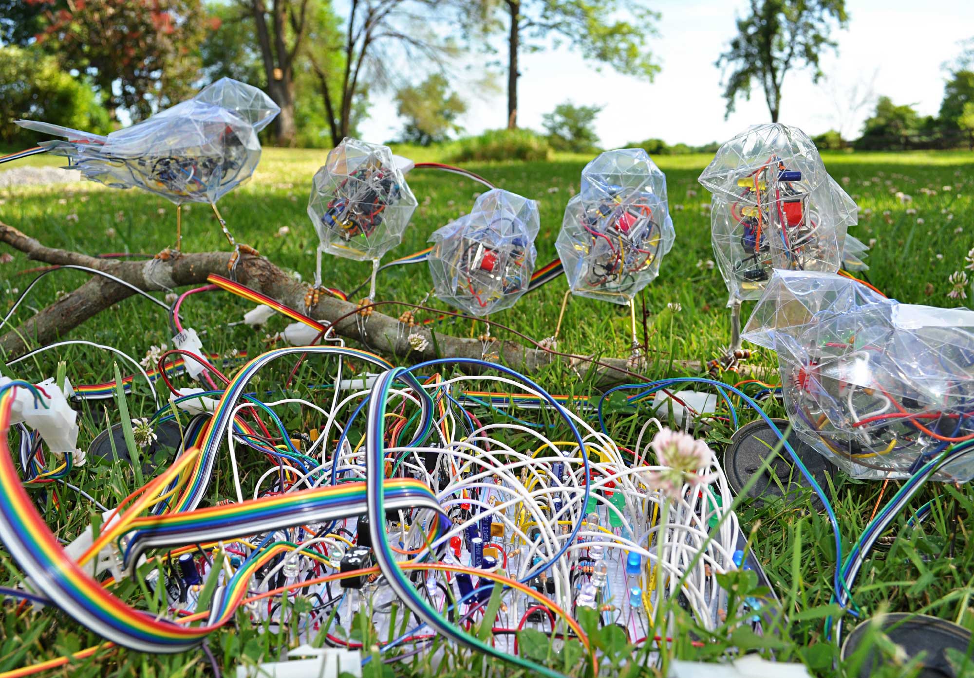
Birds at My Feeder (WIP), 2019
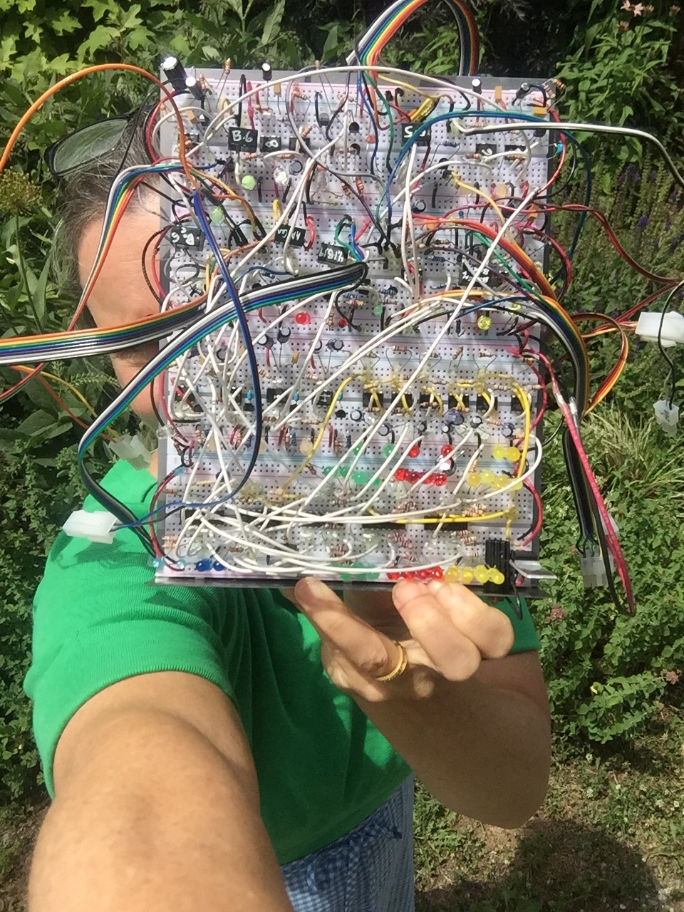
08/13/2019 at 15:26 • 0 commentsFor almost a year, I've been working on a large sculpture called "Birds at My Feeder," (2019). It remains in various pieces until I find a suitable exhibition venue. Meanwhile, I took the analog electronic songbirds and controller (breadboard sequencer, see below) outside to shoot this video. Check out my other videos on Vimeo (or read through my recent blog entries) for more information about these singing circuits and individual birds.
![]()
![]()
![]()
-
Moth Bus
04/08/2019 at 23:53 • 0 commentsAbout a year ago, I created a sculpture titled "Moth Electrolier" (2018) in which I used animated LEDs to represent the trails of moths flying around a bulb at night. Here's a video on Vimeo:
This post is about the design of a bus to drive trails of individually addressable LEDs using only hardware (discrete components, no software).
In artistic words, I made moth trails in the form of animated light.
First, some background info...
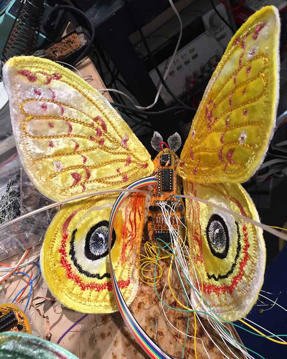
![]()
For my sculpture "Moth Electrolier (2018)," I made my own flexible circuit boards to animate 50 LEDs using 4017 chips and some astable multivibrators. My custom LED controller boards (not detailed in this post) double as sculptural bodies for the large moths with embroidered wings. As seen in the aforementioned video, each large moth acts as a controller for the long white trail of LEDs that spills out of its backside.
![]()
If you want to make your own LED controller from discrete parts, search for the iconic "Knight Rider circuit" and go from there. If you want to CNC embroider your own moth wings, you can read about my process here.
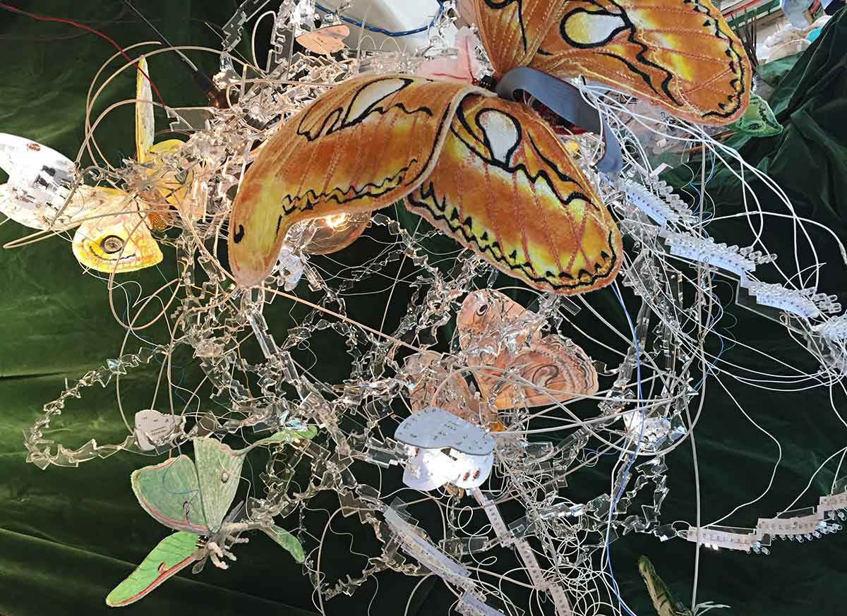
Even with flexible PCBs, my 2018 "Moth Electrolier" still needed extra hook-up wires to drive the LEDs because I couldn't elegantly fit all of the necessary traces on two sides of the board (and more layers are $$$). Because I soldered the flexible circuit boards end-to-end, each controller is trailing 100 LEDs plus a minimum of ten wires... and sometimes more wires to solve whatever unexpected real-world problems I encountered. The resulting chaos looks crazy-cool (like crazy flying moths) so I was fine with that.
![]()
The design for an individually addressable bus of LEDs is not new, and you can buy an off-the-shelf solution from any number of manufacturers. However, I wanted control over my own LED bus design for several reasons:
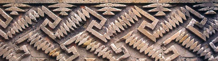
(1) AESTHETICS. In my case, I was inspired by a design that I saw at the magnificent ruins of Mitla in the state of Oaxaca, Mexico;
(2) HUMAN SCALE. It drives me crazy that so many manufacturers insist on teensy surface mount components. I know that miniaturization is useful for a lot of applications, but as an artist who makes things by hand, I want parts that I can see and touch -- especially now that I wear reading glasses. I love big, chunky, sculptural electronic components. 5mm through-hole LEDs lend a sculptural dimension to my moth trails that would not happen with surface-mount parts;
(3) POSTERITY. I used 2-pin headers for the LEDs so I can easily replace them when they burn out. If my sculpture is purchased by a collector who keeps it blinking 12 hours a day every day, the LEDs will die in about a decade. That's not a long time where art is concerned. Can you imagine replacing several hundred of surface-mount LEDs in a delicate sculpture like this? Yikes.
So... while my flexible circuit boards used for "Moth Electrolier (2018)" are functional, I made one annoying mistake from an engineering perspective. As previously mentioned, I was inspired by these awesome rectilinear designs at Mitla:
![]()
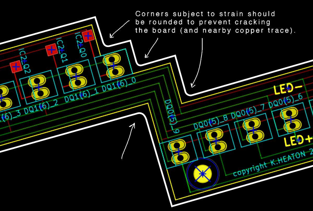
That's all well and good, but I should have placed a small curvature at every corner where my flexible circuit board experiences physical strain:
![]()
I hope that you will avoid this mistake in your designs. Flexible PCBs move. Expect mechanical strain. I managed to stabilize my boards with a tiny dab of glue on both sides.
... and that leads me to my current design and contest submission....
At first, I considered submitting a redesign to Hackaday's Flexible PCBs competition, but the contest reward is limited to a board size of 2 square inches or less and my original board design is 17.5 inches long -- a PCB behemoth. Luckily, constraints are often the mother of invention. I'm still ballooning outside of 2 square inches, but at least the Hackaday contest constraint got me thinking.
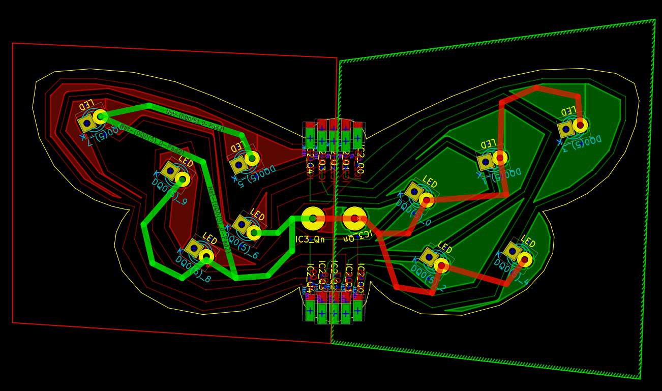
Here's a screenshot of my latest approach to a moth bus PCB, which measures 1.75 x 4 inches. Yes, I could make it smaller but then the moth wings would be so tiny and sad! No.
![]()
(My apologies for the KiCad fill zones borders being visible in this screenshot.)
My new design is a single "moth bus" unit for addressing up to 10 LEDs with an external controller. My board features solder pads on the moth's head and tail enabling these units to be daisy-chained for as long as desired, or until the resistance of the copper gets too high.
For the literal-minded among you: this board is a single unit for addressing 10 LEDs via an external controller. For a longer bus / more LEDs, solder these units end-to-end.
For the artistic among you: yes, you can make almost any circuit board into a cool shape.
If you're very observant, you might be wondering why I placed two pads called "IC3_Qn" for connecting only one extra wire. It's because I plan to use these holes to physically position the moth's wings. I've spaced them a little further apart in designs that are slightly more recent than the one pictured here in order to give myself a more mechanical leverage.
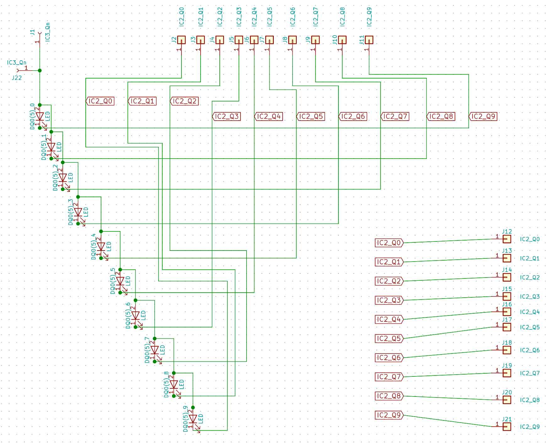
Here's my quick-and-dirty moth bus schematic:
![]()
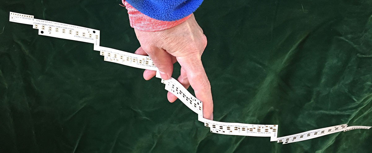
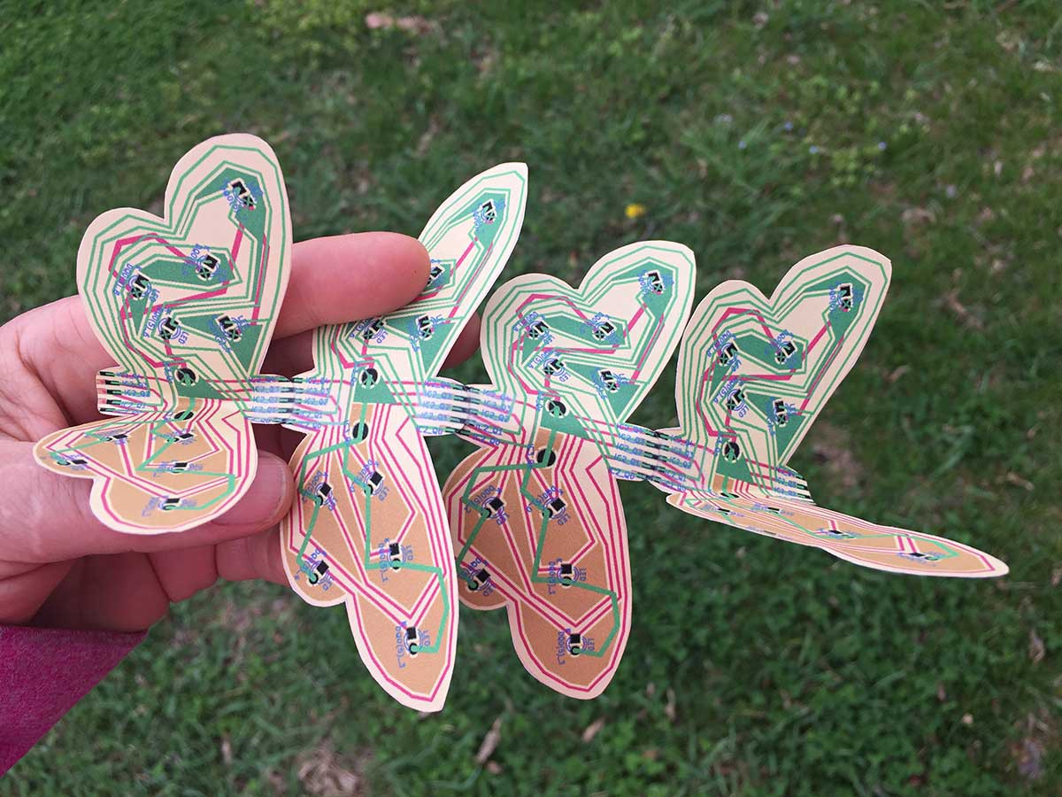
Here's a photo of a scale paper mock-up that illustrates how my moth bus will look when four units are soldered together:
![]()
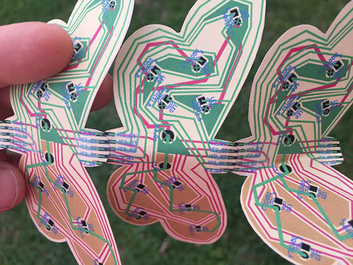
And here's a close-up illustrating the end-to-end solder pads that should, in theory, connect the moth bus to make a long strand of individually addressable LEDs:
![]()
As you can see from my paper mock-ups, a flexible circuit substrate enables me to position the wings in space (along with their associated LEDs).
Hopefully it's evident why my board design exceeds the 2 square inch requirement: my moths *are* sculpture -- they are meant to be seen. Visible electronics are a critical dimensions of my art. I don't want to make teeny tiny moths that are barely visible.
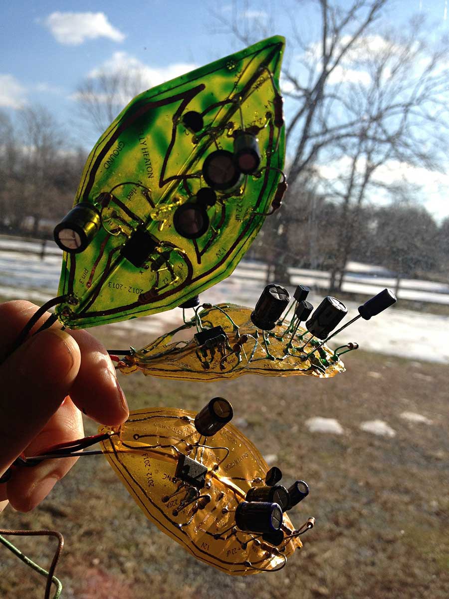
I would also like to manufacture these moths without solder mask because I really like the see-through effect that a flexible PCB substrate offers. Concerning the relationship between PCB transparency, beauty, and nature.... here's a photo of a leaf that I designed in 2013 and manufactured myself using nasty home-brewed ferric chloride etching:
![]()
If you're wondering about the green color on the top leaf, I painted that on after I made the board. (The green paint is translucent because I added medium-bodied acrylic medium.)
+++
Last but not least, if you like my work, please give me your vote towards the 2019 Hackaday competition. While my work can hardly be called "product design," the world would be a very boring place with only products and no art.
Thanks!
-
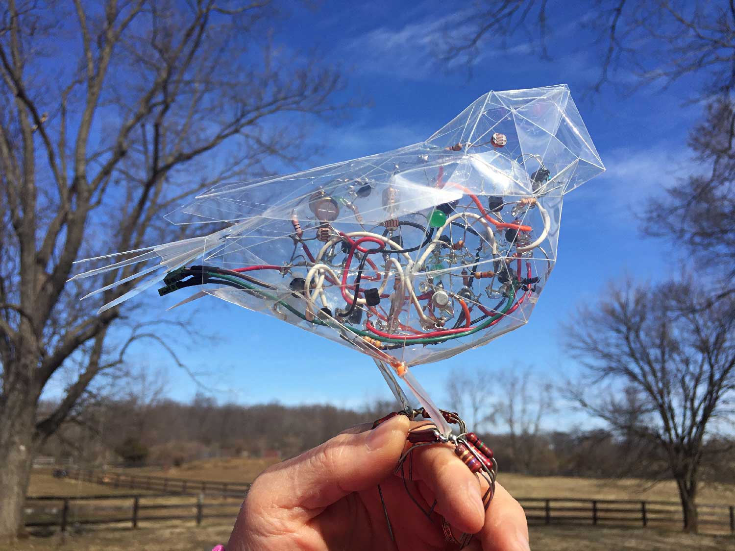
Pretty Bird
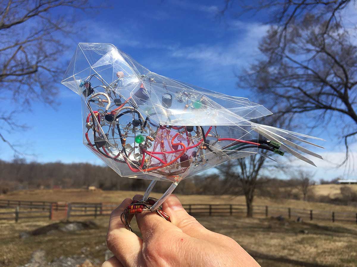
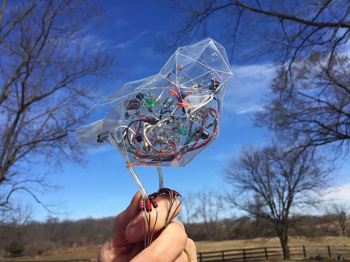
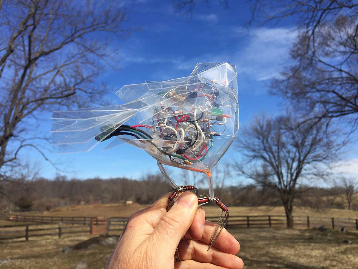
03/11/2019 at 17:31 • 0 commentsI am making sculptural, chirping bird circuits as part of a larger work in progress. Technically speaking, the circuit below (as seen inside of the transparent mylar bird) is an analog electronic chirp generator with a light-sensitive resistor. All of the electronic components are discrete -- no software or recordings. Notice how its chirp quality changes according to the amount of light seen by the photo-resistors. When the lighting conditions are favorable, the circuit sings "pretty bird." As you can see in the first video, the bird does not always change its song when I cover its photoresistor. That's because I have an LED coupled to the sensor -- so when the LED is turned on at various points during the oscillating cycle, my actions are irrelevant (because the photoresistor "sees" light from the LED).
Below is a video of another electronic bird sitting on a coffee cup at my bench.
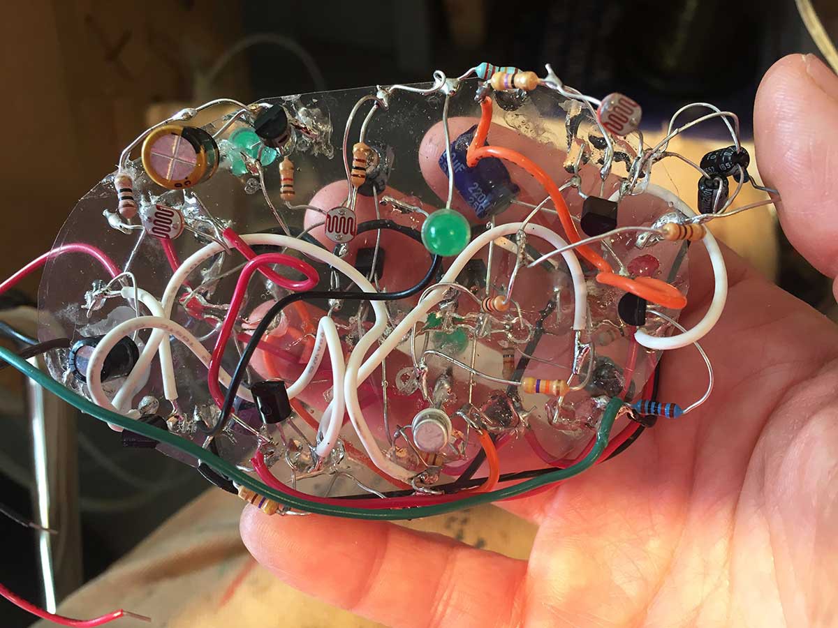
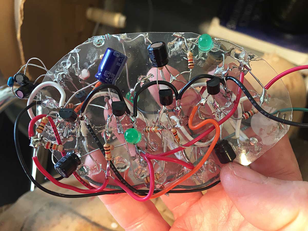
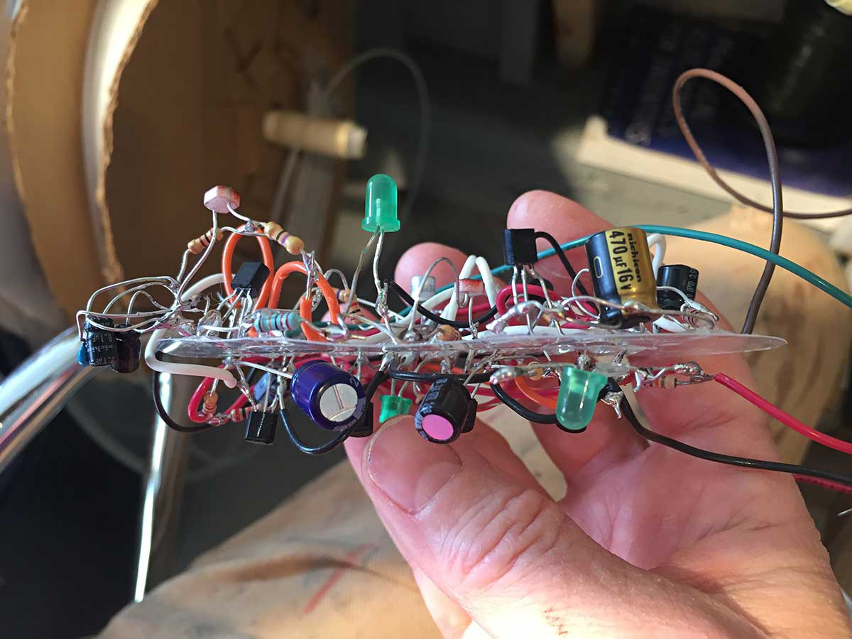
My art is about the spark of life and what creates it. Therefore, I do not want to hide my electronics in a box: my circuits are meant to be seen. Yet, as an artist who makes work for exhibition, I need to protect the delicate parts from years of dust, audiences, and transportation. Using techniques from paper crafting, I came up with a way to make a sculptural transparent shell. I also devised a method to stabilize my freeform soldering onto a transparent Mylar substrate. Here are some images of the circuit prior to insertion in the bird's body:
![]()
![]()
![]()
![]()
Some images of the bird after assembly:
![]()
![]()
![]()
![]()
I may turn this sculpture into a kit that you can build yourself. Message me if you'd be interested: info (at) kellyheatonstudio.com
-
Singing Mama with Baby Bird
01/08/2019 at 00:13 • 0 commentsI've built artistic circuits for years, but when the Hackaday challenge came along, I took it as an opportunity to build a purely sculptural circuit. I was intrigued by the challenge to ditch all forms of 2D and go completely freeform. (Incidentally, non-traditional planes for embedding electronics, like paper and canvas, are a great way to make electrified paintings. Totally freeform circuitry is an eccentric labor of love... but then again, so are all forms of art.)
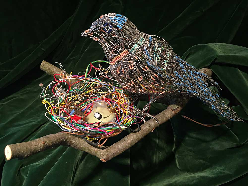
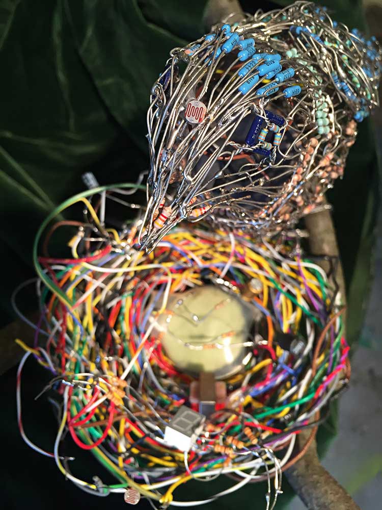
Here's what I ended up making for the contest, a mama bird with her baby in a nest:
![]()
Disclaimer: the branch is wood, but I had to put the nest on something... and I preferred the contrast of a natural material over a piece of wire. I could have put them on a big electrical transformer, like some birds do for reasons I can't understand, but I didn't have a transformer handy.
However, I do own loads of surplus resistors in different colors, collected over the years, which I use to create mosaic effects in my art. If you want a similar aesthetic, don't buy new resistors -- get some old surplus components and/or unsorted resistors for cheap. You can always measure them (and combine them in series or parallel) if you want to use them in a functional circuit.
The shape of the mama bird is made entirely out of resistors and she's hollow inside, which is where I carefully, painstakingly installed her freeform singing circuit. The baby bird is nestled in a nest of wires --not altogether different from the real thing-- and the light-colored object in the nest is an 8 ohm speaker wrapped in heat-shrink tubing (to mechanically dampen the sound). Both birds have a photoresistor that enables you to interactively affect their chirping. Here's a video showing the pair making their avian sounds:
I used a small segmented display to visualize the baby bird's yapping beak. I love how it "shuts up" when you wave your hand in front of the photoresistor. I have uploaded my baby bird schematic to the project files so you can check out how I achieved this effect using discrete hardware components.
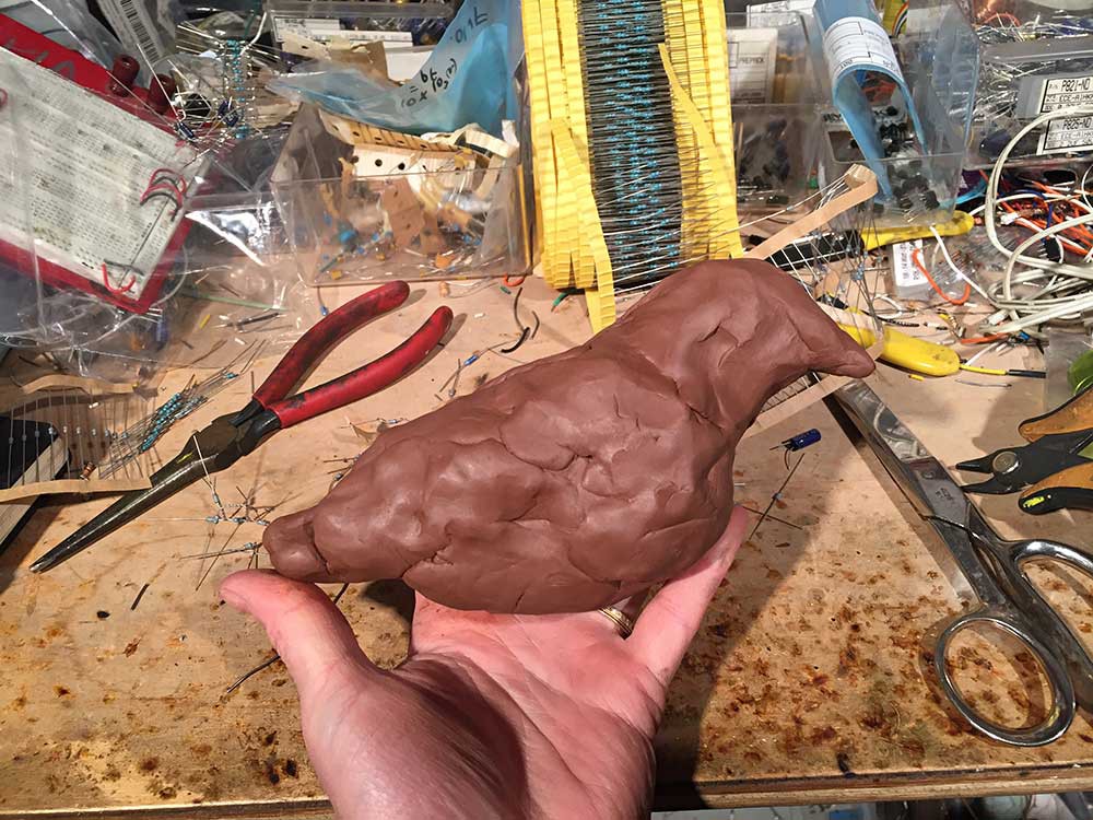
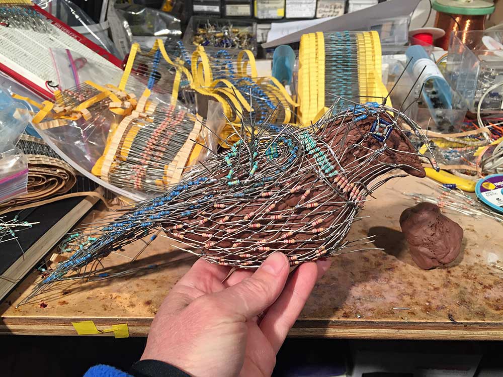
The mama bird's form was time-consuming and required two types of jig. First, and most importantly, the overall shape of her body: it's very hard to create a complex shape from hundreds or thousands of resistors without some guidance, especially because wires are prone to deform and collapse inward on a volume. After some experimentation, I discovered that regular modeling clay is a great substrate around which to form and solder electronics. Don't use plasticine clay - it will melt if you solder near it.
Below are a series of photographs showing how I made the shape of the mama bird:
![]()
First, I modeled her rough form in clay. The volumetric proportions must be accurate, but the details don't matter -- you'll use needle nose pliers to shape the final touches when your wire sculpture is nearly complete. Don't cut corners on the basic volumetric form or else your fundamental proportions will be wrong, and that's hard to fix.
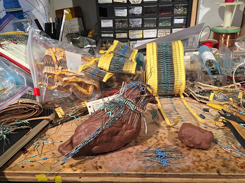
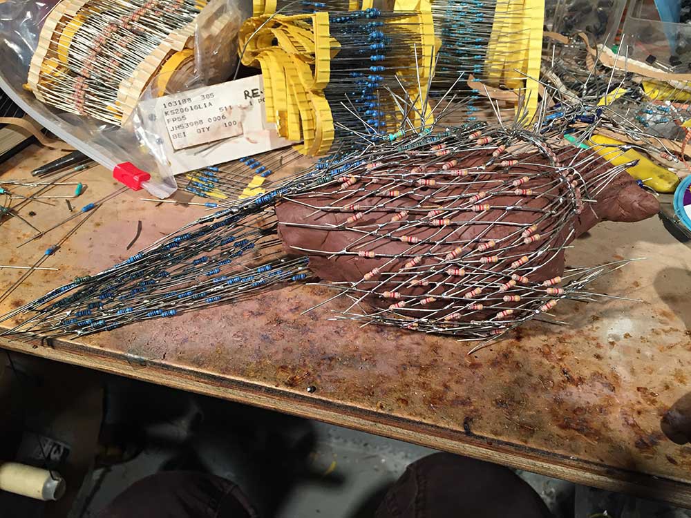
Next, I arranged resistors on the surface of the clay form and soldered them with the aid of a jig (more details on the second jig in a moment). Press the resistors into the clay to hold them steady. Natural clay is a great substrate onto which to solder, assuming it's not too wet and mushy. Don't worry about getting your resistors dirty, because you can wash the sculpture gently before you add active components (just leave time to dry if you plan to use the sculptural resistors as part of a functional circuit).
![]()
![]()
![]()
I played around with different patterns to define regions with texture as well as color.
As you go along, leave yourself an opening to remove the "resistor shell" from the clay form. I left a seam along one side, underneath the bird's wing, where it would not be visible in the final piece. I also used this seam to insert the functional electronics inside.
![]()
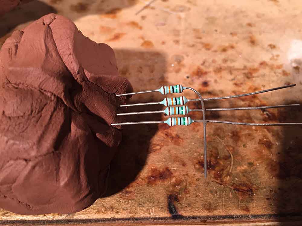
Now for the second jig: if you try to solder together a bunch of resistors (or whatever) lying freely on your bench, they are prone to move. That's another great application of modeling clay: see the small blob sitting on my bench to the right of the bird? I used it repeatedly to hold resistors in a pattern so that I could shape and solder them. Clay is a really great way to hold parts in place. Mash it into whatever form you need.
![]()
So that's how I made the form of the mama bird. It took me several days. Each night I would remove the clay form from the wireframe and store it in a sealed plastic bag (so it wouldn't dry out). If you keep the clay damp, you can reuse it indefinitely.
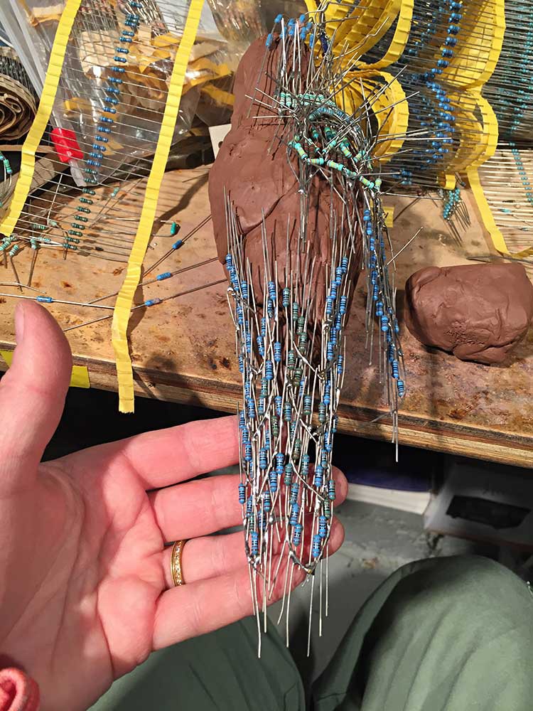
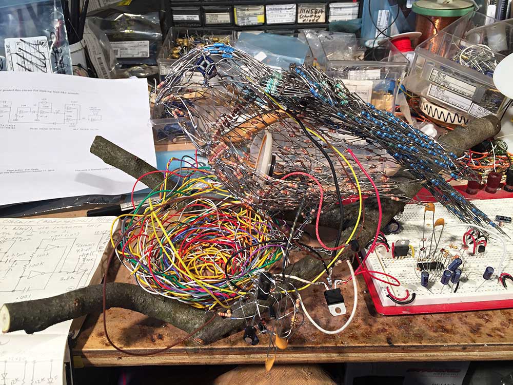
Below is a photo after I finished sculpting the mama bird on the clay jig and opened her along the seam to insert the functional electronics. (Her circuit was based on a bicore design by Wilf Rigter).
![]()
Unfortunately, it's hard to see what's going on with so much complexity... but if you look along the underside of the wing you can see a horizontal opening that runs from the base of her belly to the tip of her beak. I left several longer, unsoldered leads along both edges of the seam so I could twist them shut without soldering (in the inevitable case that she needs to be opened for repair).
An interesting side note on making a complex sculpture out of linear electronic components: remember Thevenin's equivalent? Find any two points on the resistor network, measure them with your multimeter, and voila -- you have a resistor of known value at your disposal. I didn't end up tapping into her body for resistance, but I certainly could have done this (and probably will on future projects). I did insert the photoresistor into her head though, like the third eye that bird's reportedly use for long-range navigation. You can see a detail of that below.
Thanks for reading! Ciao for now.
![]()