 Sander van de Bor
-
1Upload the sketch and set fuse to disable reset
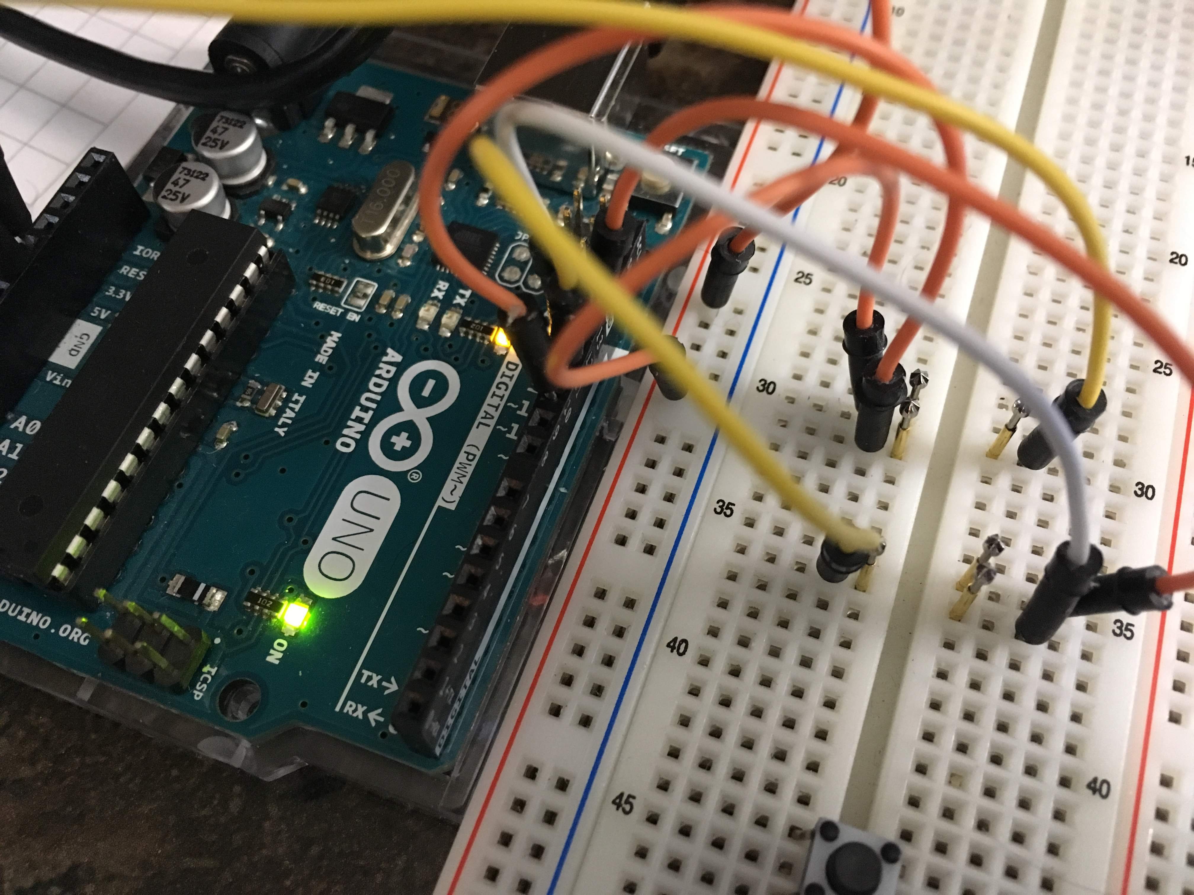
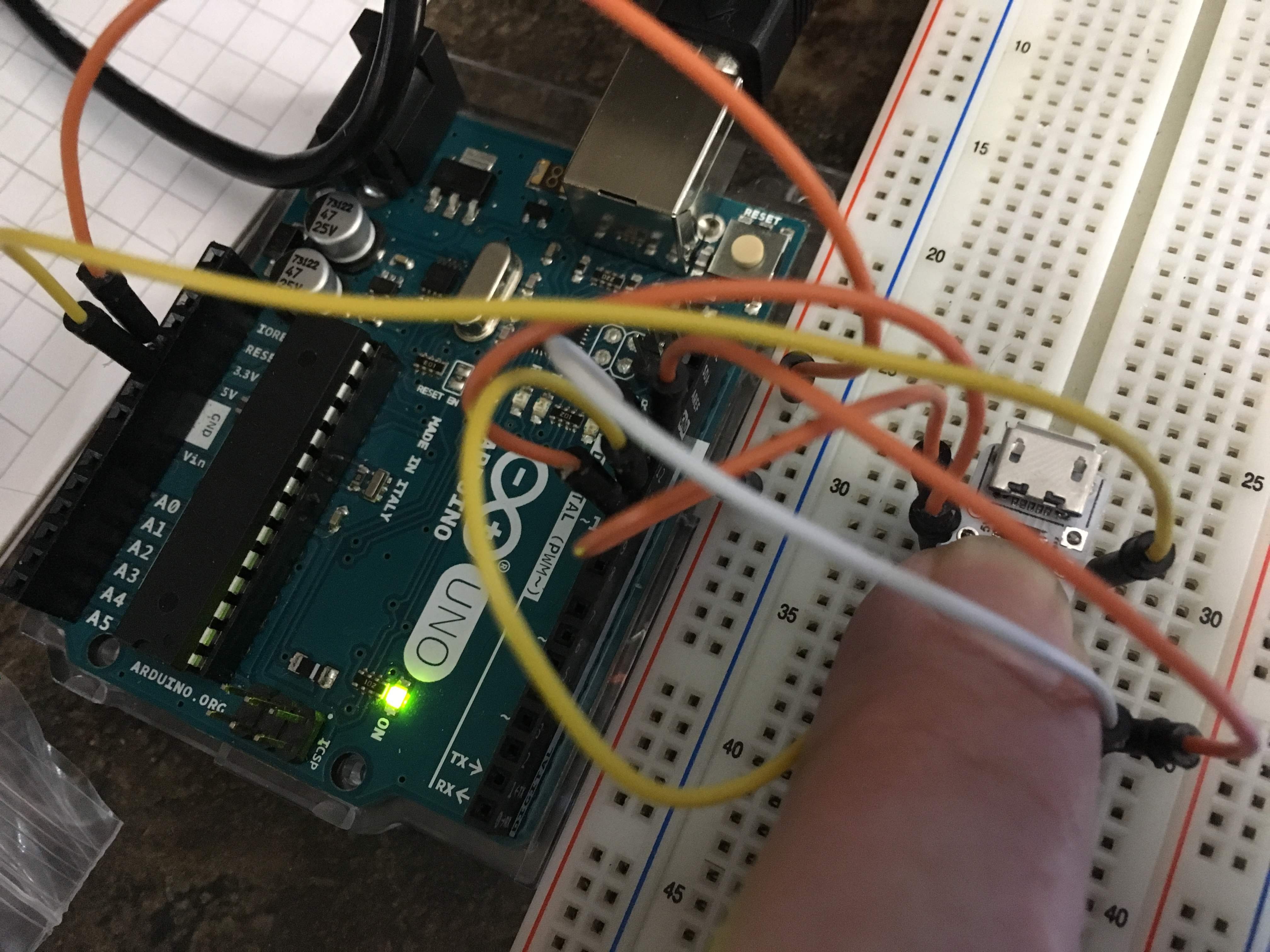
Upload the sketch using the Arduino UNO as SPI programmer. Use 1mm diameter pogo pins to connect to the board:
![]()
![]()
Set the clock to 1MHz (internal), this will reduce the power consumption, we do not need speed. Upload the following sketch:static byte timerDelay = 255; bool timerDirectionUp = false; void setup() { DDRA = 0xFF; // Set all pins on PORT A to outputs PORTA = 0x00; // Set all outputs to LOW DDRB = 0x0F; // Set all pins on PORT B to outputs PORTB = 0x00; // Set all outputs to LOW cli(); TCCR1A = 0; // Timer/Counter Control Registers TCCR1B = 0; // Timer/Counter Control Registers TCNT1 = 0; // Timer Counter //OCR1A = 3906; // Output Compare Registers 0.256 * 3906 = 1000ms OCR1A = 30; TCCR1B |= (1 << WGM12); // Clear Time and Compare CTC TCCR1B |= (1 << CS12); // 256 prescaler 1Mhz/256 = 0.256ms TIMSK1 |= (1 << OCIE1A); // Output Compare A Match Interrupt Enable sei(); } ISR(TIM1_COMPA_vect) // timer interrupt { if(timerDirectionUp) { timerDelay++; if (timerDelay > 200) timerDirectionUp=false; } else { timerDelay--; if (timerDelay < 5) timerDirectionUp=true; } } void loop() { cli () ; // Turn off interupt PORTA |= (1<<0); // set pin 0 (PA0) to HIGH __asm__("nop\n\t"); // Wait for 1 clock cycle PORTA &= ~(1<<0); // set pin 0 to LOW PORTB |= (1<<3); // set pin 11 (PB3) to HIGH __asm__("nop\n\t"); // Wait for 1 clock cycle PORTB &= ~(1<<3); // set pin 11 to LOW sei () ; // Turn on interupt delayMicroseconds(timerDelay*10); }After uploading the sketch, disable the reset fuse in CMD (find your settings in the Arduino verbose output):
C:\Program Files (x86)\Arduino\hardware\tools\avr\bin>avrdude -CC:\Users\username\AppData\Local\Arduino15\packages\ATTinyCore\hardware\avr\1.2.2/avrdude.conf -v -pattiny84 -carduino -PCOM3 -b19200 -Uhfuse:w:0b01010111:m -
2Solder the LED's to pin 0 and 11
I picked pin 0 and 11 since these are the closest to the USB connector (head of the spider) after the 5V and GND. 5V and GND are used for the first legs. Unfortunately pin 11 is the reset pin and for that reason the reset was disabled in step 1 so that it can be used as an output.
![]()
The anode leg (+, long leg) connects to the outputs pin, the cathode to the top of the USB connector. The entire USB connector is connected to ground. Trim the legs, but keep the trimmed ends. -
3Solder the legs
Solder the resistor, sticking out from the top on pins 5V, GND, 1, 3, 5, 6, 8 and 10.
![]()
Bend the legs slightly so that it can stand.
-
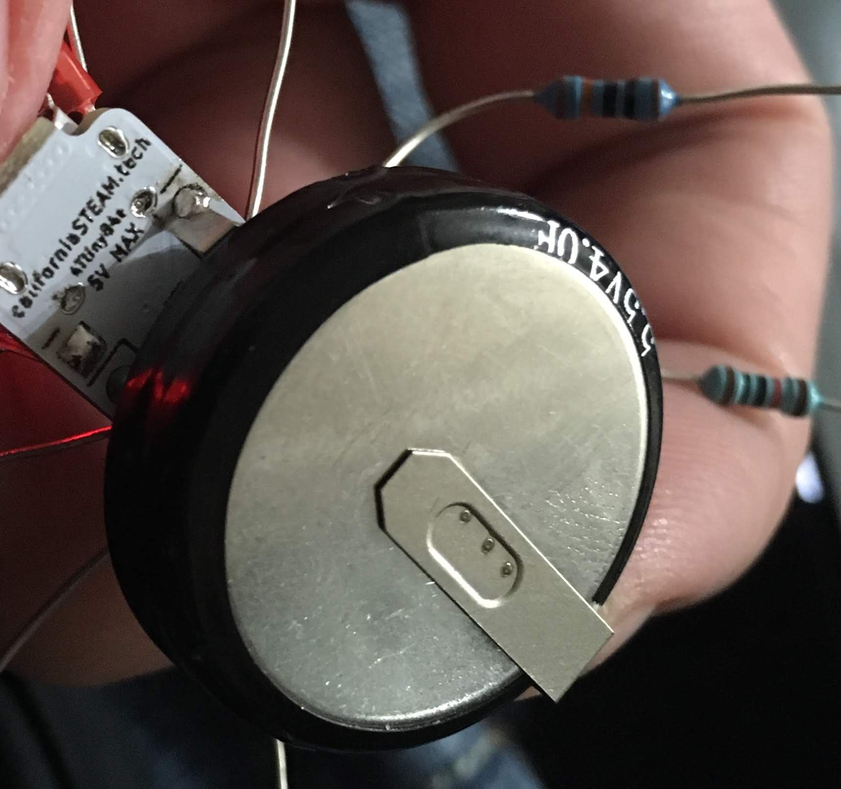
4Solder the super capacitor
Apply some tape to the bottom of the capacitor to avoid it from creating a short to the board.
Solder the 5V side of the capacitor to the 5V pin on the board:
![]()
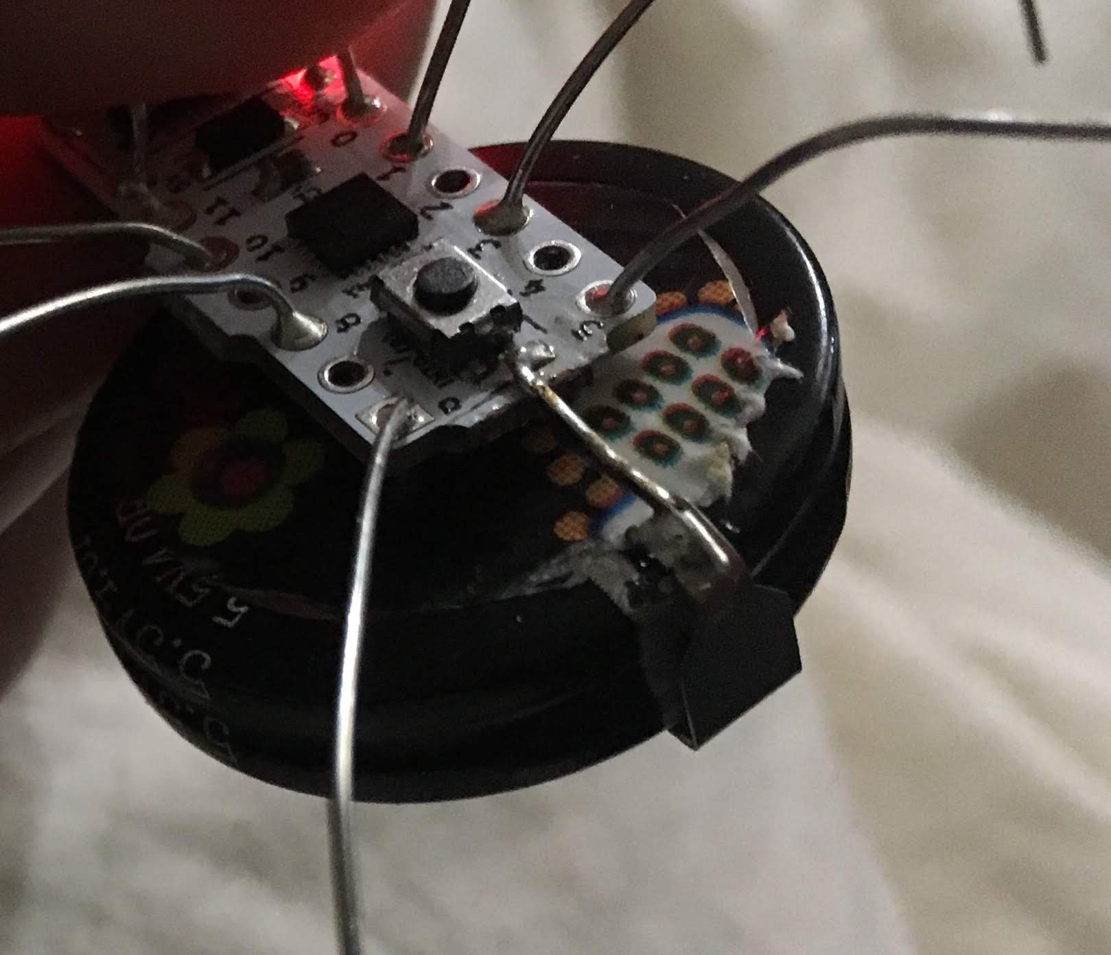
Use the scrap piece from the LED leg to connect the GND of the capacitor to the back of the board, next to the push button. Push button is connected to ground at the side of the board.
![]()
-
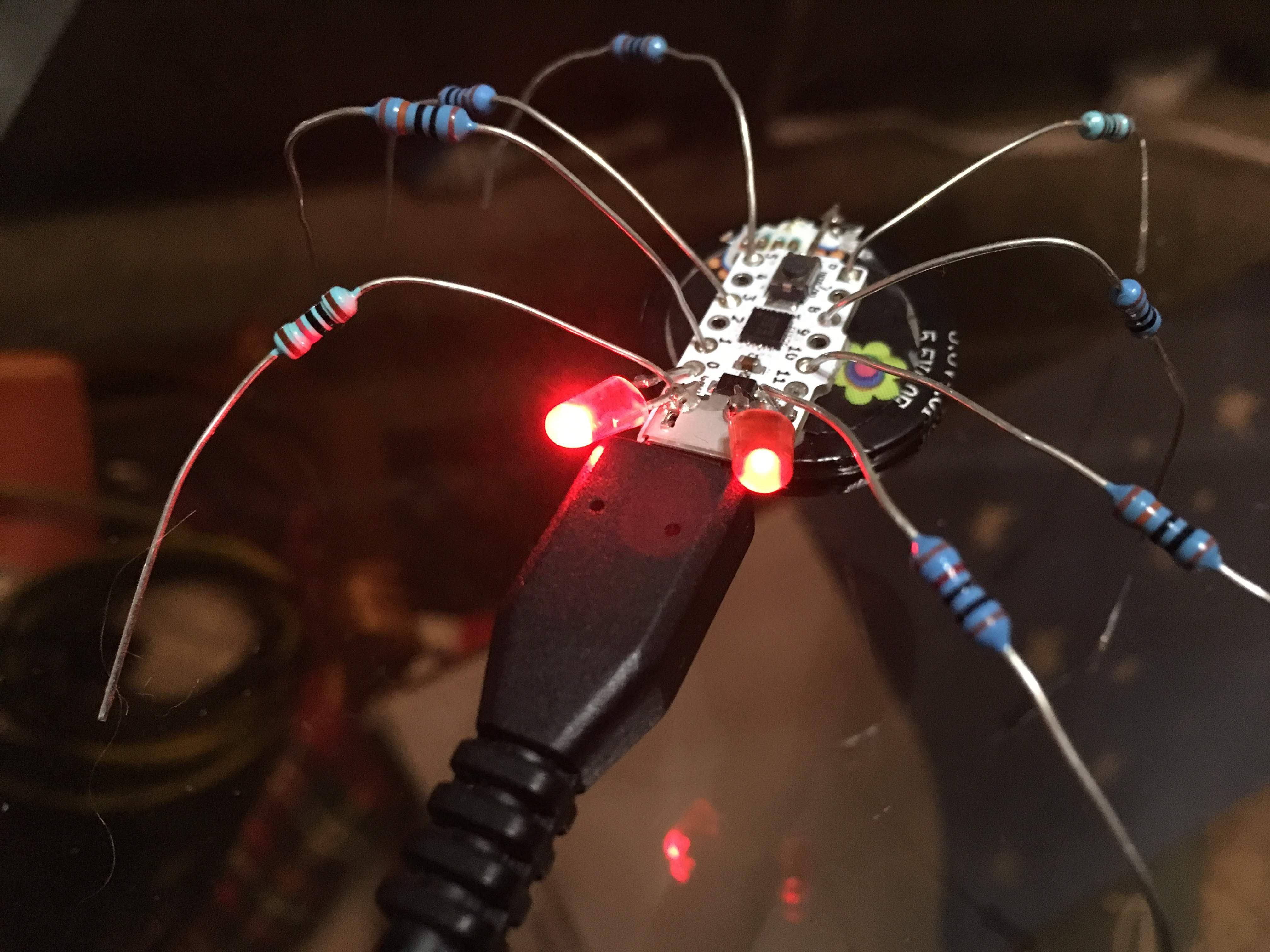
5Charge the super capacitor and enjoy the glowing eyes
Charge the super capacitor with a micro USB cable. Charging should only take a couple of minutes, but it will do no harm when charged for longer times (super capacitors will just stop charging when they reach full capacity).
![]()
Disconnect after a couple of minutes and enjoy the spider with glowing eyes.
ATtiny Super Capacitor Spider
Little spider with glowing eyes powered by a super capacitor, and controlled by an ATtiny84a


Discussions
Become a Hackaday.io Member
Create an account to leave a comment. Already have an account? Log In.