Tobius
-
Update 15-08-2019
08/15/2019 at 06:00 • 0 commentsProject 3+Pi has been featured on a Hackaday article here. As soon as I heard about it, I could not help but feel so overwhelmed with joy seeing my work being acknowledged! Thank you Tom and the rest of the hackaday team for that. I am very humbled. :D
On to the updates of 3+Pi. I'll be honest, there hasn't been any update so far since I've been working on StuPD which honestly has been very, very slow. I have been bogged down with my usual Engineering 9-5 job which hardly gives me time to work on these projects.
After seeing the comments talking about how to integrate it with klipper3d and adding limit switches, fan drivers and heaters (for a 3D printing setup to which I completely forgot about! Unbelievably so.) I will have to revamp the design to add those on board.
I'd like to work on some additional features/modifications such as:
- Modifying the powersupply unit to accommodate both USBC and DC barrel.
- Test it's compatibility with the Raspberry Pi 4 and power it too
- Expand the board to allow more heat sinking for the drivers, thus exceeding the template I used from KiCAD.
- And others I have to sit down and think about.
As the article mentions and I mentioned earlier, I am looking for any help externally should they wish to help out. There is a lot if so much, to do on the software side of things. Speaking of which, the Rpi3B+ has a 'shared' UART with the BLE/WI-FI module which makes it annoying so I have to compensate for that.
In addition to all this and perhaps more of a madman idea:
I'd like to make a custom SBC unit that can support the 3+Pi alongside creating a proper eco-system of a standalone 6DoF, multi-functional device to fit the need.
Now that is not easy and to be honest, I'd want to work on that AFTER I've carefully done lots of tests with 3+Pi entirely. However, It's something I've wanted to do for a while now and cannot find any perfect use of an MPU (Thinking of A53/A57 units..maybe perhaps RISC-V? hmmm) for something other than a breakout board similar to any other pi.
Thank you again everyone for following this project and your feedback. I will do my best to keep updates and see if there will be any progress later. But I must iterate that I hardly have time to spare... But I'll still do something.
-
Introducing Spine for 3+Pi
04/21/2019 at 14:03 • 0 commentsHi everyone.
I've finally made the Hackaday page for Spine. Here it is: https://hackaday.io/project/165110-spine-for-3pi
Parallel to working on the 3+Pi, Spine will be an optional unit for closed loop 3D space sensing. Ideally to be used with the 3+Pi, I plan on releasing the designs for anyone anywhere to use it.
Thanks, have a good day!
-
Minor Updoot 09-04-2019
04/09/2019 at 01:27 • 0 commentsHello.
I've been busy lately and haven't gotten much time to work on the Spine board yet. I will get to it as soon as I can while I sort some normal day chores out first and get sometime.
In other news, 3+Pi has entered the 2019 Hackaday competition! woo! So many amazing project entries from others which is really awesome!
-
Feedback is nice
03/25/2019 at 06:57 • 0 commentsGood Evening.
So I was thinking about adding some sort Motion feedback from the motion created by the stepper motors allowing a closed feedback loop if the system is going to be used as a 3D space instrument.
Essentially it will be a plug in board which will be remounted onto a distribution board which will connect two sensors on each side whilst the distribution board contains a different yet similar approach to the other sensors.
Hmm, knowing that this will bump the pricing overall up, it will be an optional setting which is why it will be a 'plug in'.
Again with the close-no-budget that I have right now they will remain in software phase without any testing done in real-life. I am not sure if a go-fund-me or kickstarter would suffice because I don't know or like marketing exaggeration and my projects are very niche, let alone completely over saturated now times.
Oh well, if anyone would be interested in conversing about this, please send me a message/comment and I will hopefully get back to you very soon.
-
3pluspi.com now redirects to this page
03/12/2019 at 01:45 • 0 commentsMinor Updoot.
3pluspi.com now redirects to this very hackaday page.
Other than that, no changes or updoots. Still working on other stuff for now.
-
Updoot 26-02-2019 | Want to beta test?
02/26/2019 at 03:12 • 0 commentsGood evening.
The last few days have been quiet as I haven't done much. I am still looking for ways to get this funded to be released. I am not really that keen on doing over-the-top advertising and would prefer a small niche market anyway.
I'm always open to anyone willing to join the team, unfortunately I am not really a marketing person so I do not have the finances to pay for your time. I ---however--- promise to make it up for it later when something comes out of it and will be as transparent as the air that's between your eyes and the screen that you are using to read these texts... Assuming you're not in a smoggy area...or wearing sunglasses...or... Okay that was a terrible analogy.
If you're keen to be a beta tester and are willing to make your project using this board, feel free to contact me here by leaving a comment, sending me a message here.
Thank you for reading, hope you have a good day.
-
V1.3p Prototype designed! [Edited with more info]
02/17/2019 at 07:11 • 0 commentsOkay so major changes on the new board. I've changed project image to replicate that.
I'll add in the changes after making an actual change list with the project itself and the BOM cost.
Additional Edit [10-02-2019]
Good Evening.
Version 1.3p (p = prototype) has been designed with some massive considerations and changes whilst still keeping in mind of the the same concept of 3+Pi original idea. The reasoning behind these changes were to reduce the BOM Costs and try to optimise the maximum usage of components available. As you will notice later on the that the Components listing will change to adhere with these potential replacements.
They are as follows:
STM32F401RE ---> STM32F302CBT6
This is a 48 pin count lesser 'expensive' variant from ST Electronics.
May also make it obvious that this is a personal bias choice of mine because I happen to have a knock-off STLINK from ebay that will let me program with this chip. I would have loved to program with the Microchip's variants which have quite an appealing price. But not only do I not have a ICE board or the ace of all cards: JLink.
This drops the price by about $4.00AUD from Digikey listing (individual piece).
TMC2100 --> TMC2041-LA-T
This Trinamic chip contains dual Stepper driver modules in one chip. Not only is this great for space factoring but also I happened to have found that they also do use the SPI Ctrl system to drive the motors leaving me to use the SPI control mechanism of the STM listed above. Besides the fact that I limited the current to about .9A per coil, this should be plenty for small applications and less torque demanding applications. I will have to do some serious testing on this platform to make sure it works.
MAX17574ATG --> TPS54340DDAR
TI Chip allows more current to be pumped out without the need of external MOSFET drivers. I chose this for the sake of space and also reducing development timing. I will need to do some testing and see if things work out and if the supply is as regulated as expected and actually am recording the right amount of voltage. Which is why I used to 2.54mm jump headers to measure current draw.
With those changes made. Here are some new additions to the board:
---------- more ----------Optional MCU generated Clock signal (cheap option) for the drivers otherwise xtal dedicated (recommended). This can be selected by the solder bridge. The STM will have to use a 16MHz ext XTAL to and then it will pipe it out to a dedicated pin which drives a MOSFET at higher voltage allowing the need for current for other needs if necessary.
Optional 3rd Dual Stepper driver. Since the drivers are now connected to the SPI bus, the number of pins needed to drive them are lesser than to have them individually being driven by STEP/DIR pair. Two chips alone will grant you 4 drivers which should be enough for 3D printers with one single extrusion. Since the the third chip will grant another pair of drivers, 3+Pi can be used to drive a 6DoF application... I've also broken out the STEP/DIR pair for each driver if anyone wants to use that outsides the STM's control.
Optional CAN operation. I was inspired by the need of CAN and applications for it so I decided to put a CAN driver on the board since I had the space to put it. It is also terminated with a 120R 2512 Resistor. Obviously this can be removed if not needed. Both the IC and the terminating resistor. Will have to implement protocols for the CAN driver later on and see if I can get it to do 1Mbps comms.
USB-C PD Sink controller. The FUSB302B01MPX allows the 3+Pi to control the demanded voltage. This will be initially programmed to demand 20V at 5A (100W) maximum as basically a limit high power usb demand. Thus the TPS Bucks will regulate the 5V to the pi and driver logic while 3v3 for the STM board itself. It is rather unfortunate that I couldn't control the 3v3 rail for the pi but then again, I will lose the USB type A ports of the pi if I did so, that's fine I guess. With what the TPS claims, it will be able to power up the Pi with 5v pass through so hopefully there won't be any issues when it's connected to a USB 5V3A supply. The Driver enable pins are controlled by the STM which will be programmed to disable the drivers when the voltage is just not enough for the drivers to run at set current. I might even get a I2C potentiometer to set the current ratings on the coils... Hmm.. V1.4p perhaps?
That's about it for this revision. Thank you for reading. I hope to release new updates and possible if I can, get some funding to buy the new prototype parts without resorting to e-begging and obnoxious advertising/marketing. Thank you for your time. Have a great day and I hope you're inspired. :) -
Hmm... Something something USB-Type-C Power...
02/14/2019 at 12:41 • 0 commentsHmmm 100W MAX...
Negotiable power draw....
Potential reduction of e-waste by using current on the shelf power supplies.
Yup. I'm working on getting a power delivery mechanism working to allow USB-C Sink whilst taking advantage of that 100-60W power range. Fun fun!
... If only I had time :( bah! I'll do it anyway no matter how long it takes!
-
Updoot 09-02-2019
02/08/2019 at 14:38 • 0 commentsHello people of the internet...reading this.... hehe
Some major changes to the board. It's as if I went totally mental and threw everything from the table and started all over again... Except I did this by copying the folder and making a new prototype.
It obviously seemed like the F401RE was too expensive paired with 4x Trinamic individual drivers. This was seriously an issue I overlooked... because well I don't really have much time to work on this that much.
I've changed the MCU to the F334C6... Drivers to 2041-LA ... PSUs to TPS54340s. And also added a CAN transceiver since that 334 came with it. I've also had to reduce the pin count for the MCU so I can try to squash in as many stuff onto leaving nothing down.
Still planning on making it a 4 layer board too.
Well that's it for now.
Weekend sorted! I'll keep you all posted :D
As always, happy to have anyone who is interested to join and help out! Send me a message.
Cheers and have a good one!
-
Updoot 02-02-2019
02/02/2019 at 06:43 • 0 commentsHello again,
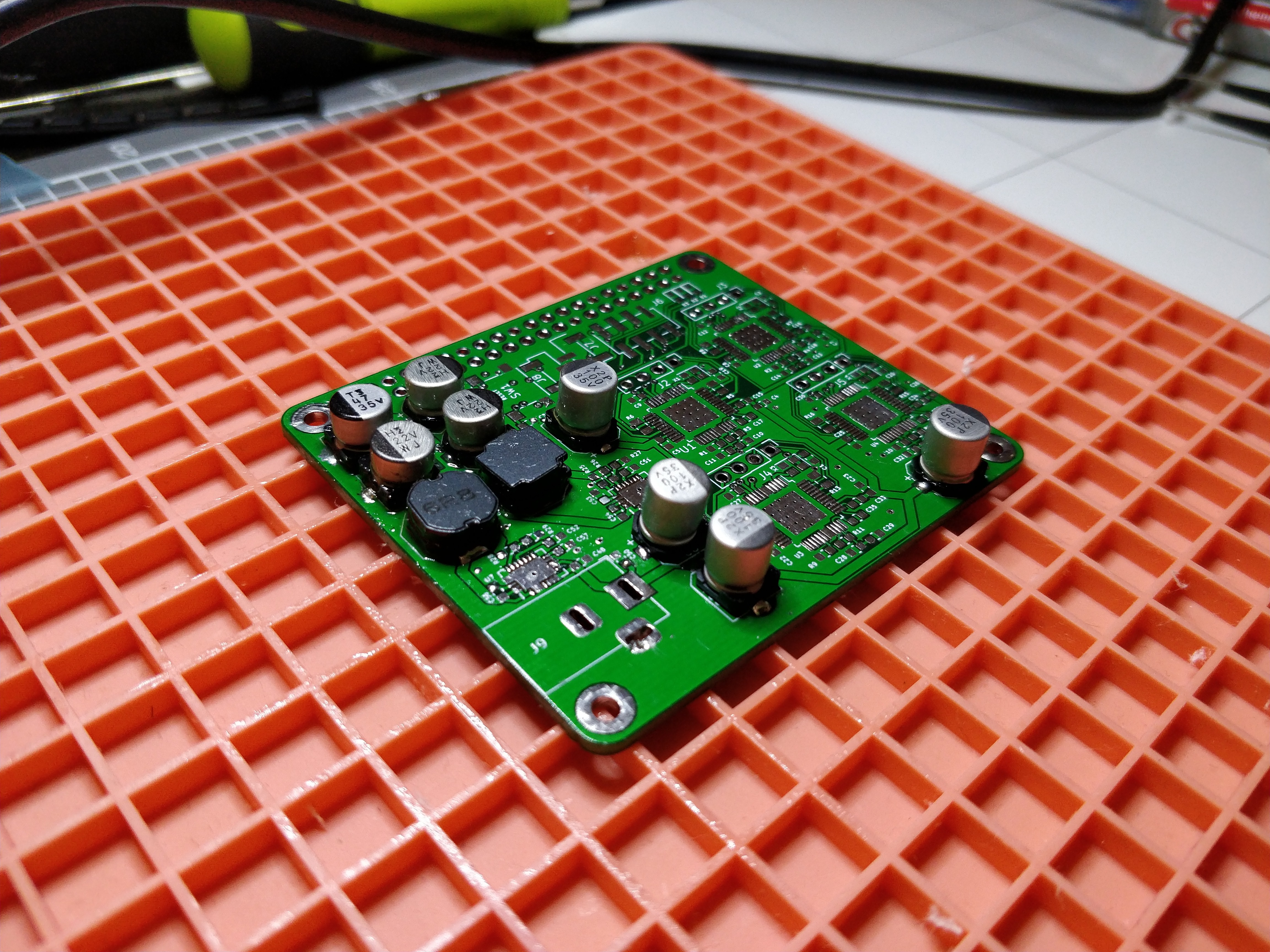
Got the digikey parts in, just now waiting for some parts from RS to come in and the first prototype board should be good! yay. Here is some progress:
![]()
Project 3+Pi
6DoF stepper motor driver module PiHat or standalone feature. Optional closed loop 6DoF sensing available too.