The Unruly specifications: Make it hack worthy
The Unruly is not just a crazy hack but is also a serious educational tool with lots of capabilities added to allow for experimentation. Here's the Unruly feature list in no particular order:
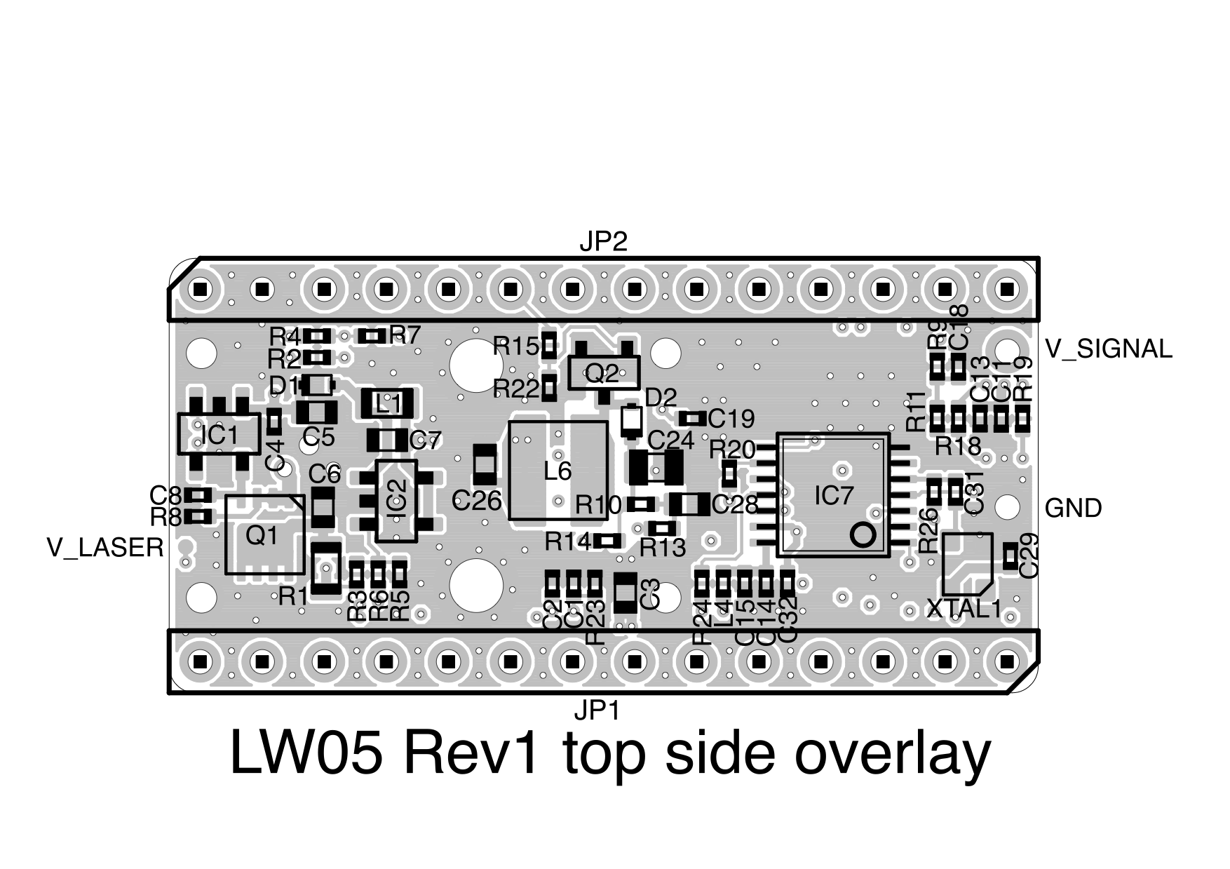
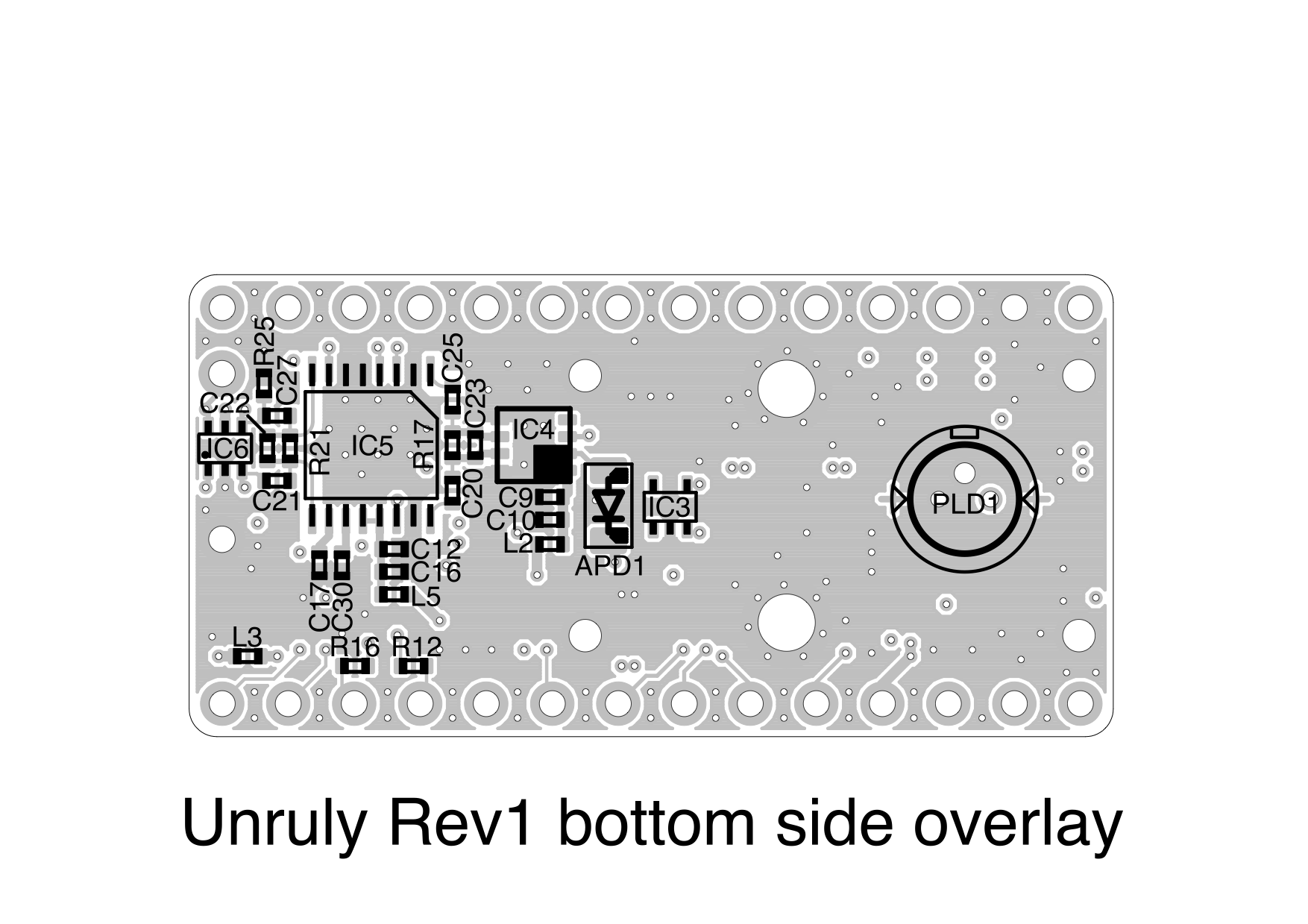
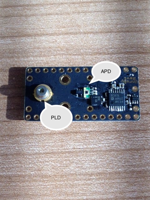
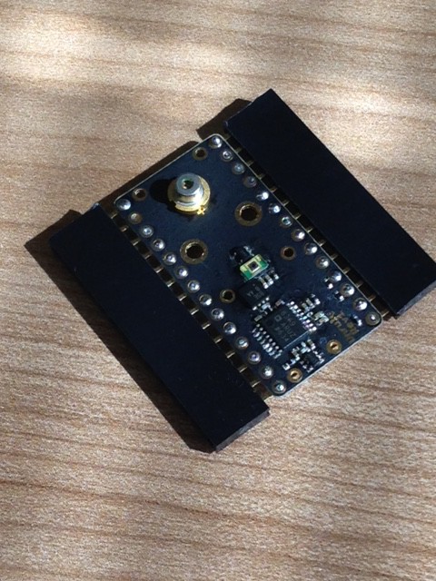
- The Unruly is a time-of-flight LiDAR that uses a pulsed laser diode (PLD) to generate a flash of light, an avalanche photodiode (APD) to detect the return signals and a high speed timer (TDC) to measure the return time.
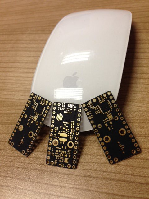
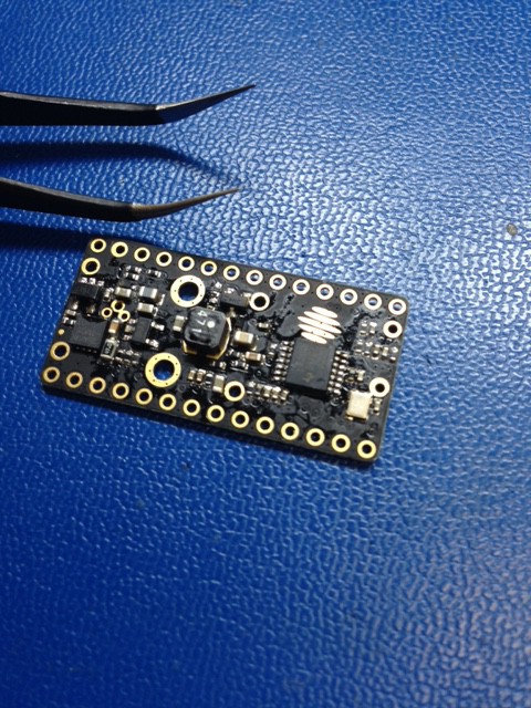
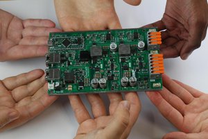
- The total circuit board area is one square inch.
- The measuring range can be adjusted to over 100m on natural surfaces and 250m on reflective surfaces, outdoors in bright sunlight.
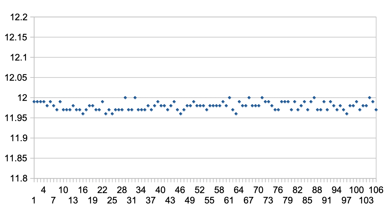
- The resolution can be configured down to 1 cm.
- The measuring rate is up to 1000 readings per second or maybe more ;).
- The laser power, pulse width and eye safety ratings are all under software control and can be set to Class 1, Class 1M or Class 3R to suit the application.
- The APD detector can be adjusted under software control to operate at optimum sensitivity taking into account temperature and ambient conditions.
- The amplifier gain can be adjusted under software control to achieve the best SNR (signal-to-noise ratio).
- The detection threshold can be adjusted under software control to set the false return error rate.
- Up to five different target returns can be measured on each laser shot.
- The total power consumption is less than 0.5 W.
- USB, serial and I2C communications are available at the same time.
- Two servo driver ports are available to control scanning (https://youtu.be/IirAJO5H0yI).
- A digital I/O for alarms or other purposes is available.
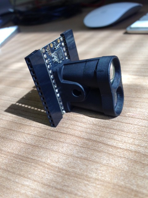
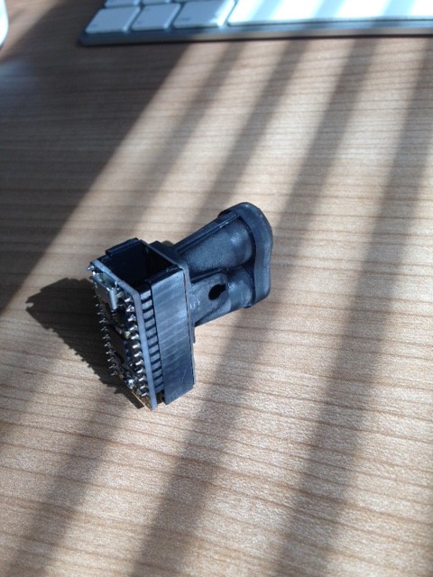
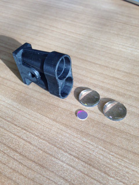
- Mechanical parts are 3D printable.
- EMC emissions are low enough for use with RTK and GPS systems without interference.
- EMC immunity is high enough to allow for use with BLE, WiFi, LoRa or other radios in close proximity (still to be tested).
The Unruly use of open source hardware: ItsyBitsy M4 Express
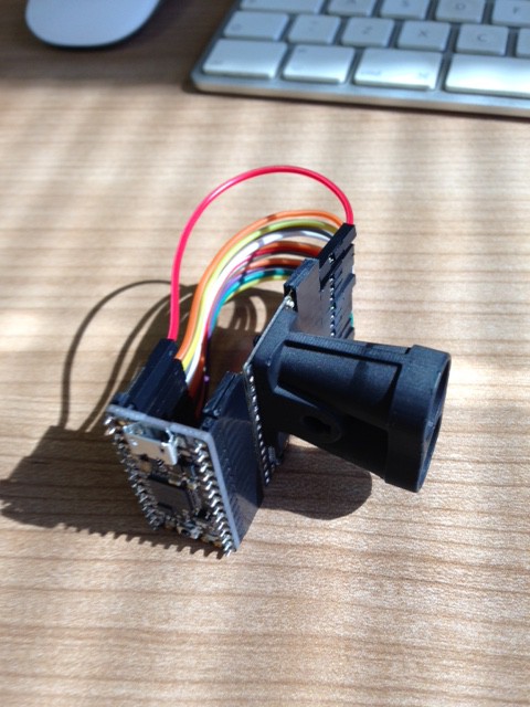
The Unruly uses existing open source hardware as a starting point, the Adafruit ItsyBitsy M4 Express. This is a small microcontroller board with a SAMD51 processor, extra flash memory and almost nothing else. Why, you are asking, have you chosen such a basic controller board to manage the complicated hardware of a LiDAR? Well, my wife likes how small it is and it has a cute name. Of course it helps that the SAMD51 runs at 120MHz and has a bunch of really interesting peripherals.

The Unruly use of open source software: CircuitPython
Another reason for choosing the ItsyBitsy M4 Express board is that it can run a version of the programming language Python called CircuitPython. This is by far the least likely language to be used in a high speed embedded system, especially one that needs to work at the speed of light. Python is an interpreted, high level language that manages variables and memory in a vague, non-specific way. There are only a few APIs and these do stuff that is no use to a LiDAR.
But CircuitPython is easy to write, easy to read and can be programmed without an IDE by using a basic text editor. This seems like a good enough reason to use it.

 Laser Developer

 FiftyOne
 Illinois Space Society AV
 Mastro Gippo
 Jean Alinei
Thank you very much for this project! It is very interesting.
Please, can you answer this questions:
- You write "The measuring rate is up to 1000 readings per second". What is the limiting factor?
- You write "Resolution confirmed <1cm for nearby targets indoors". Is it true for single measurement (without averaging)?
- APD S10341 is looking hard to find. Is it possible to use AD500-8?
- You write "The TIA has a differential output impedance of 150 ohms so its bandwidth can be controlled by a capacitor (C23)"
I think that amplifier for a TOF rangefinder must have maximum possible bandwidth. So what is the reason for decreasing bandwidth by this capacitor?
- Are you going to publish the oscillograms from different points of the device?