Laser Developer
-
Rev3 - Getting closer to production
02/22/2019 at 07:32 • 4 commentsDESIGN
- This revision will use the MAX3658 or MAX40658 TIA. The two different versions will be catered for on the PCB so that the manufacturer can chose the one with the best price.
- There will be no VGA post-amplification. This will reduce the measuring range a little but make the product much cheaper.
- The unit will be able to run on a 3.6V battery.
-
Rev2 - Unruly design for lower cost
02/02/2019 at 14:53 • 0 commentsDESIGN CHANGES
Once the design of a product is complete the hard work begins. The principle of operation and basic functionality remain the same but new constraints must be considered such as the availability and price of parts, ease of manufacture, tooling for lower costs and so on. These constraints make the difference between an idea and a product that can be made and sold. Hence the Unruly Rev2 has:
- New amplifier chain chipset - lower price but similar performance.
- Started adding test points for production.
- Get quotes for tooling optical carrier component.
- Get commitment from a manufacturer.
- Get commitment from a distributer or two.
----------------------------------------
TESTS
The boards have arrived and test results are as follows:
1. The first test is to evaluate the performance of a new LiDAR specific TIA from Analog/Linear called LTC6560.
Positives: In terms of sensitivity, noise characteristics, overdrive recovery and stability this is a great component. It provides enough gain that there is no need for a post amplification stage thereby saving on component costs. It operates right at the theoretical limits of performance, meaning that you are not likely to be able to design a better TIA circuit yourself.
Negatives: This device may have limited application in battery powered LiDARs because it needs a +5V power supply. It is also draws more power than the Maxim equivalents. To get full speed operation it needs a pull down resistor on the output which draws additional power.
----------------------------------------
CONCLUSIONS
On balance, I have decided not to use the LTC6560 TIA. I think that the requirement of running on a 5V supply will make battery powered operation painful. Everything else runs perfectly on a 3.6V battery so it doesn't make sense to lose that capability.
On the matter of production, LightWare has offered to produce the Unruly provided that we can get the retail price below US$100. Using the MAX4658 TIA is the cheapest option so this fits well with this requirement.
Additionally, we can remove the VGA post amplifier to reduce the price further. This will bring the useful measuring range down to about 60m but for most robotics applications this is more than enough. The maximum range is still beyond 100m but it needs a large white wall as a target.
So, on to Unruly Rev3!
-
Rev1 - Final test article
01/20/2019 at 16:33 • 7 commentsRev1 is a stable test board for further software development. New features specifically for educational purposes have been added:
- Laser pulse width controls added.
- Laser power controls added.
- Updated laser CAD model to improve optical alignment.
- Made I2C pins available to the user.
- Increased mounting holes size for optical parts.
- Moved main supply to HVI to allow for battery operation.
- Added power controls on VGA through D2 PWM.

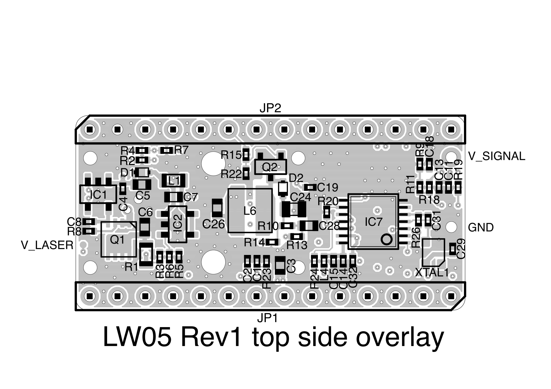
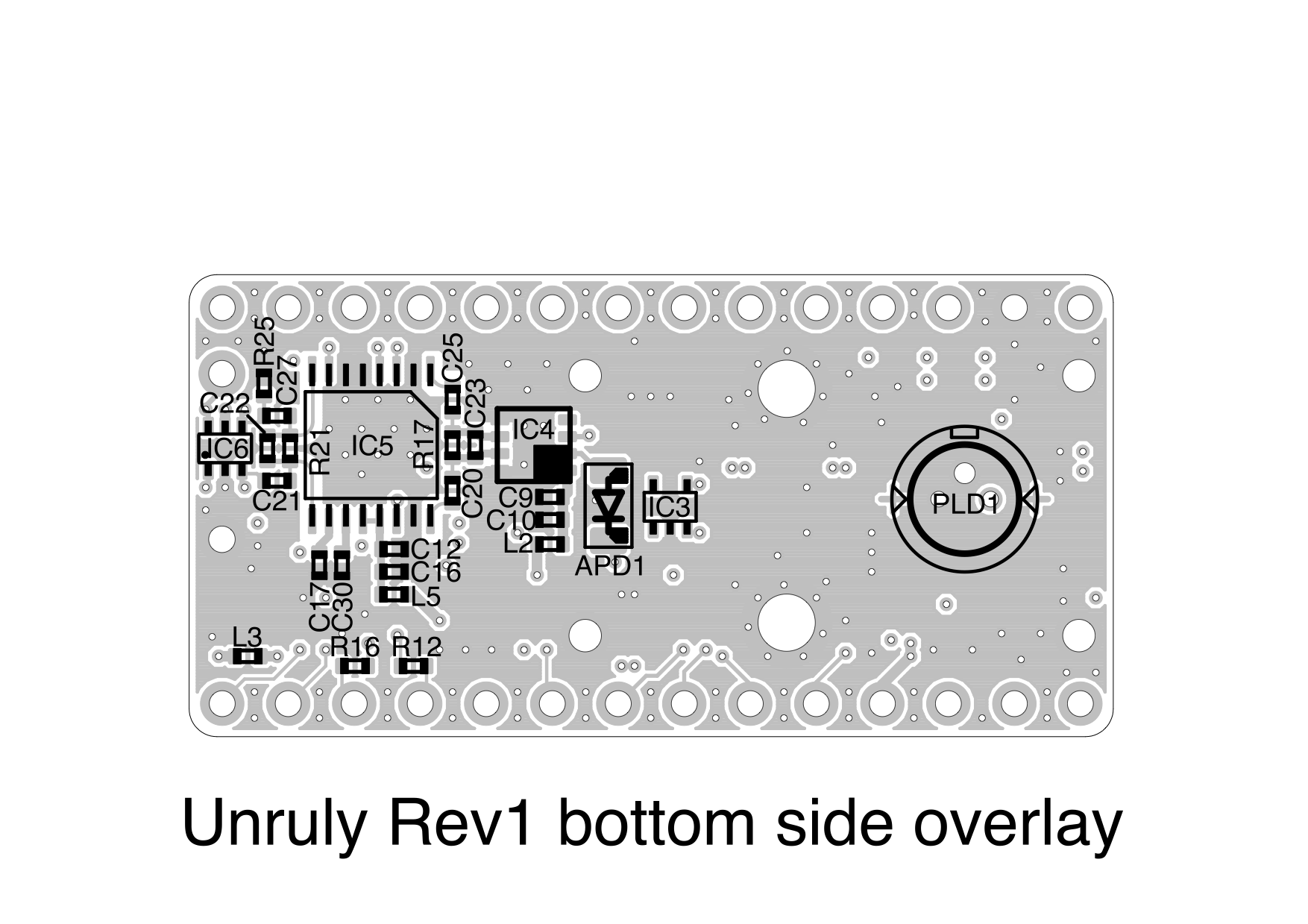
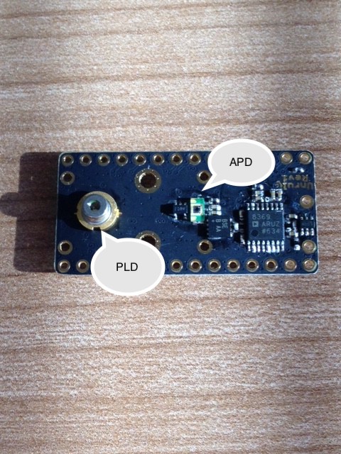
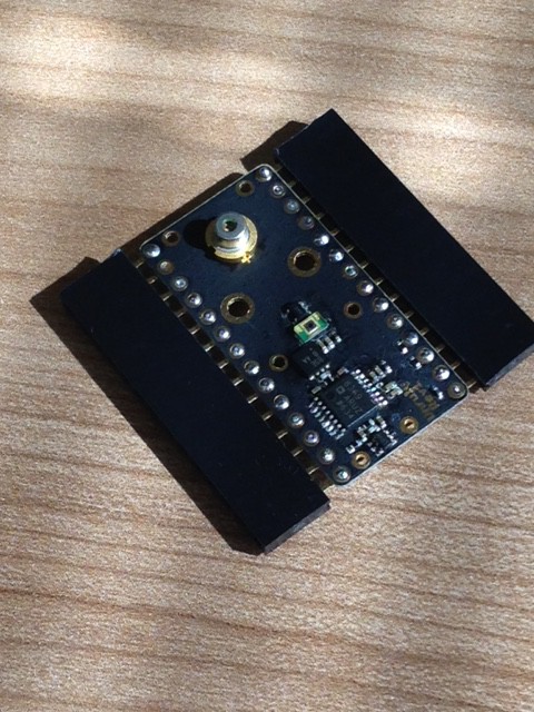
You will notice on the circuit board overlays that there are lots of small holes and very few visible tracks. The holes bridge the inner ground layers and outside layers together to reduce transmitted interference and cross talk between the laser driver and receiver circuits. The signal tracks are on the inner layers, shielded by ground plains, to reduce electromagnetic susceptibility.
Above is the top side of the board and below is the other side showing the pulsed laser diode (PLD) and the avalanche photodiode (APD). At the moment we're using a laser from Laser Components and an APD from Hamamatsu.
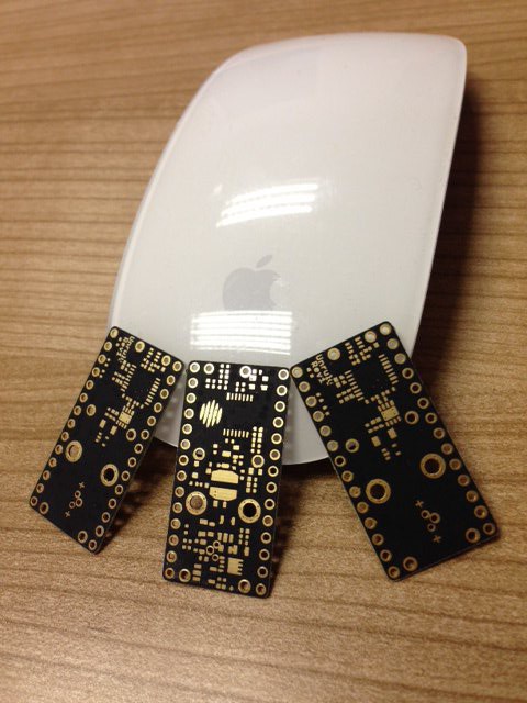
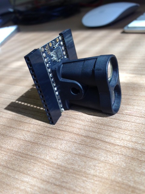
In order to test Unruly it's important to be able to access the components on both sides of the board while it is running. This is done by adding "wings" instead of headers. These wings are just headers soldered on at right angles.
The optics are then screwed on.
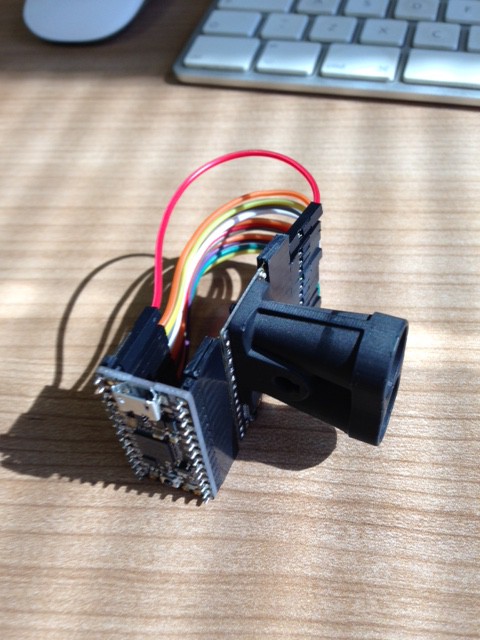
Using the wings, jumper cables connect the ItsyBitsy M4 Express to the Unruly LiDAR leaving the back of the circuit board accessible to an oscilloscope.
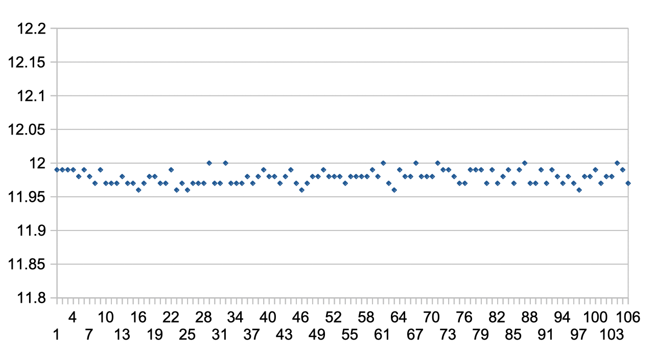
Test 1 - Unfiltered signal stability - indoors:
Results:
Single shot STDEV (standard deviation) = 1.0 cm (33 ps)
Single reading APD bias voltage measurement STDEV = 0.11 V
Single reading APD temperature measurement STDEV = 0.2 C
-
Rev0 - Initial test article
01/20/2019 at 16:24 • 0 commentsThe following tests were conducted on Rev0:
- CircuitPython APIs tested. Note that import order is important for correct hardware configuration and pin assignments.
- Range confirmed >100m on grass and tress, >250m on reflector.
- Resolution confirmed <1cm for nearby targets indoors.
- Update rate set to 1024 readings per second to allow for interleaved software functions.
- EMC - emission levels extremely low especially around 2.4GHz and all satellite bands.
- EMC - susceptibility minimal over wide range of frequencies and power levels.
- Power consumption - VGA draws significant current (48mA) so power control added to Rev1.
- With VGA power control on the average consumption is approximately 70mA at 5V.
- Operation on battery connection confirmed.
- Serial port tested (not I2C).
- Servo ports tested. Note that port D4 produces 3.3V logic but port D5 produces 5V logic.
- Initial eye safety testing done. Repeat for Rev1 to include the laser power controls.
- Confirmed laser SMPS draws 2.5mA at firing rate of 2048 shots per second.
- Confirmed APD high voltage supply draws 2.0mA at operating point.
- Lenses and optical filter characterized through functional testing.
Open Source LiDAR - Unruly
We've been waiting a long time for someone to post the plans of a working LiDAR. Is it really going to happen?