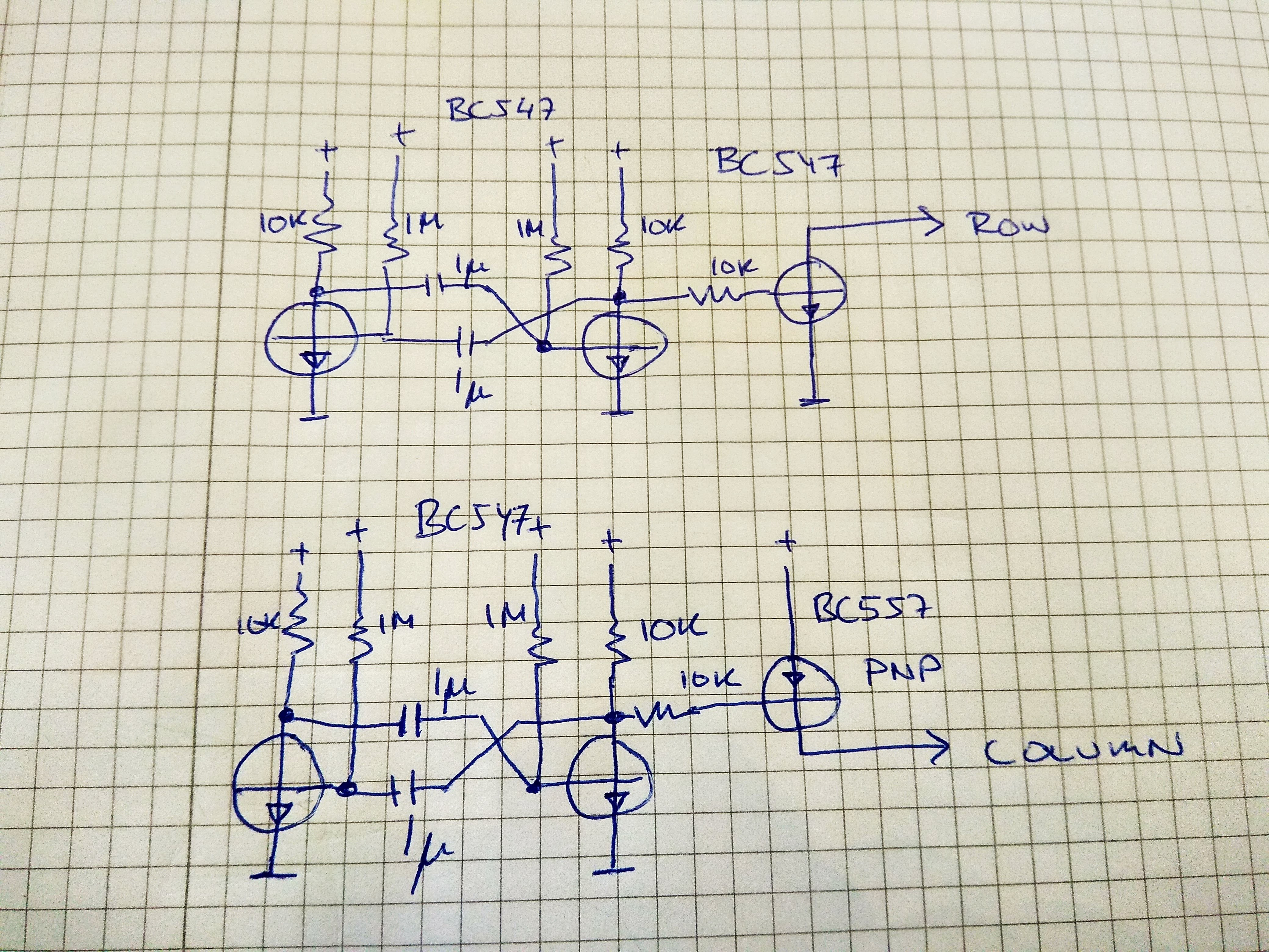
Since the LEDs are in a matrix I need to have the oscillators both push VCC into columns and also connect GND to the rows. So I need two different types of modules for that
The oscillators themselves are just the bog-standard two-transistor, four resistors and two caps thingie. And to be able to push and pull current I added a NPN driver transistor to eight of them, and a PNP driver to the remaining eight.
Using 1uF caps and 1M for the timing resistors I ot about 0.7Hz when running at 5 volts, slightly slower at 3 volts.

Eight of each of the two types of oscillators are needed for the 8x8 matrix.

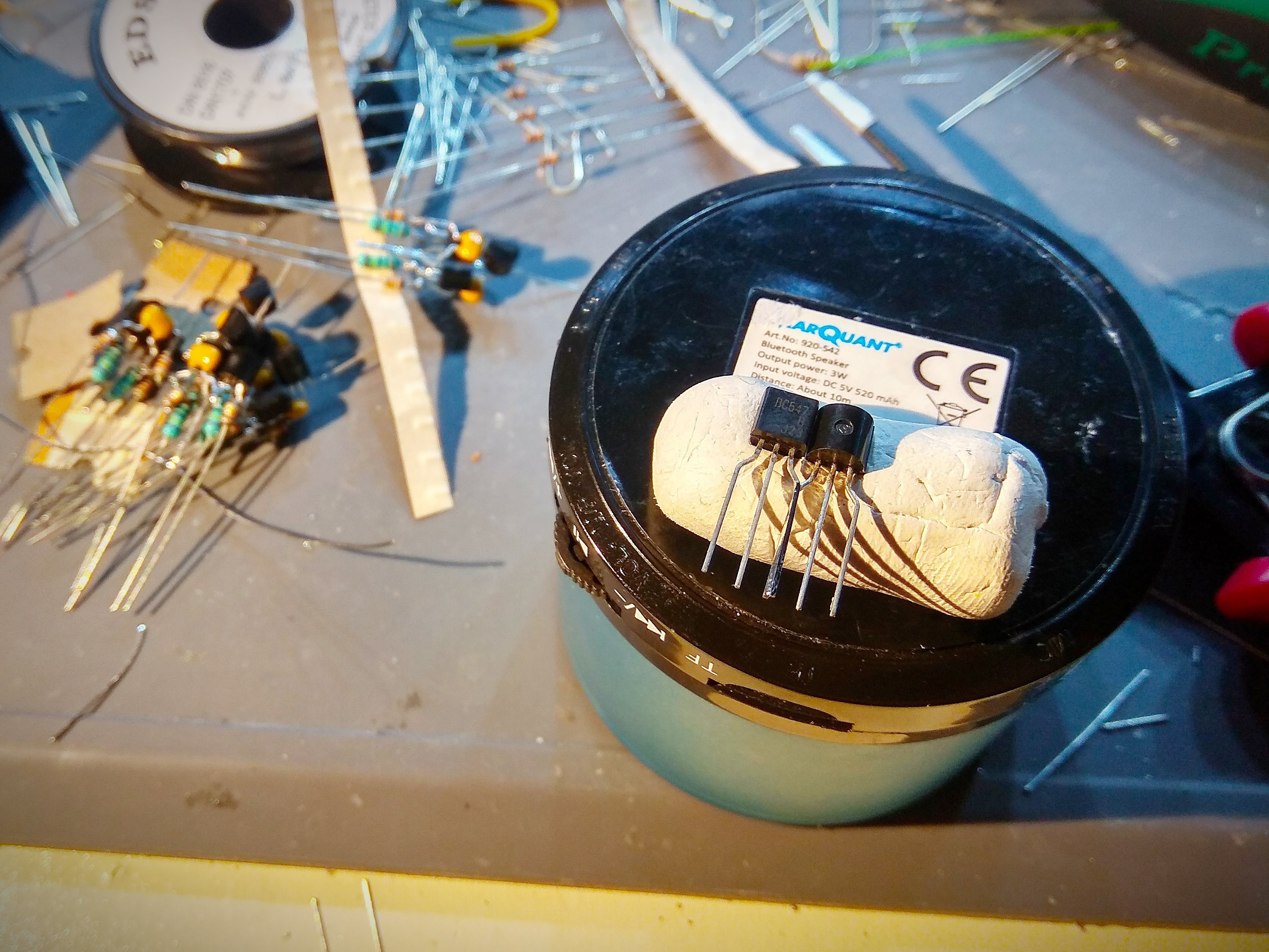
I re-discovered the usefulness of using blu-tack to hold parts while soldering - but even using that it took quite a while to freeform 16 oscillators with 9 parts each.

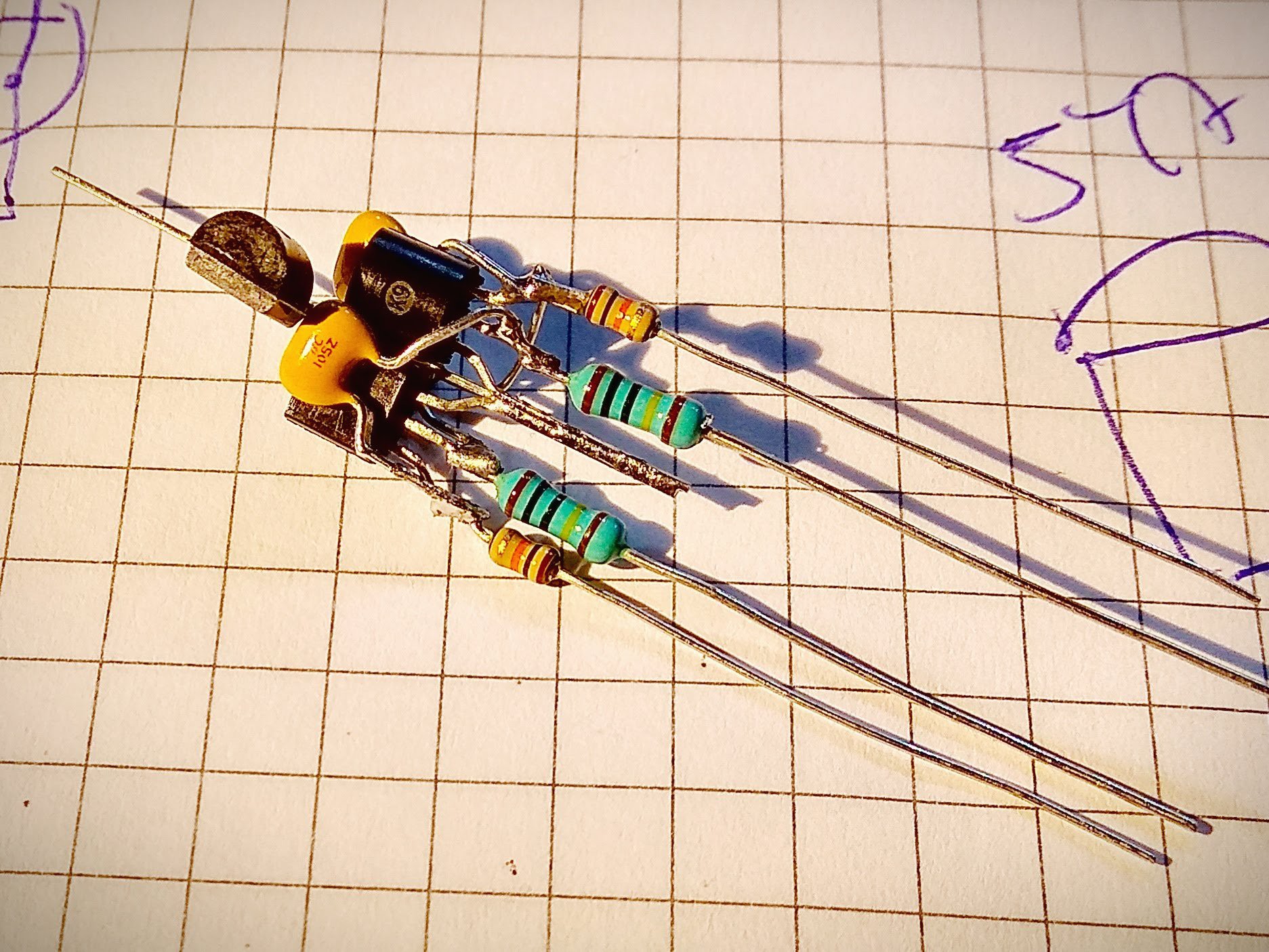
This is one of the NPN-driver oscillators that pulls a row to ground when active. The PNP oscillators looks more or less the same except for the top transistor that is in a slightly different position to access VCC instead of GND.
 matseng
Discussions
Become a Hackaday.io Member
Create an account to leave a comment. Already have an account? Log In.