Arduino Enigma
-
First Electrical Tests With All Panels Connected
03/09/2019 at 17:08 • 0 commentsSoldering this was a lot of fun. So now it is time to start putting it together.
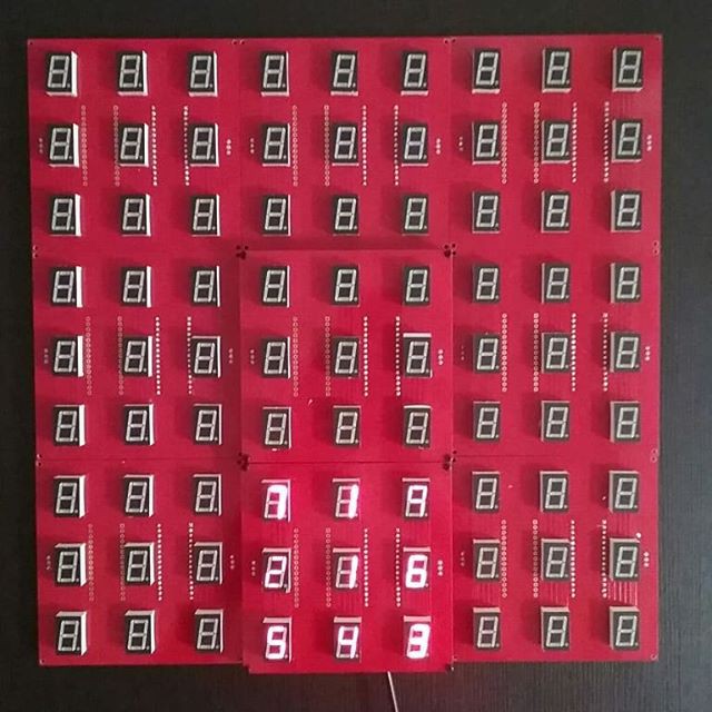
This is how it will look.
![]()
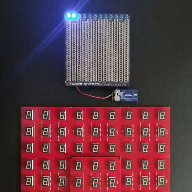
Comparison with Motivational Board, another monster soldering project. Care to guess which one has more solder joints, the Motivational Board or the Seven Segment Art Installation?
![]()
Powering up all the tiles in a daisy-chain configuration by feeding 6V DC to the first tile. Each tile is running a standalone animation. This eats a pack of AAA batteries quite fast. It will be run from a 6V or 9V wall adapter. Each Nano is responsible for converting raw DC power to 5V.
An Arduino Nano on a separate breadboard is sending data to the first tile in the installation. The data gets relayed to the last board. Shown below is a demo of double buffering. The data gets written to a buffer that is not visible and then a command is sent to swap the visible buffer with the other one.
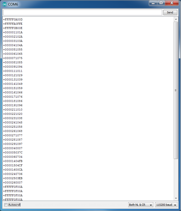
Below are the commands the Master Arduino sends to the first tile. The first 5 characters are a board address, FFFFF means this command is meant for all the tiles. Each tile processes it and re-sends to the tile down the chain.
The first command selects buffer A, the visible one, for all future commands. The second command lights up all the segments. The third command selects buffer B for all future commands. Then boards 0, 1 and 2 are initialized, but not displayed. Finally, a flip command is sent every few seconds to all boards to swap the A and B buffers.
![]()
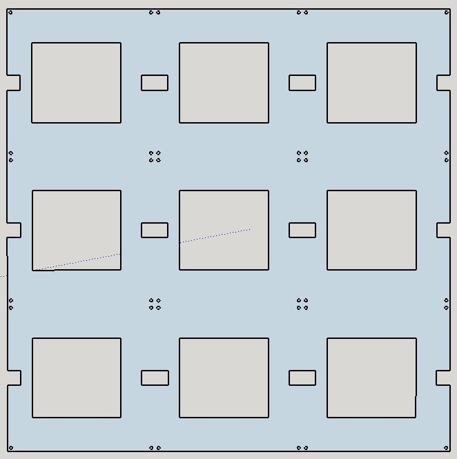
Next step is to design an acrylic piece to mount all the boards. This will get laser cut at Ponoko. The design below is missing 4 mounting holes in the corners to bolt it to a larger piece.
![]()
-
Ordering some parts
03/06/2019 at 00:49 • 0 commentsJust ordered some components from US suppliers, so they should get here fast:
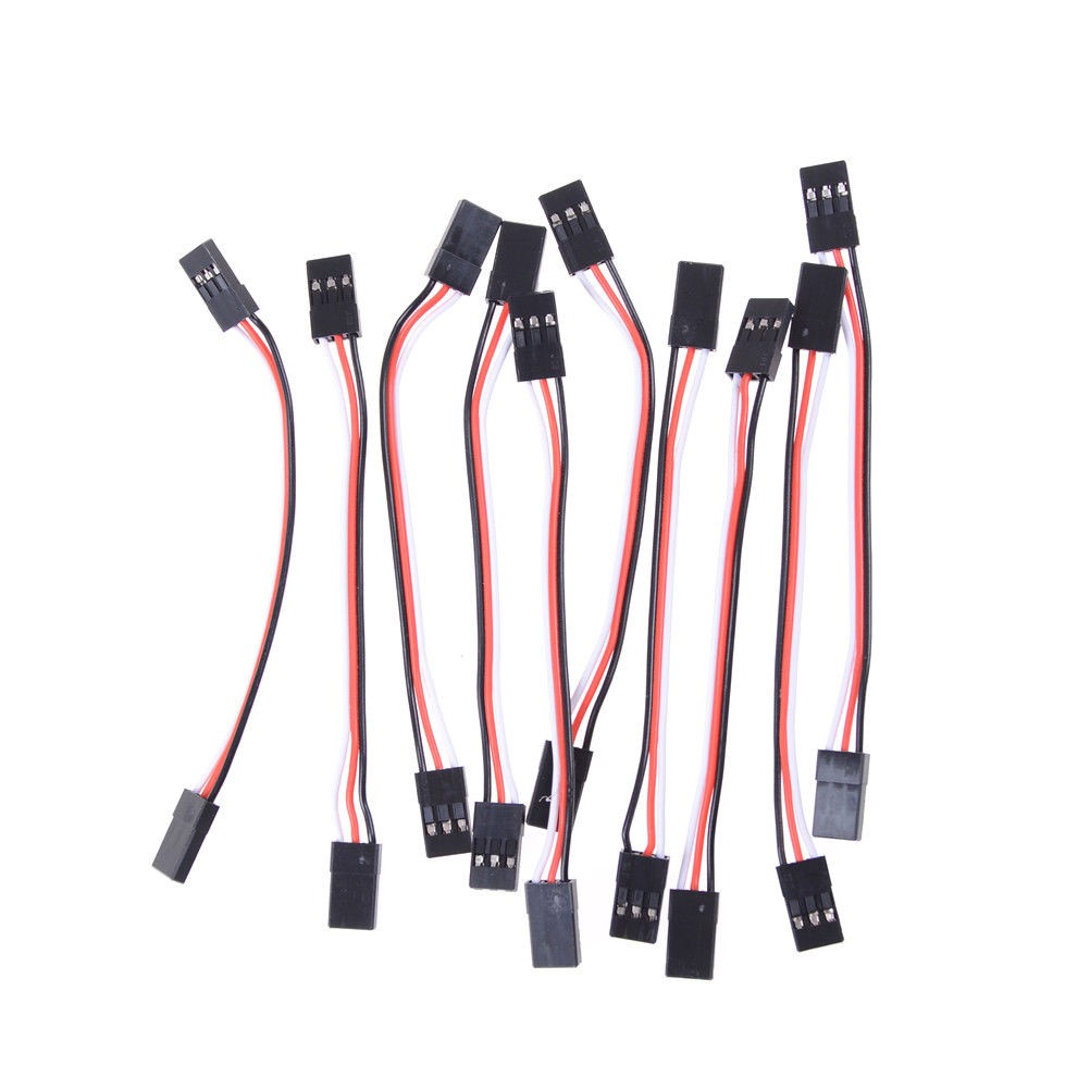
10 x 3Pin 10cm Servo Extension Lead Wire for Futaba RC Connector Cable LB
![]()
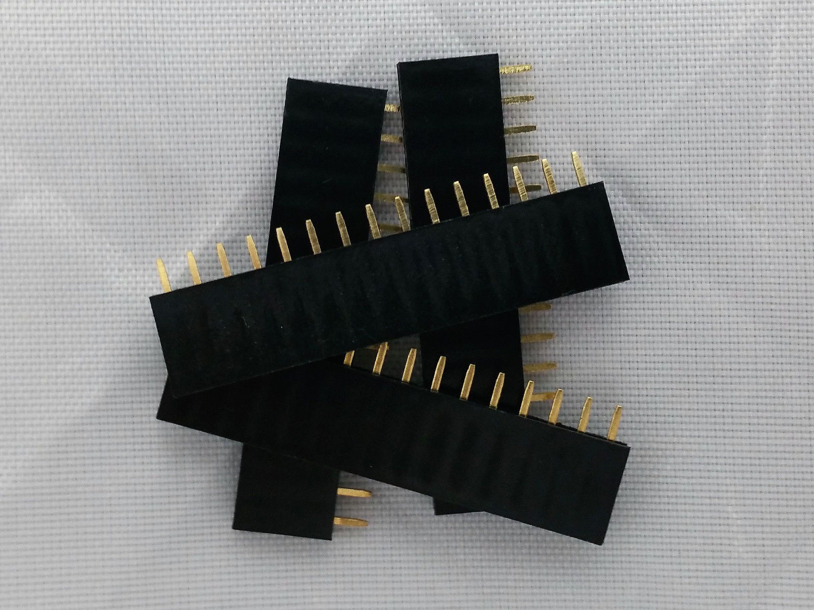
10Pcs 2.54mm Pitch 0.1 1x15 15 Pin 15p Female Dupont Header Arduino Nano Headers
![]()
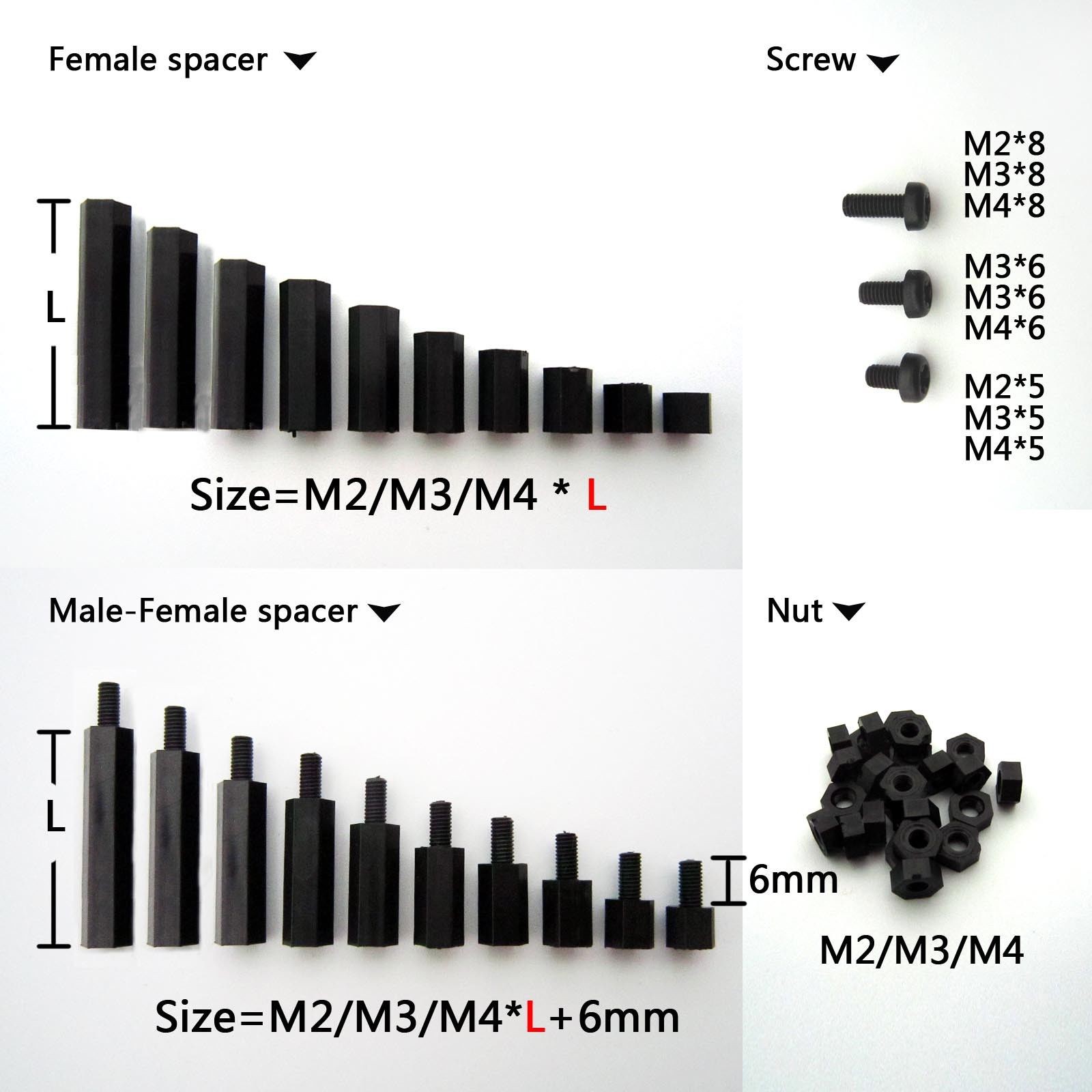
And then when those two arrive and everything is put together, then the spacers can be selected:
25/100pcs Black Plastic Nylon M2 M3 M4 Hex Column Standoff Spacer Phillips Screw
![]()
-
Everything is working, just a quick update...
03/04/2019 at 05:19 • 0 commentsEverything is working, so this is a quick update to list the location of all the resources to duplicate this project:
Here is the page to have the boards made at PCBWay:
The seven segment displays are:
Here is the code that runs on the Master Arduino. Its job is to send the desired content to be displayed down the line:
https://gitlab.com/arduinoenigma/seven-segment-art-installation/tree/master/Board100x9x13-Master
This is the code for the tile boards. It receives commands, processes and relays them down the line to other boards while continuously multiplexing the displays:
https://gitlab.com/arduinoenigma/seven-segment-art-installation/tree/master/Board100x9x13
-
A Little Preview
02/27/2019 at 11:46 • 0 comments -
Digit Animation Working
02/20/2019 at 04:42 • 0 commentsHere is the latest fade in effect. I am using a Sinclair calculator as a stand in until the seven segment displays arrive.
-
Tile Software Works!
02/03/2019 at 05:58 • 0 commentsThe tile software is now working on a Sinclair Calculator.
Since there are no current limiting resistors on the board, the software is being developed on a calculator. Once it is debugged and the displays arrive, it will be uploaded to a production board.
https://gitlab.com/arduinoenigma/seven-segment-art-installation/tree/master/Board100x9x13https://www.pcbway.com/project/shareproject/A_Seven_Segment_Art_Installation__tile_board_.html
-
The Inspiration For This Project
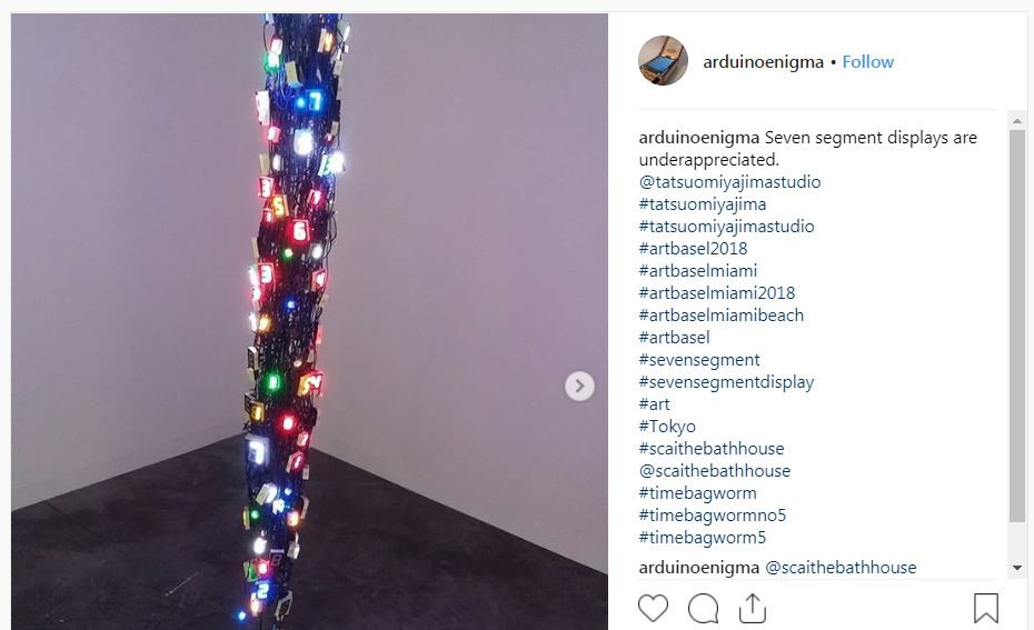
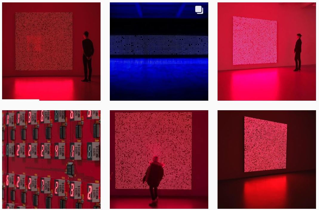
01/23/2019 at 05:35 • 0 commentsAt Art Basel Miami Beach 2018, I saw an art installation that consisted of seven-segment displays hanging from the ceiling. Some of the displays changed.
https://www.instagram.com/p/BrLMl_IHYBo/
![]()
The artist name is Tatsuo Miyajima, some of his art installations can be seen below. He specializes in using seven-segment displays.
https://www.instagram.com/explore/tags/tatsuomiyajima/
![]()
This got me thinking. An Arduino Nano can drive 9-10 Seven-Segment Displays in a multiplexed arrangement. Up to 11 displays can be driven if one does not connect the decimal point.
A board size of 100x100mm can comfortably fit 9 0.56" (13mm wide) displays and an Arduino Nano to control them.
The boards will be networked using two 3-pin headers. The header carries power, ground and a serial port signal. The header on the left connects the serial port to the receive (RX) pin on the Arduino Nano, and its TX pin is connected to the header on the right. This way, each Arduino in the chain receives commands from an upstream device and sends them to the next device.
The first board will have two Arduinos soldered, the first one holds the instructions to light up the digits in the whole installation and it sends serial commands to the other Nano in the same board, this Arduino will light up the LEDs and forward the rest of the commands down the line to the other boards.
This project is designed for manufacturing, the board size is selected to take advantage of price specials, Only three components are used, an Arduino Nano, seven-segment displays and a three-pin header. All of the components are through hole. The only other components needed are jumper cables to connect the boards, standoffs, a piece of wood or plexiglass to mount the boards, and a power connector.
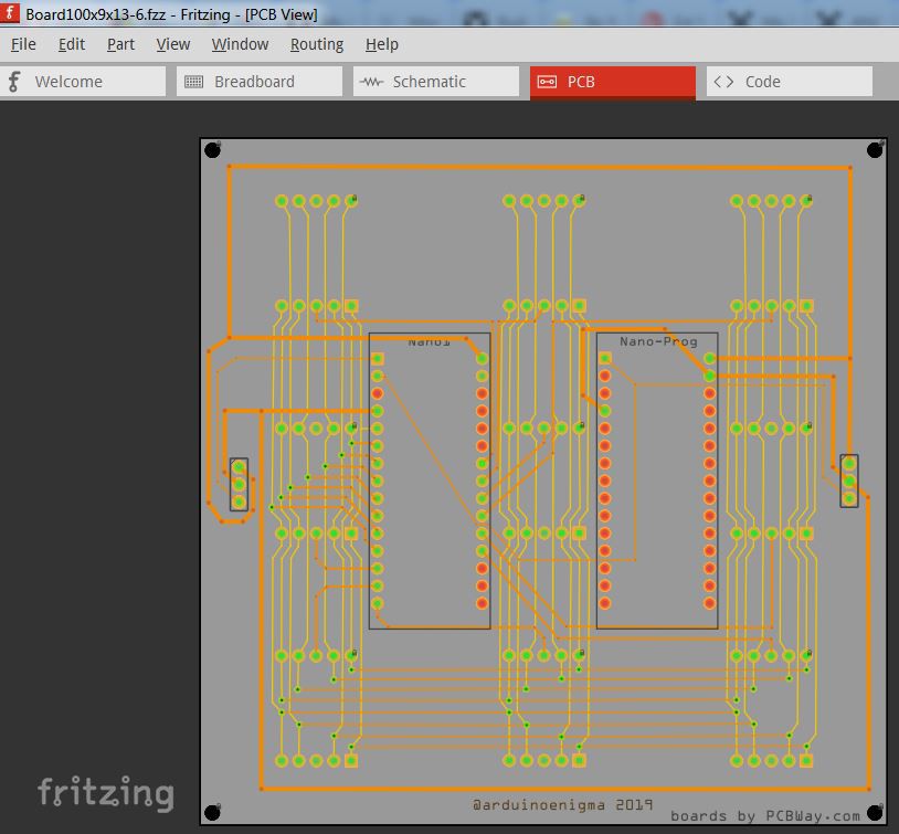
A board was quickly designed in Fritzing. The front layer has a minimal amount of vertical lines, the rest of the traces are in the back. All of the vias are hidden under the displays.
![]()
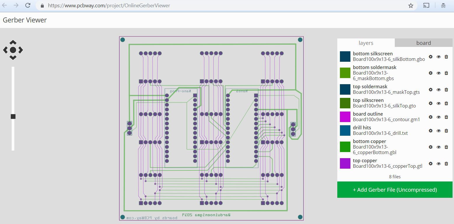
The board gerbers were exported and uploaded to PCBWay Gerber viewer.
https://www.pcbway.com/project/OnlineGerberViewer![]()
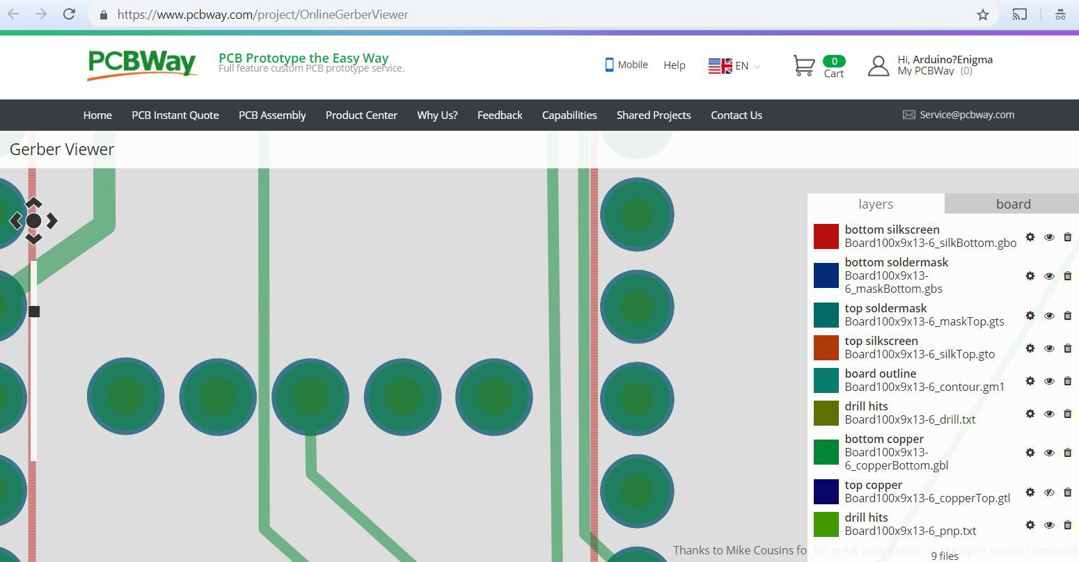
I really like the new version of the tool, the board can be zoomed in to identify problem areas. PCB layers can be turned on and off and it renders the board in the production colors.
![]()
The board will be manufactured in Red, to match the color of the seven-segment displays linked below:
The front side of the board is very minimalist, no marks whatsoever, vias hidden under the displays and a minimum of copper showing. The design is symmetric.
![]()
The back has a few markings and a little more copper visible.
![]()
Parts have been ordered. Stay tuned for part two...
You can also follow this project on Instagram:
https://www.instagram.com/arduinoenigma/
A Seven Segment Art Installation
A modular board hosting 9 seven-segment displays that can be daisy chained to make an art installation