Arduino Enigma
-
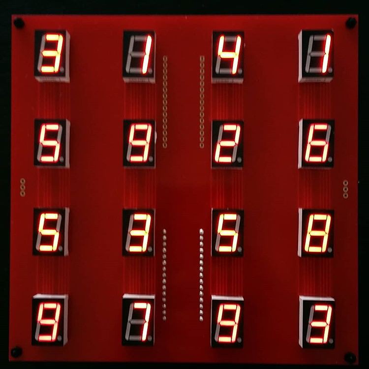
The tile board can now control 16 digits using only an Arduino Nano
08/16/2020 at 17:36 • 0 commentsHere is a picture of the new 16 digit board using the Common Anode (CA) in parallel with Common Cathode (CC) technique.
![]()
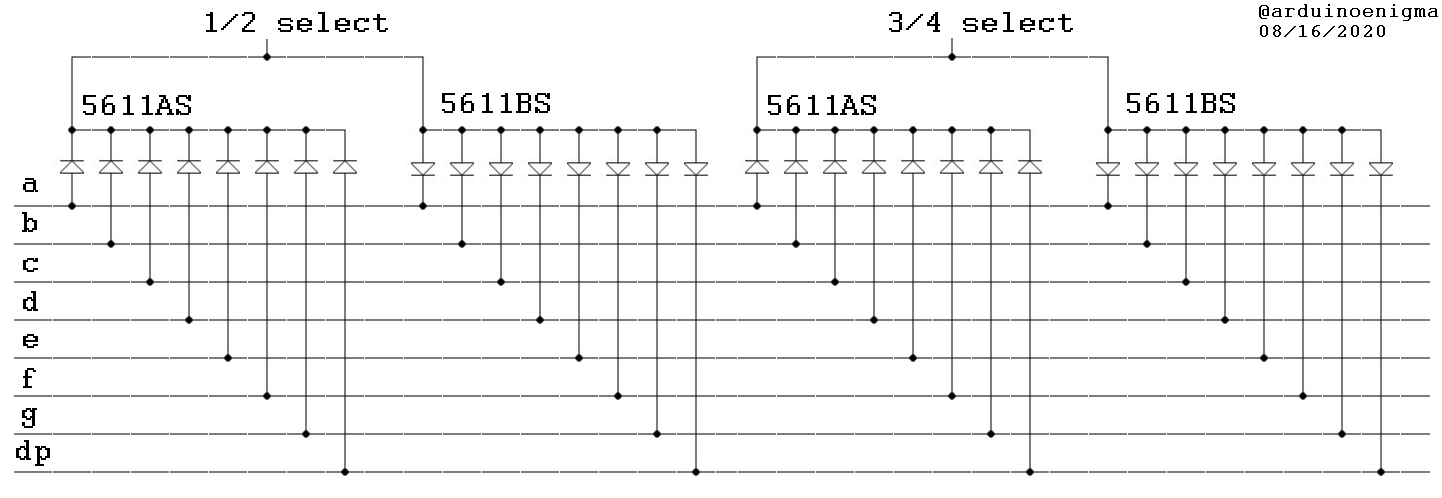
Here is a schematic for a 4 digit board using only 10 IO pins. Each additional pair of digits will only cost 1 pin.
![]()
Read more about it at:
https://arduinoenigma.blogspot.com/2020/08/7-segment-led-board-now-drives-16-leds.html
-
More Digits!!!
05/19/2019 at 13:44 • 0 commentsI have found a way to add more digits to this installation. The key is to put a common anode seven segment display in parallel with each common cathode existing display. The capacity is instantly doubled to 18 or 20 digits maximum.
Now:
-8 pins on the Arduino connect to the segment pins on the seven segment display.
-9 select lines connect each of the common pins back to the Arduino.
Future:
-On the 8 pins used for the segments, connect 9 common anode displays and 9 common cathode displays.
-each of the select lines goes to the common anode of one display and the common cathode of another display.
To illuminate one digit, put the pattern on the segment lines, using 1 for the segments that will illuminate, then put 0 on the selection line for a pair of digits. Then put another pattern using 0 for the segments that will illuminate and put 1 on the selection line for that pair of digits. Lastly, put the selection line in input (high impedance) and move to the next pair of digits.
Using this technique a tile can go from 9 digits to 18. To keep the square form factor, lets do 4x4, using 8 common anode and 8 common cathode displays.
Parts have been ordered to test this technique...
-
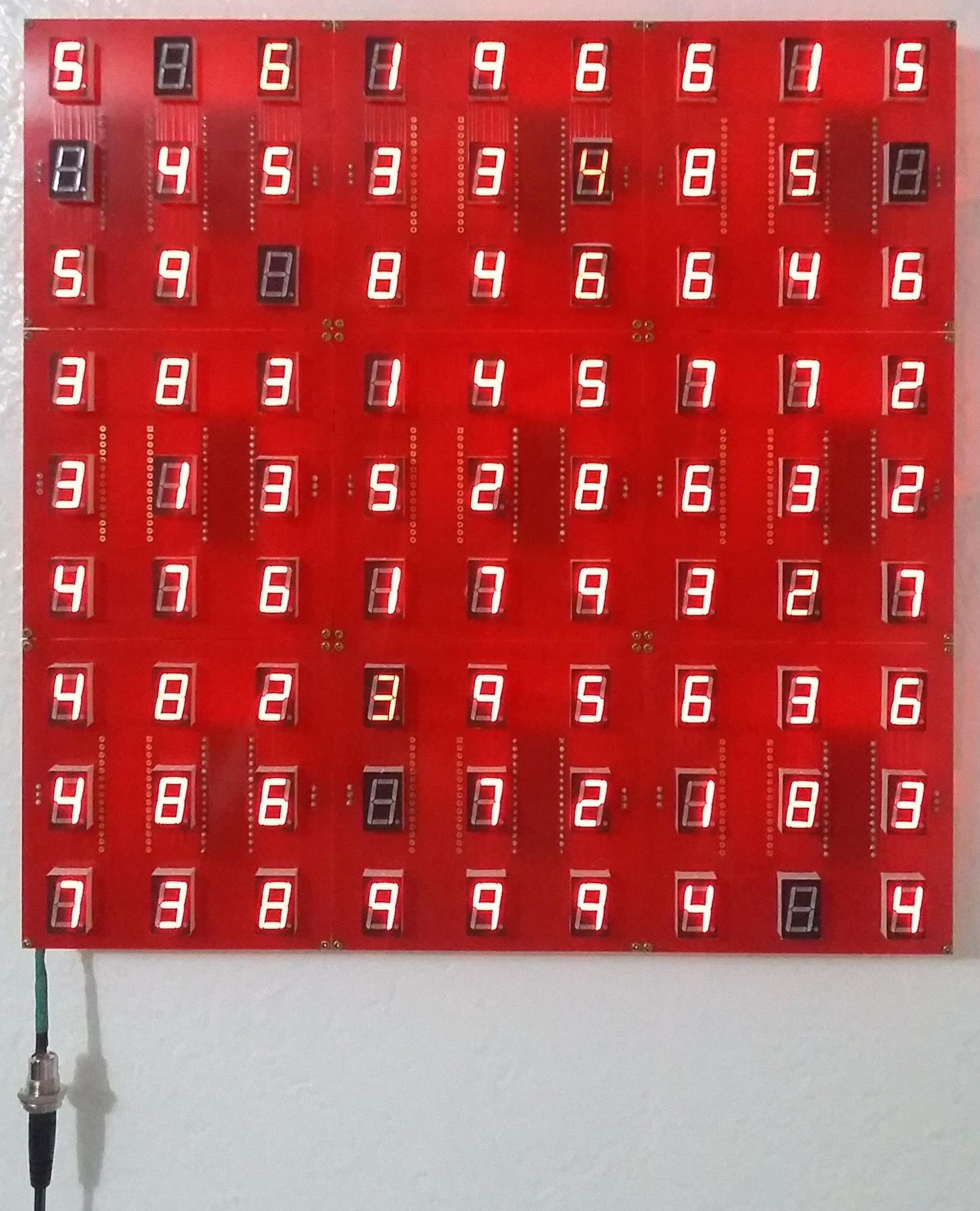
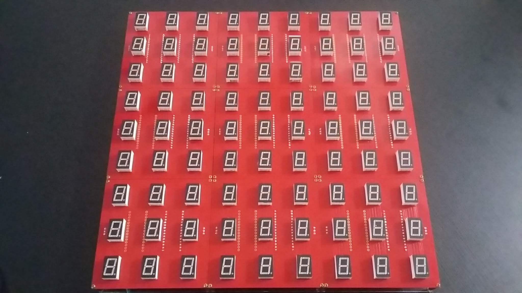
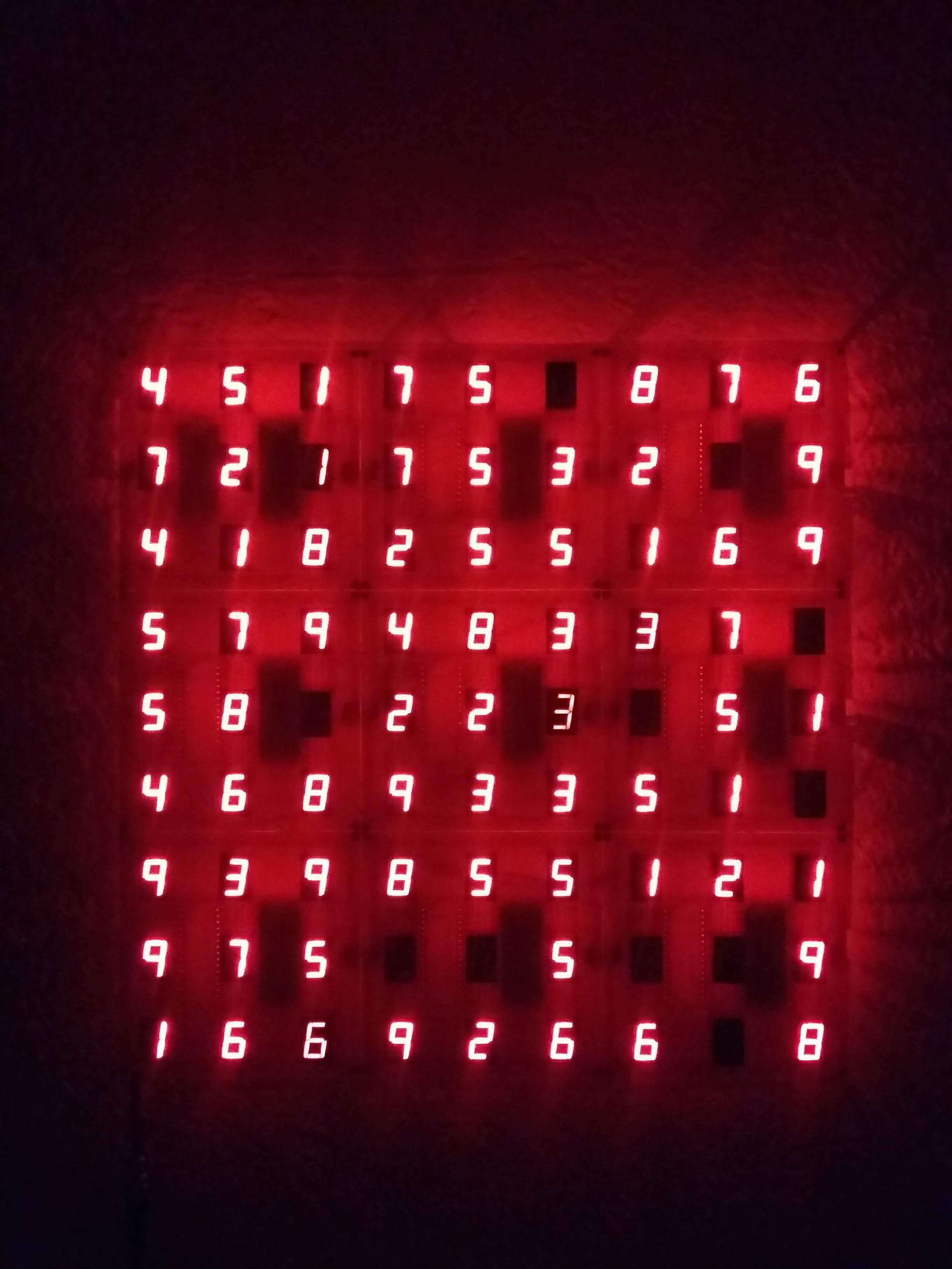
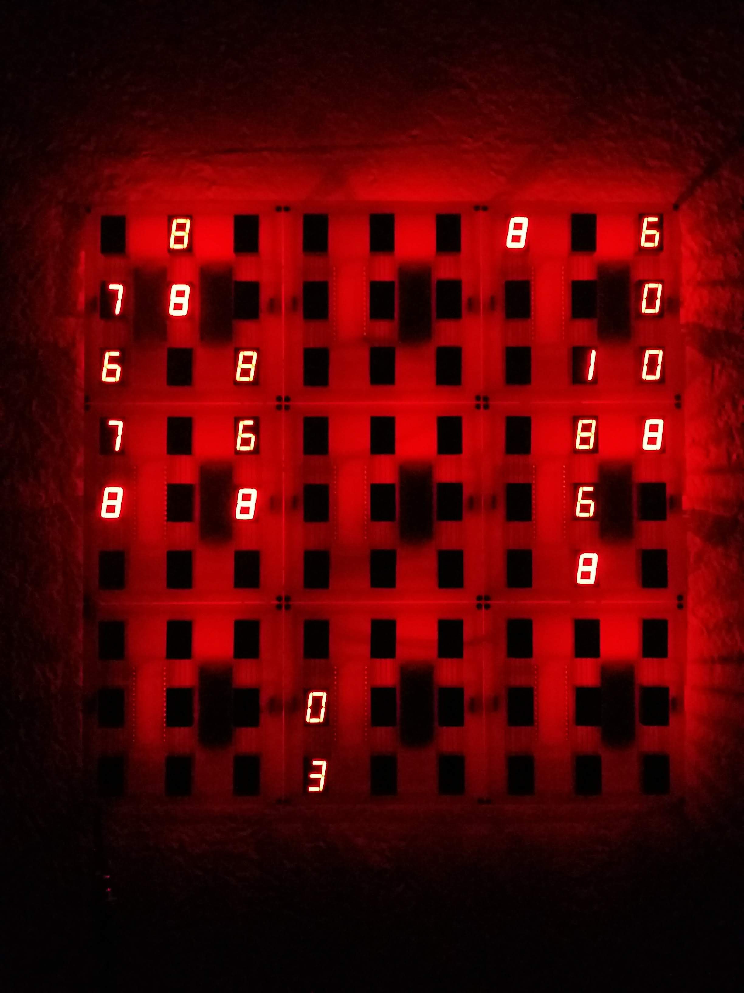
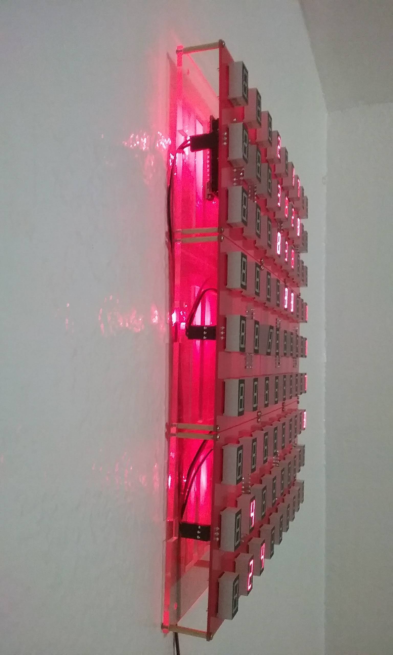
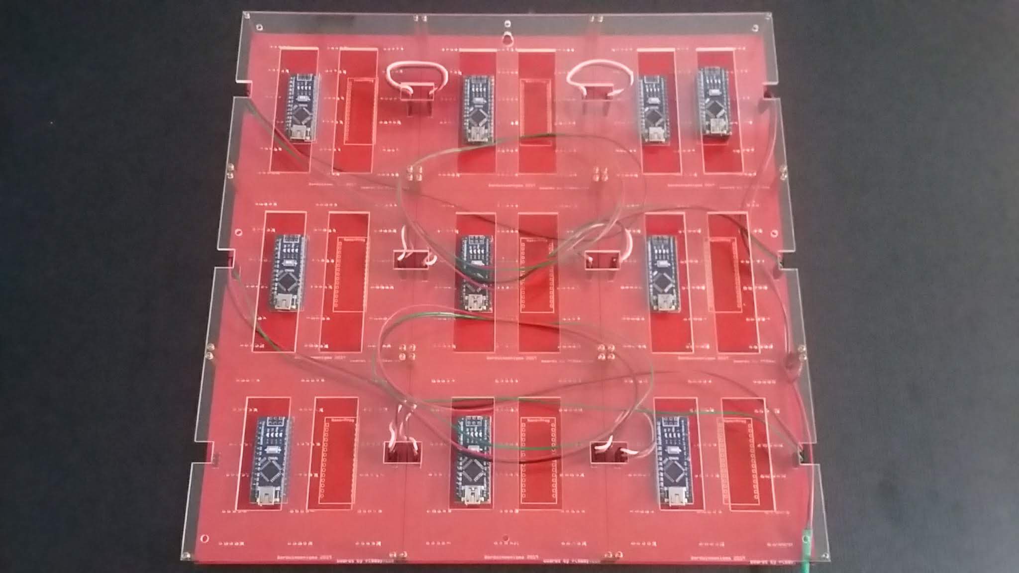
Pictures of the front and back of the assembled object
04/29/2019 at 04:30 • 0 comments1
![]()
2
![]()
3
![]()
4
![]()
5
![]()
6
![]()
7
![]()
8
![]()
9
![]()
-
Display Fully Assembled - Falling Digits Animation
04/10/2019 at 04:30 • 0 commentsAll the parts finally arrived and the display can be put together.
Here it is running a falling digits animation:
and the original animation that inspired this project:
And a pseudo-random number generator using a Fibonacci Linear Feedback Shift Register:
-
A small design while waiting for spacers to be delivered
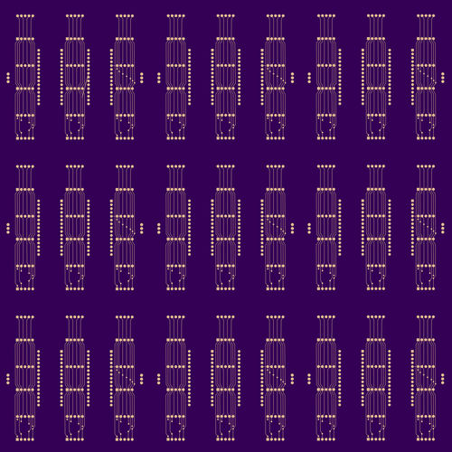
03/31/2019 at 03:11 • 4 commentsWhile waiting for delivery of the spacers to mount the boards to the back plate, I put together this design to stress test Fritzing. Copy and Paste takes a while, DRC fails with a success message, but it did not crash, until the silkscreen label on the back copper was moved up and down using the keyboard.
@Benchoff, ready for that little contest...
![]()
-
![]()
-
![]()
-
![]()
-
Who wants to see this made?
![]()
-
-
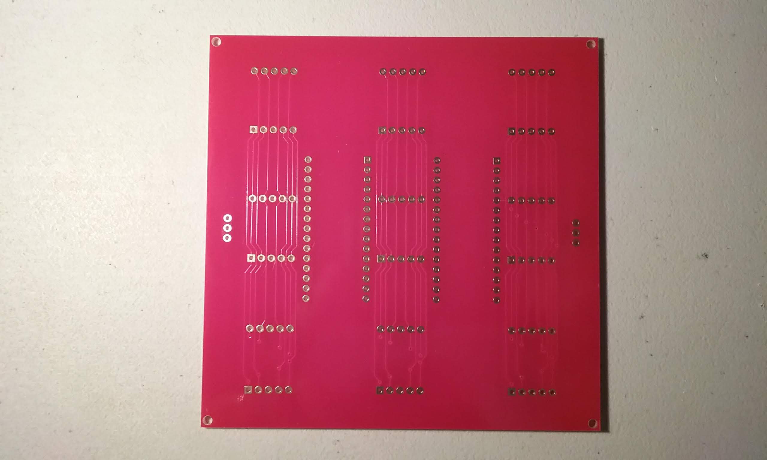
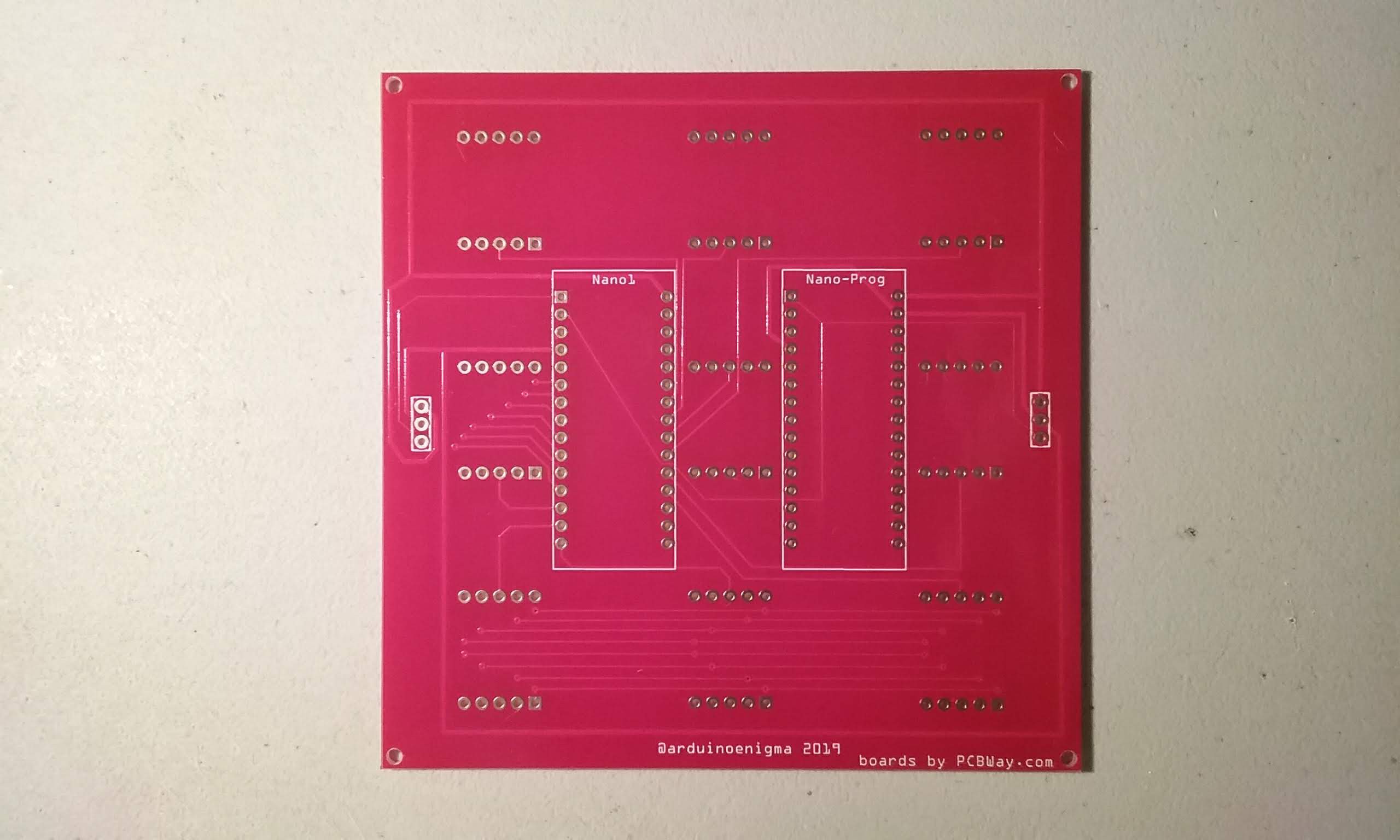
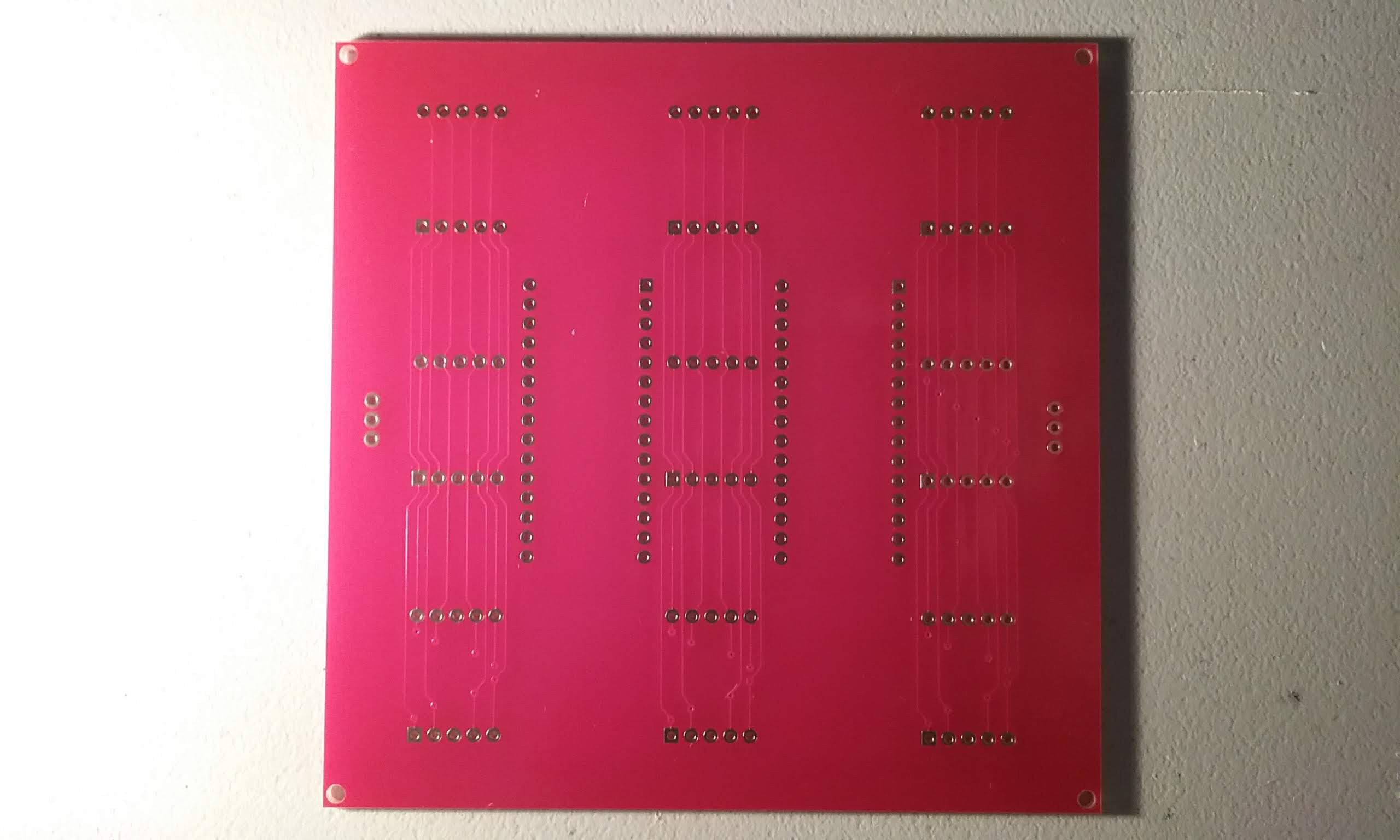
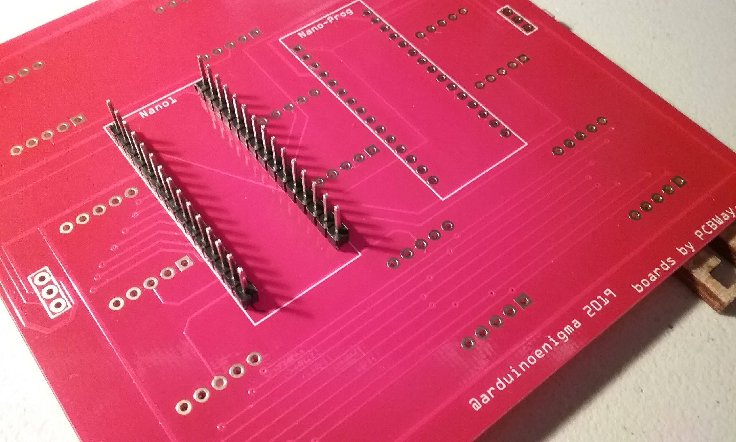
Illustrated Assembly Guide
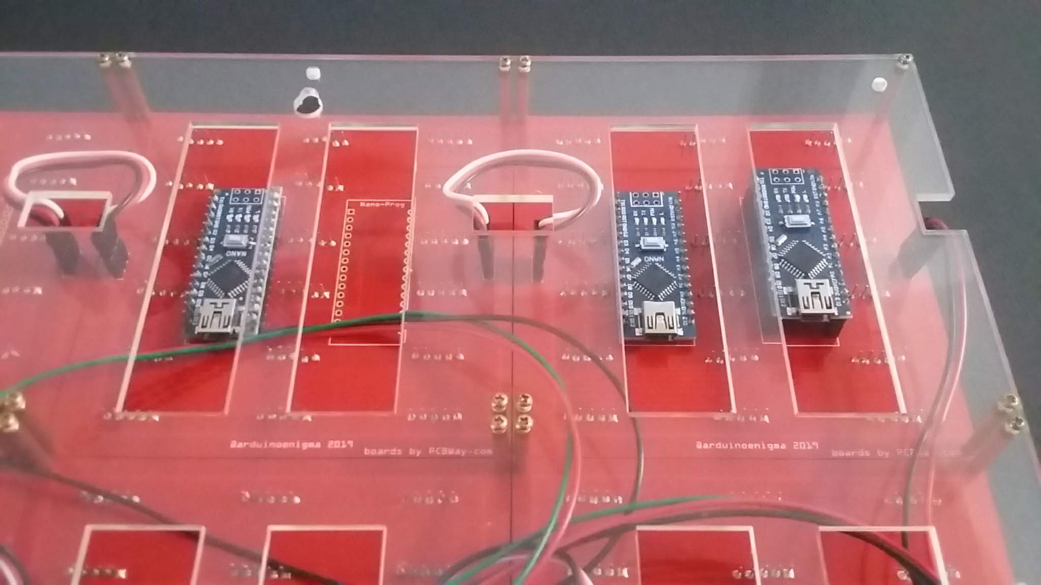
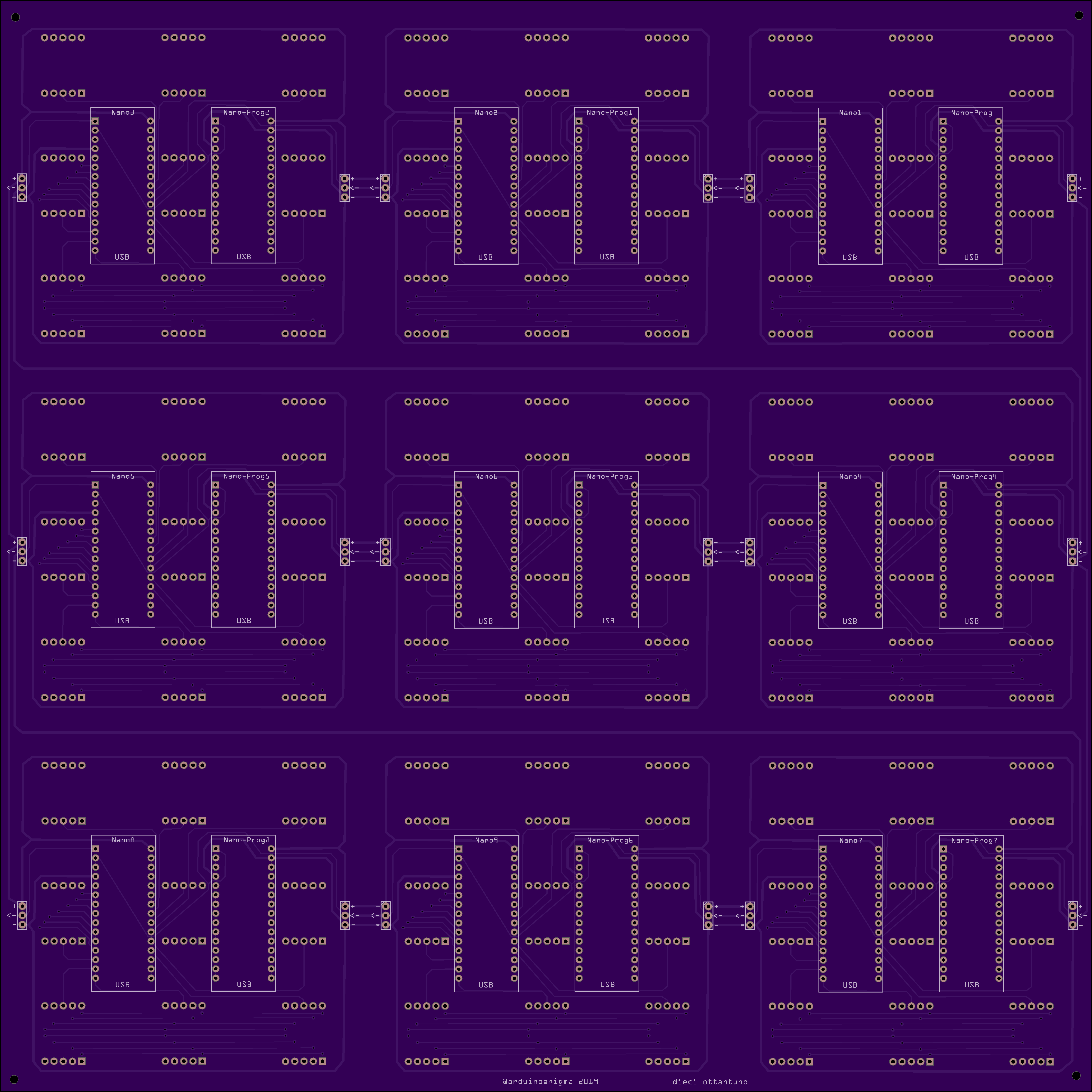
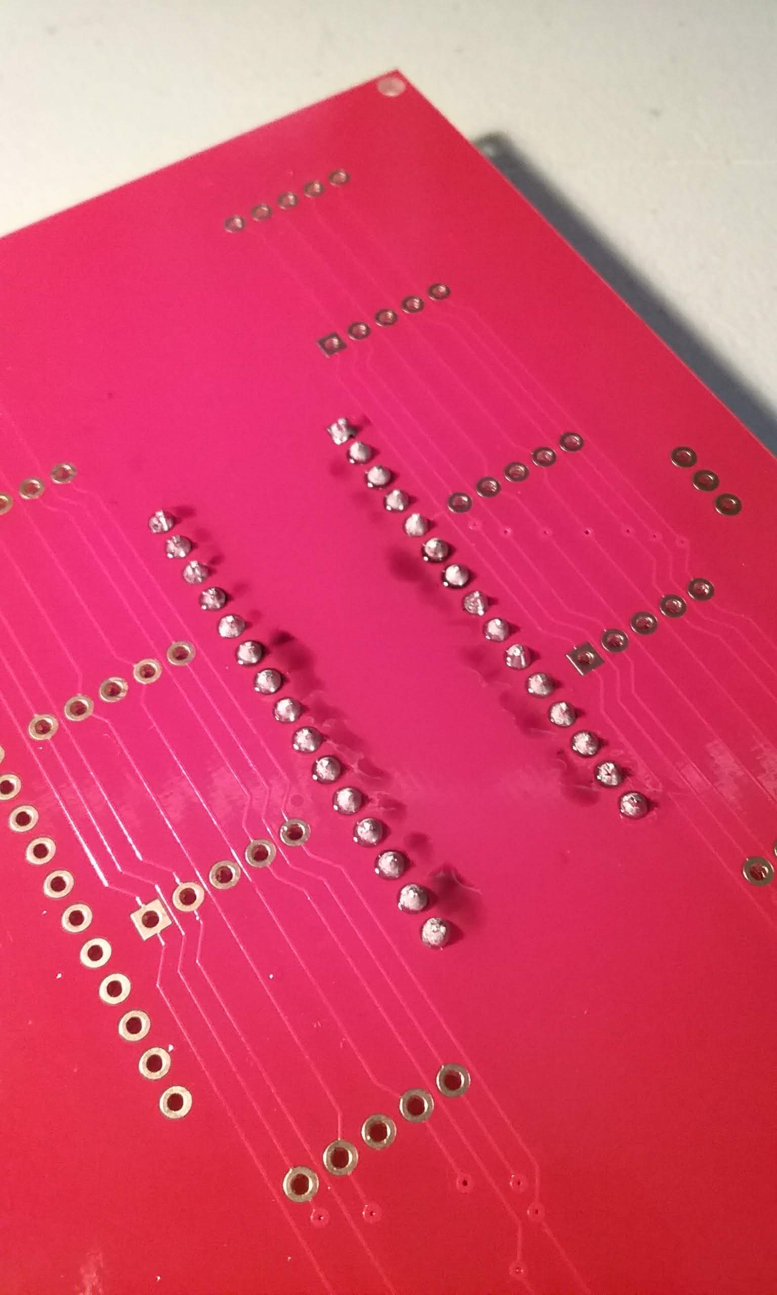
03/18/2019 at 00:18 • 0 commentsThe following pictures show the assembly process for a one Arduino Nano slave tile. Shown also are the steps that need to be taken once to make a master tile with two Arduino Nanos.
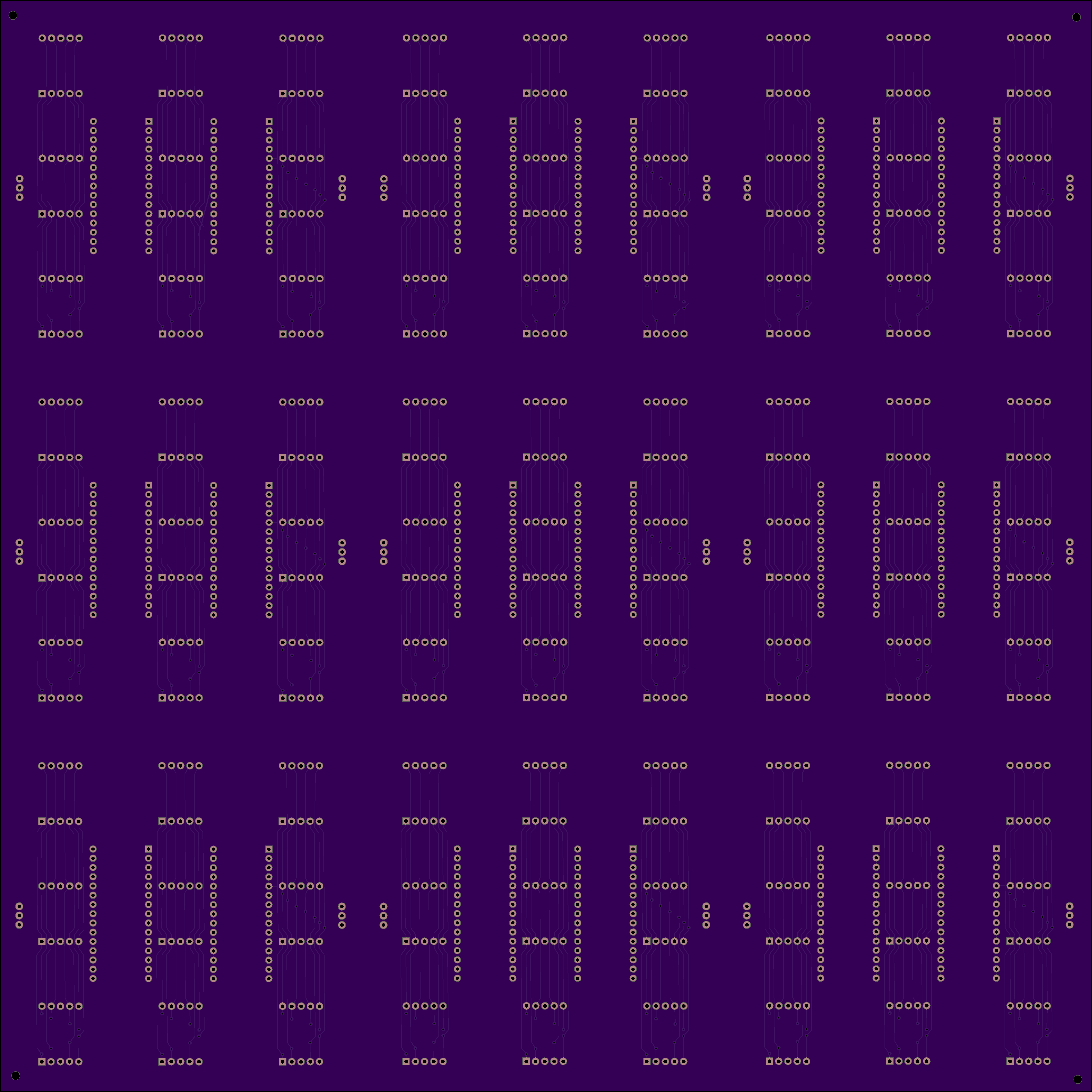
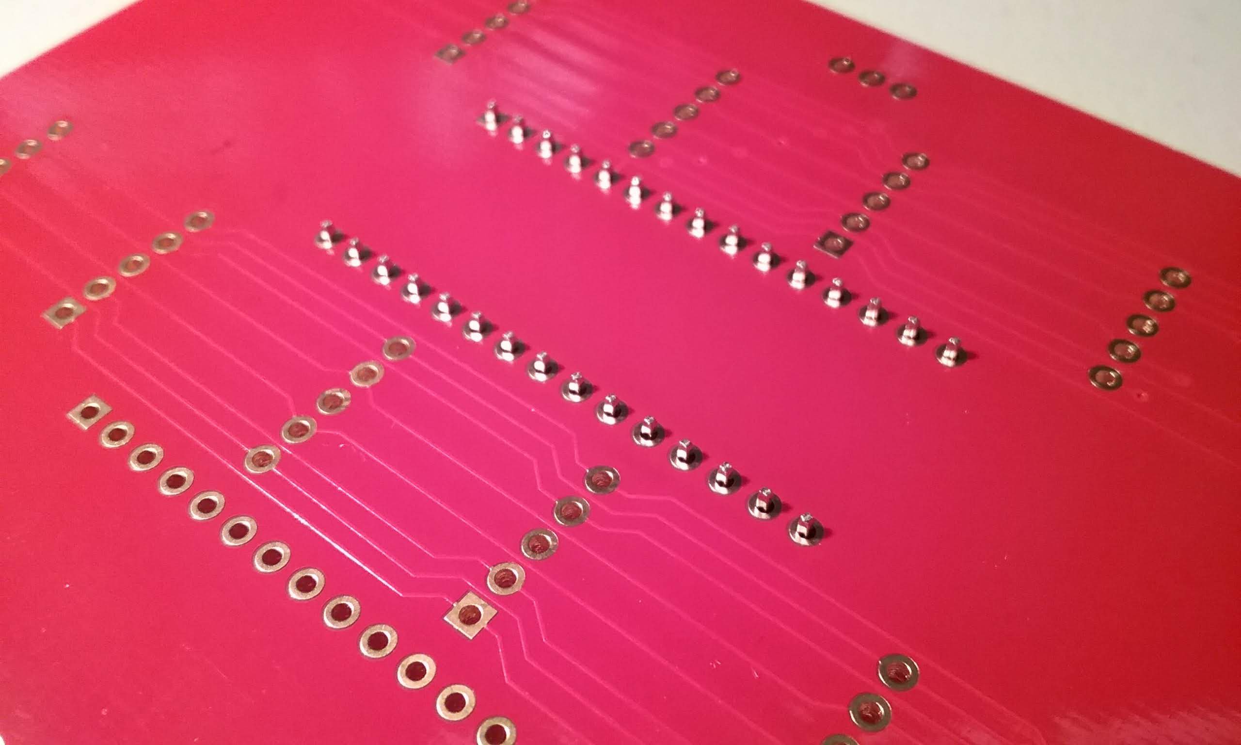
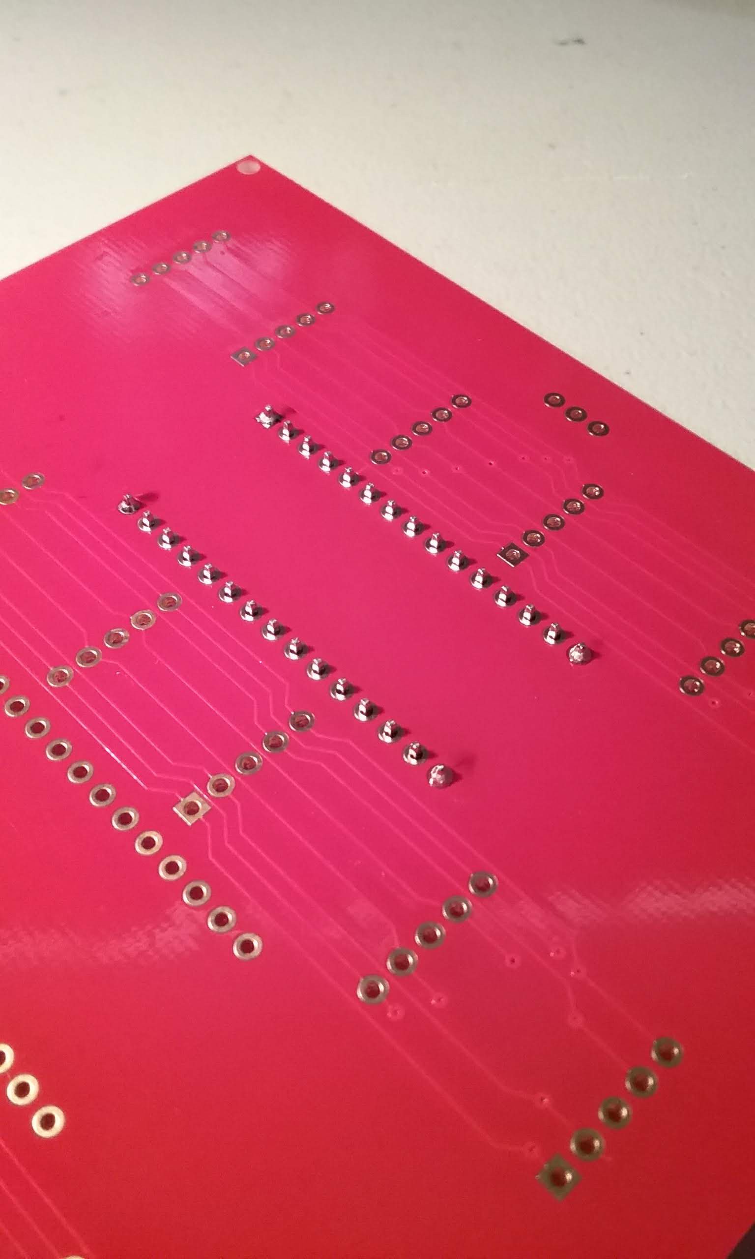
It all starts with ordering this board. Some work went into making sure the front was clean of marks, the only clue that this is oriented the right way is that the vias on the lower part. Those vias will be hidden under the displays when this is assembled.
In order to keep the front of the board clean, it is important to put on the order a note: "do not add order number to board" PCBWay has been good about doing this.
![]()
Here is a shot of the back. It has a few silkscreen markings, but those will almost disappear once assembled.
![]()
Trying to show the traces in the front. The red soldermask is really, really shiny and hides the tracks...
![]()
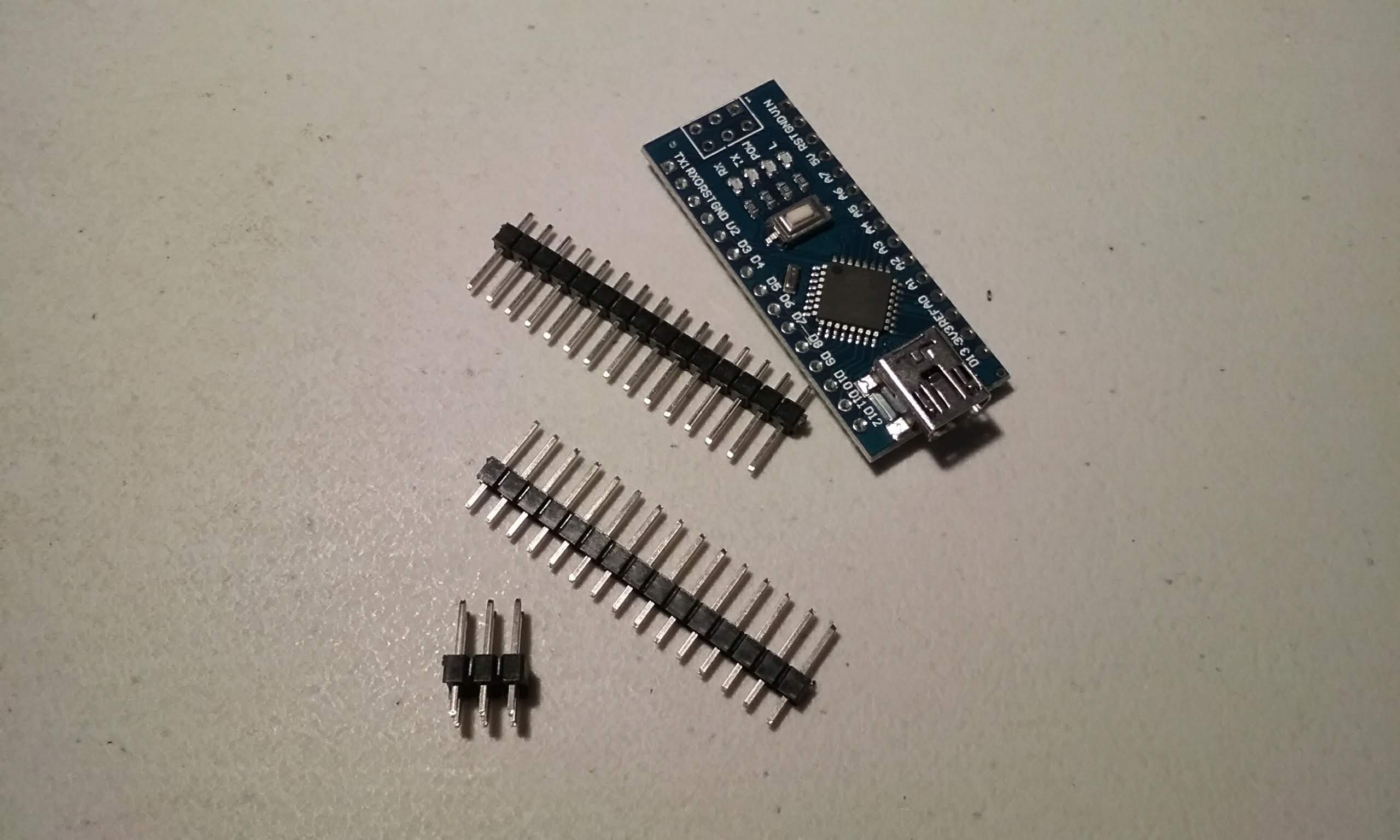
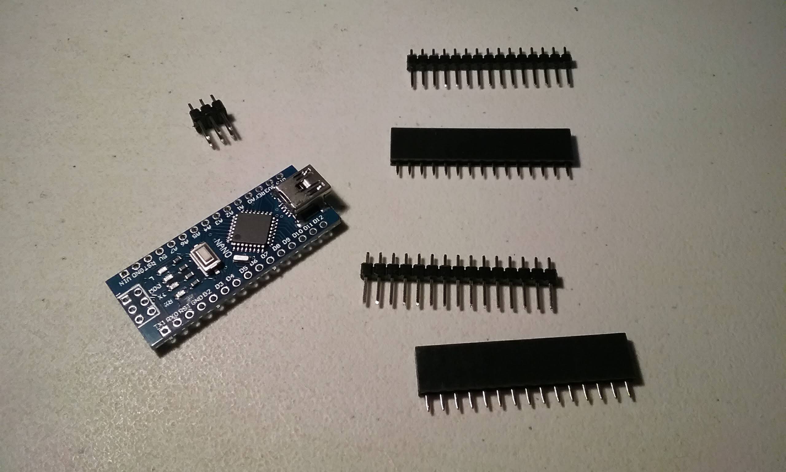
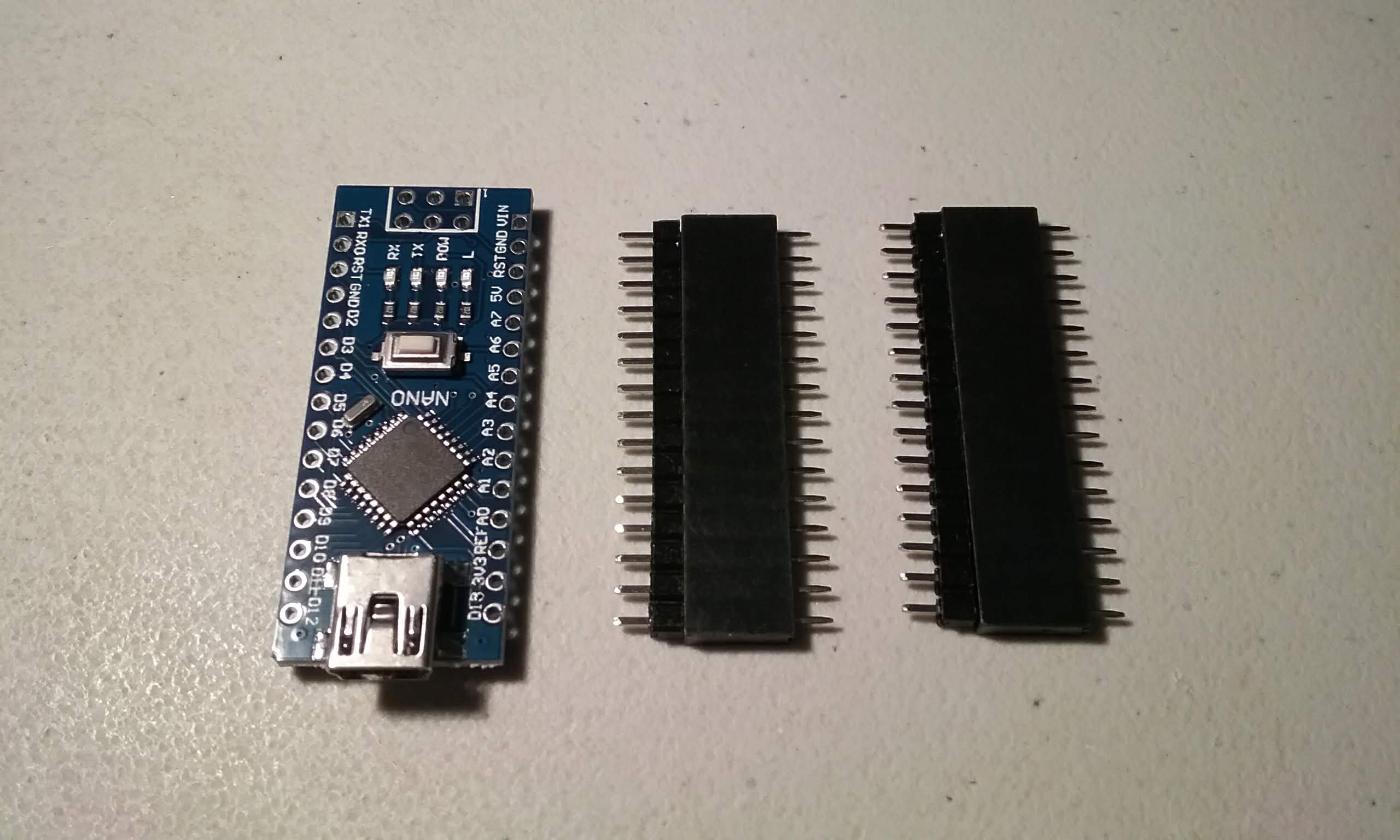
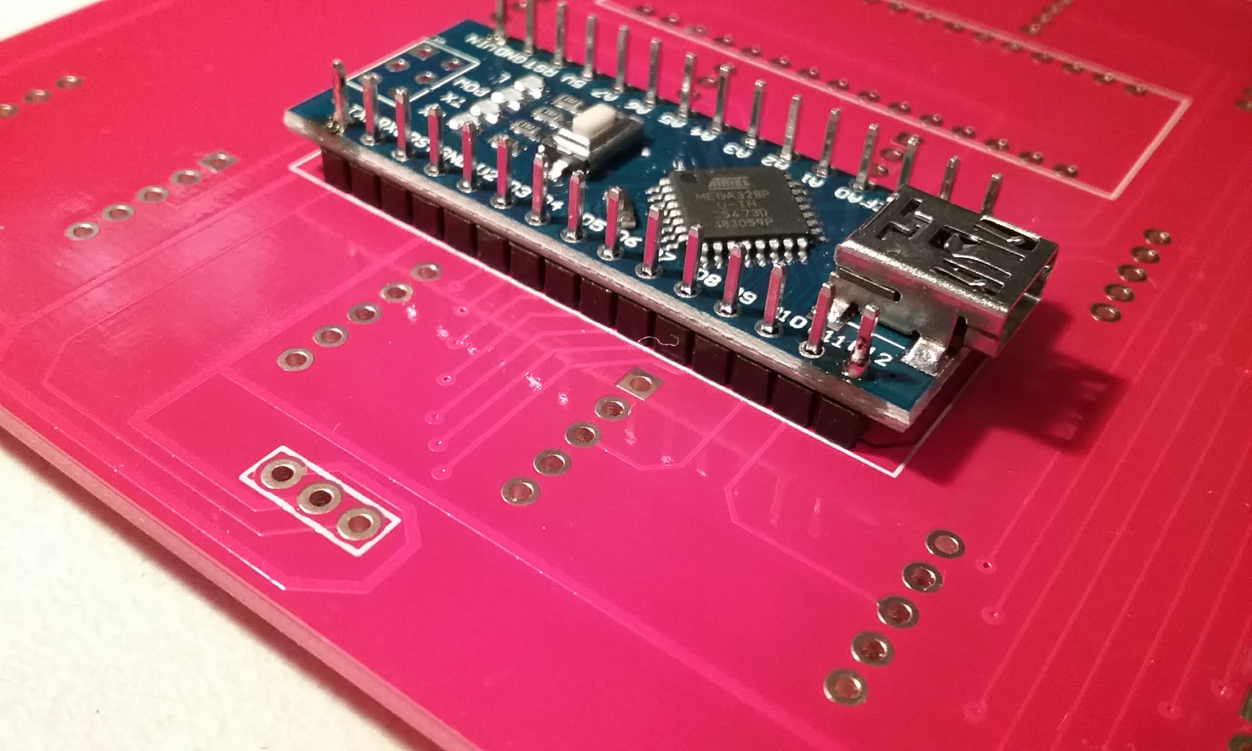
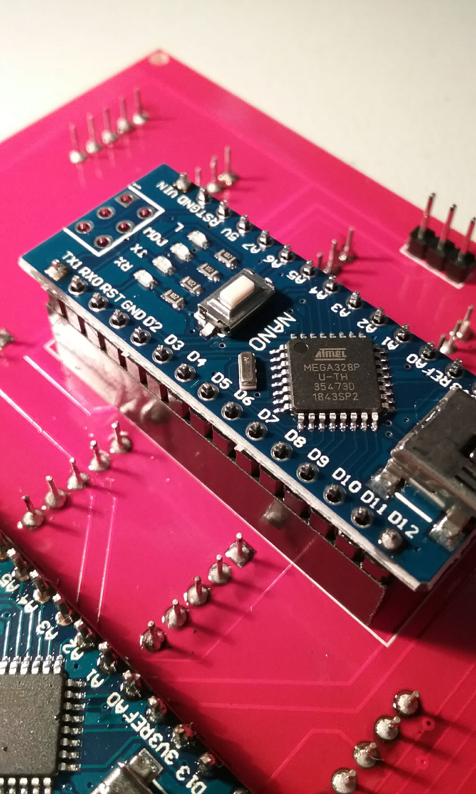
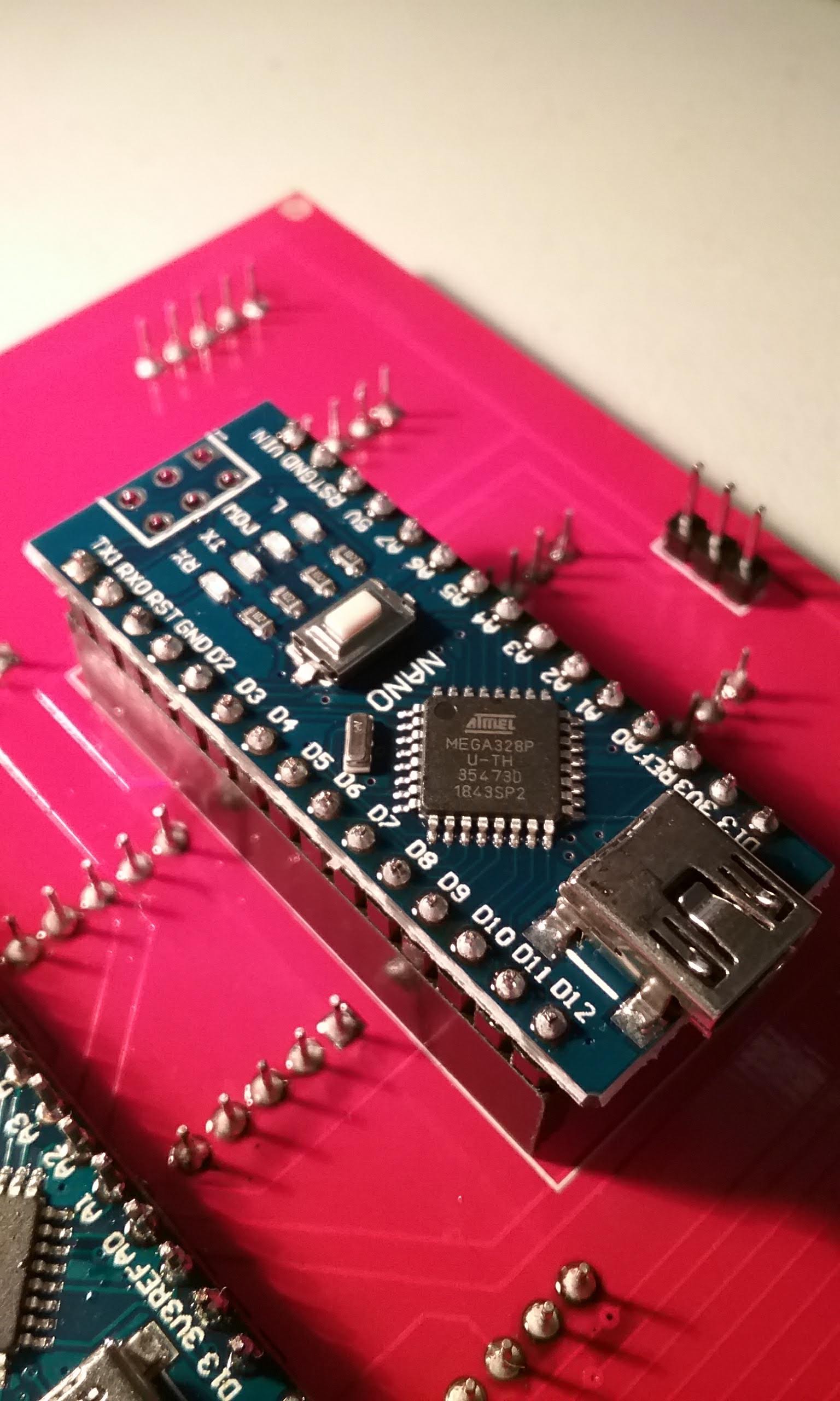
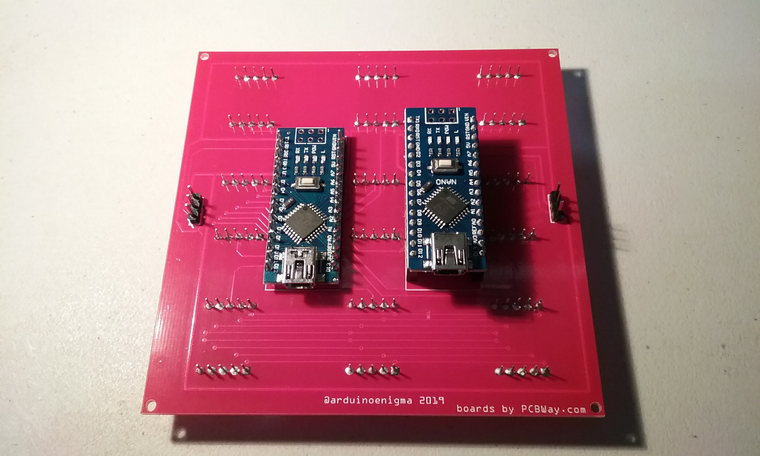
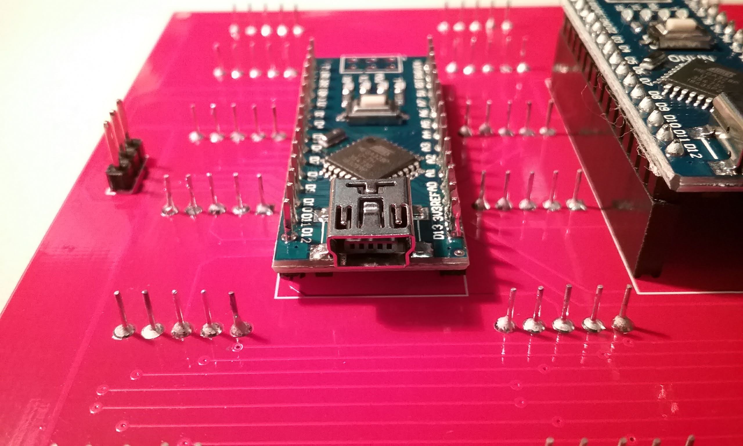
Unpack an Arduino Nano, two if building a master tile. The 6 pin connector can be ignored.
![]()
Flip the board and insert the headers short pins first. We don't want pins sticking out of the front.
![]()
And now is a good time to start heating the soldering iron.
![]()
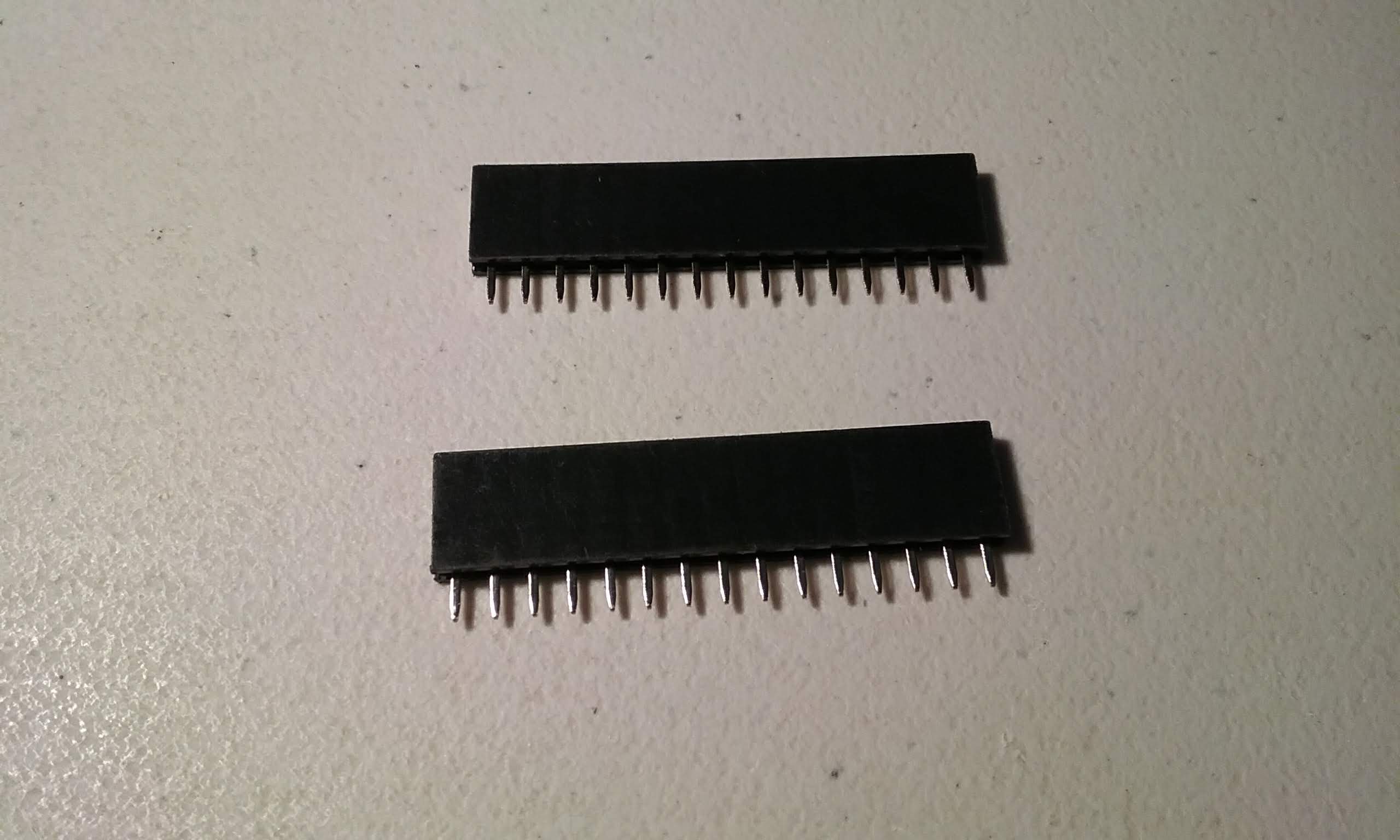
If building a master tile, prepare two 15 pin female headers.
![]()
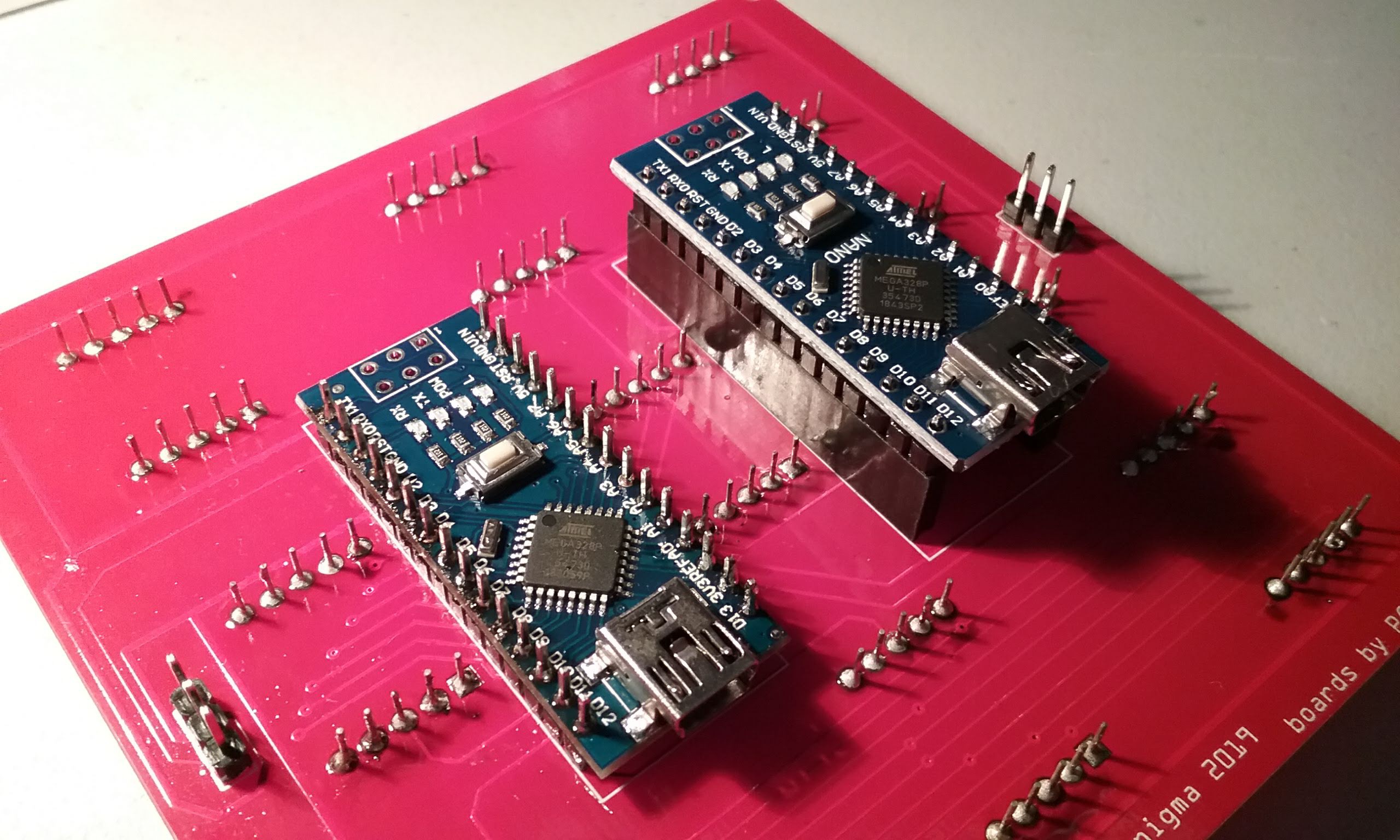
This Arduino Nano will become the master.
![]()
Insert the Arduino headers long end first into the female headers.
![]()
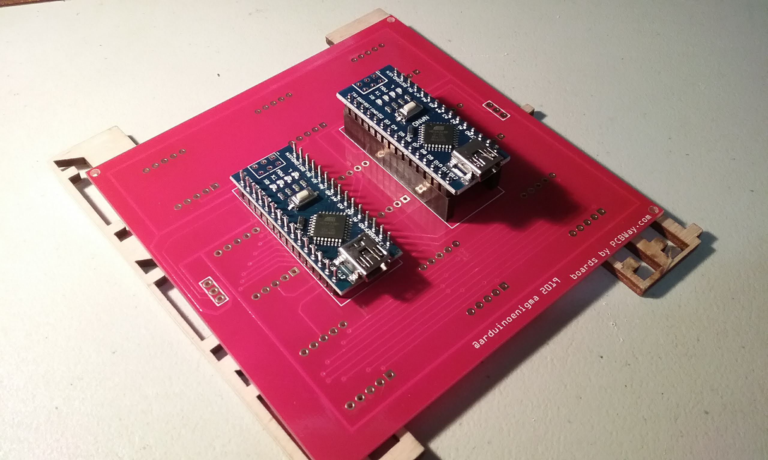
And here we are mocking how the Arduinos go on the tile. The display Arduino has the short side of the pins inserted on the board and the master Arduino goes into headers.
![]()
Mocking how the Arduinos will look.
![]()
Get the solder ready. I like this Alpha Pure Core Water Soluble Flux Solder, makes the boards easier to clean at the end of assembly.
![]()
Start by soldering the four corners of the headers, make sure everything is fully inserted.
![]()
Next, continue soldering the rest of the pins.
![]()
Flip the board.
![]()
And solder the four corners.
![]()
Continue by soldering the rest of the pins.
![]()
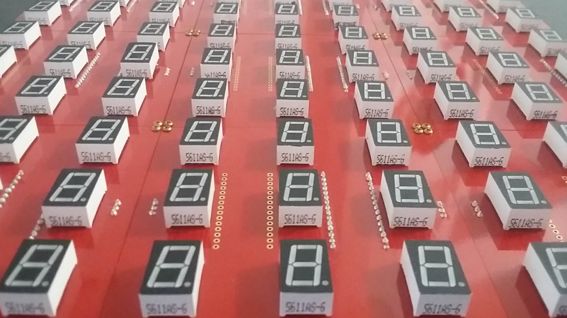
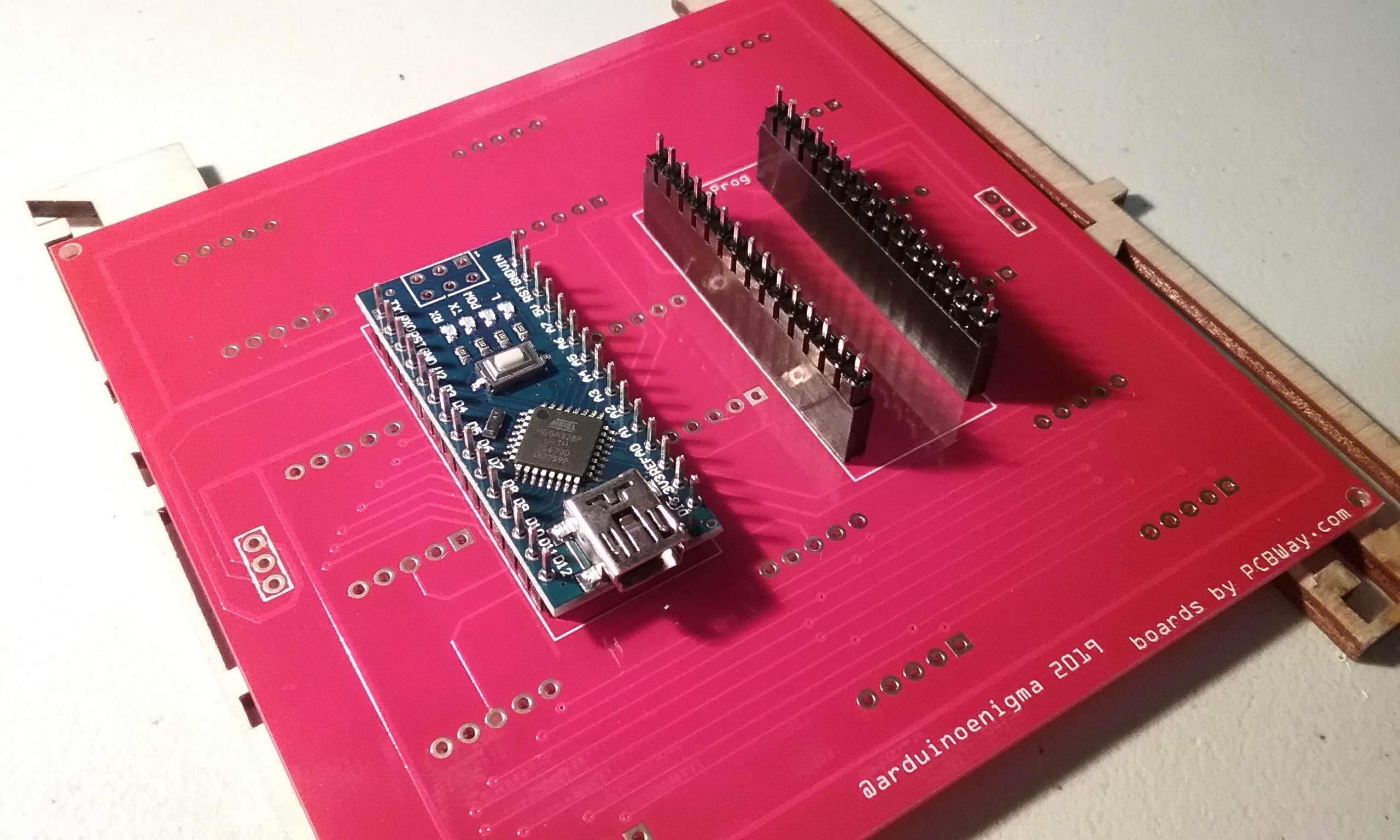
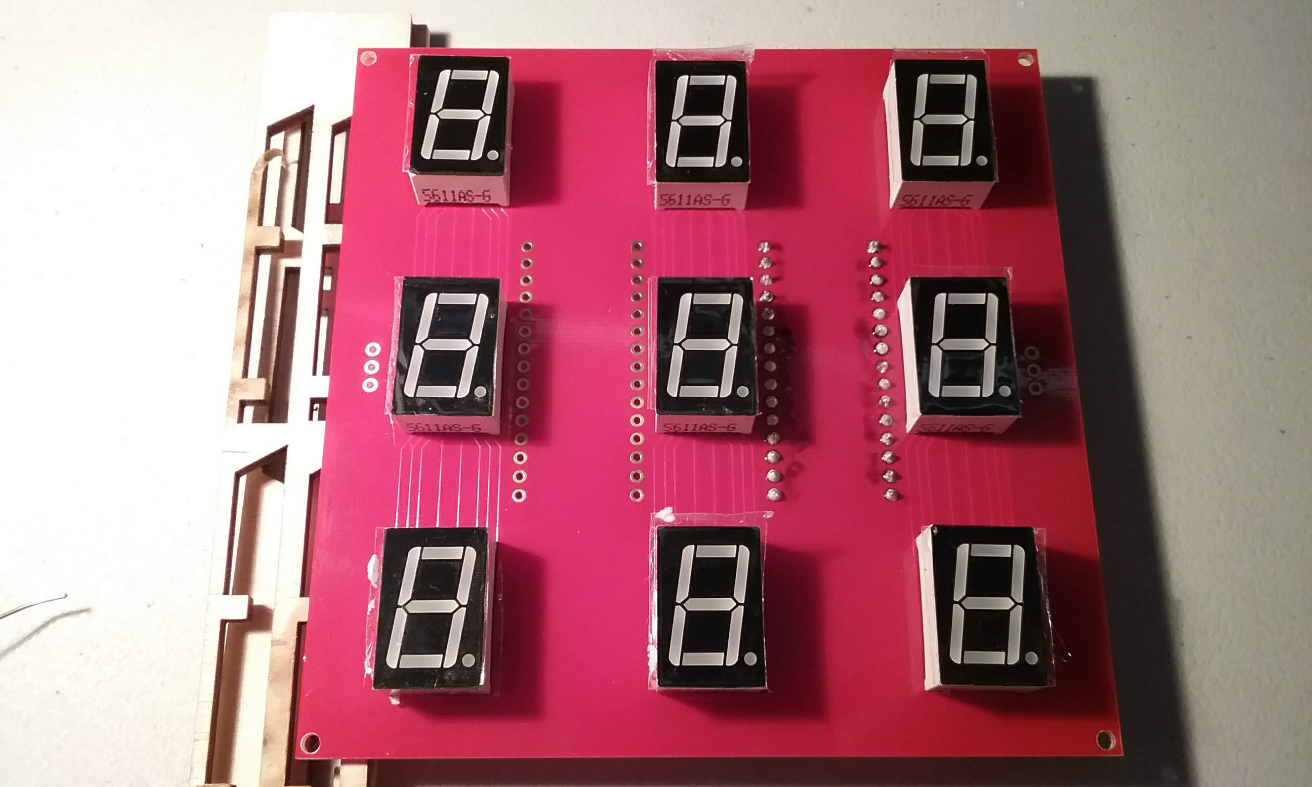
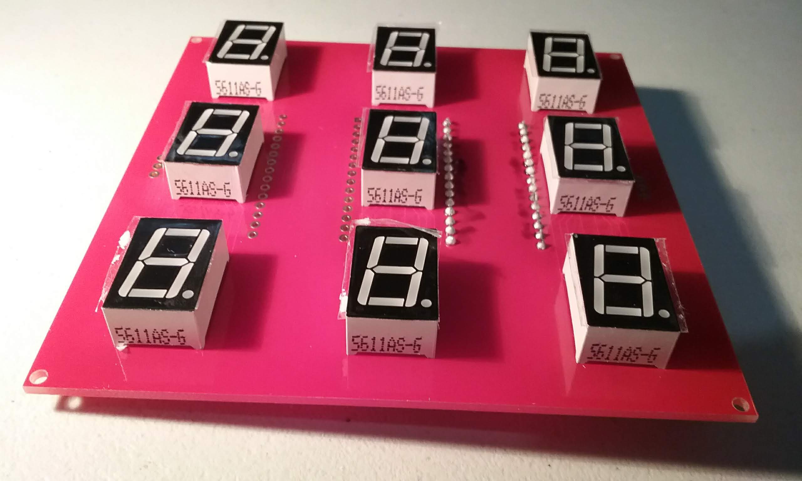
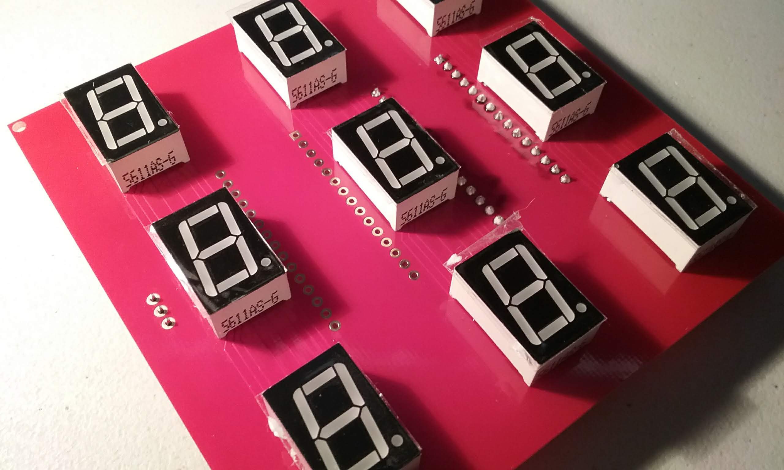
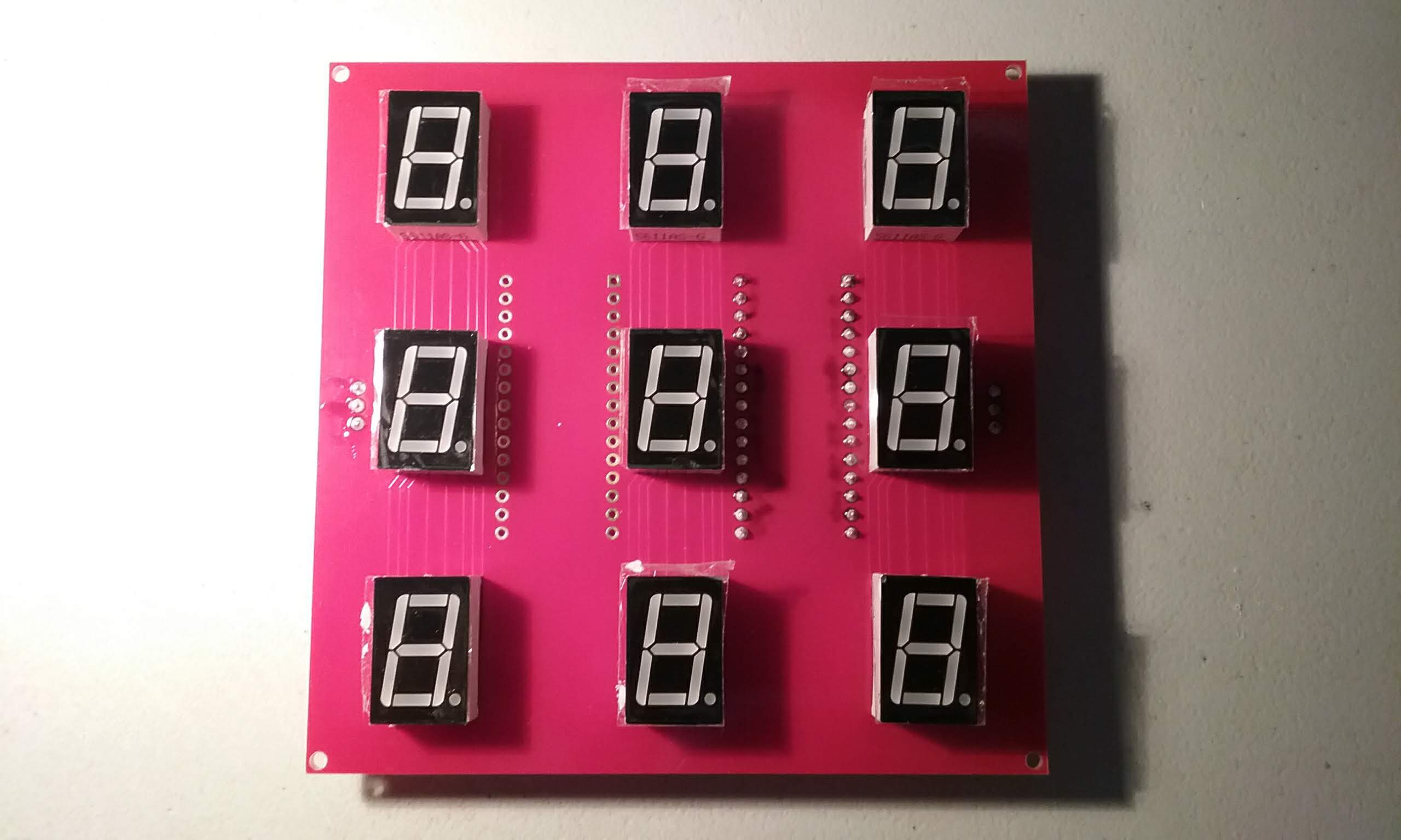
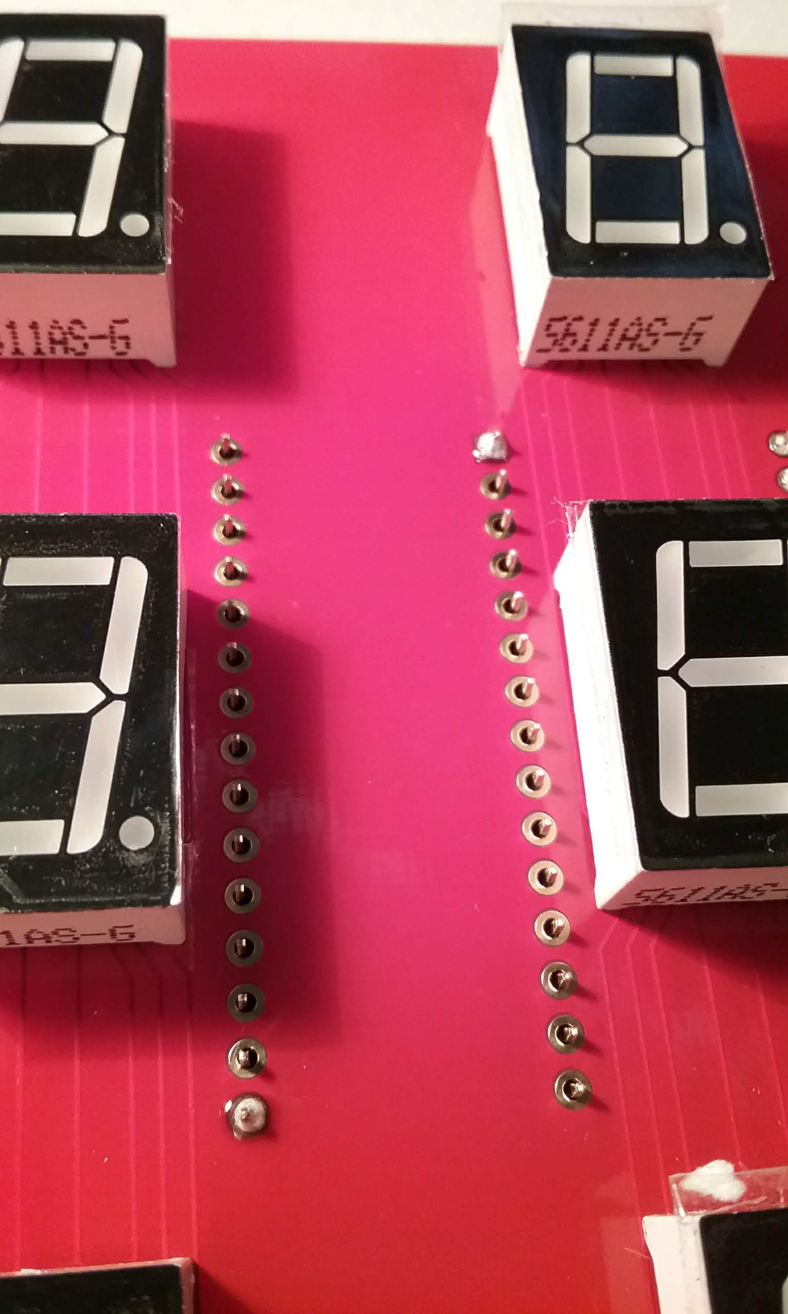
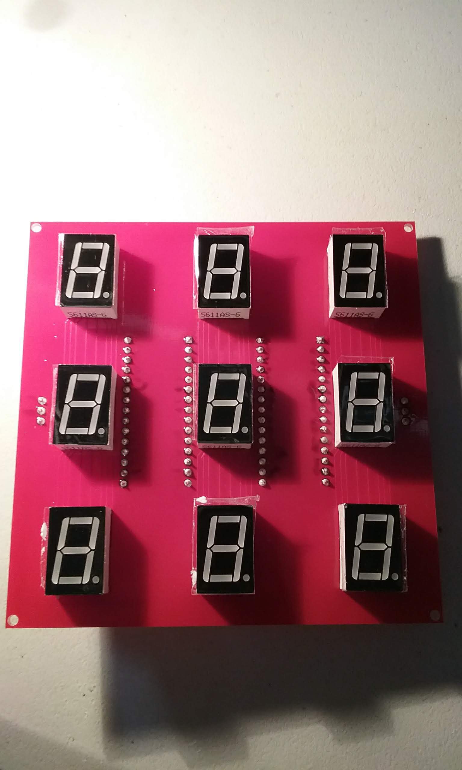
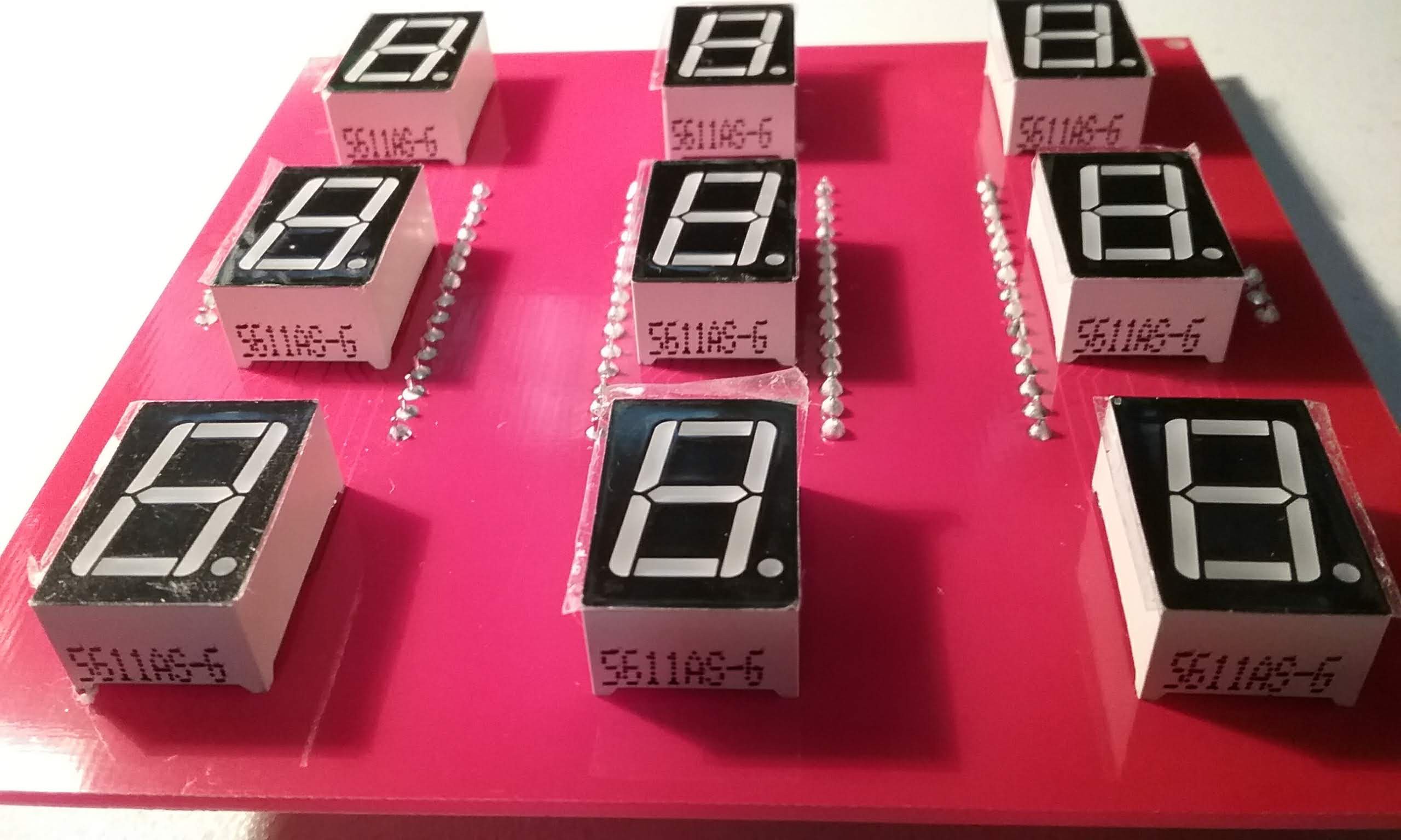
Next, insert the displays on the board. These have been pre-tested in a bread board to make sure all the segments work. Make sure the decimal point is facing down. Note that the display arduino is on the right half of the board.
![]()
Carefully (the displays fall out easily), flip the board.
![]()
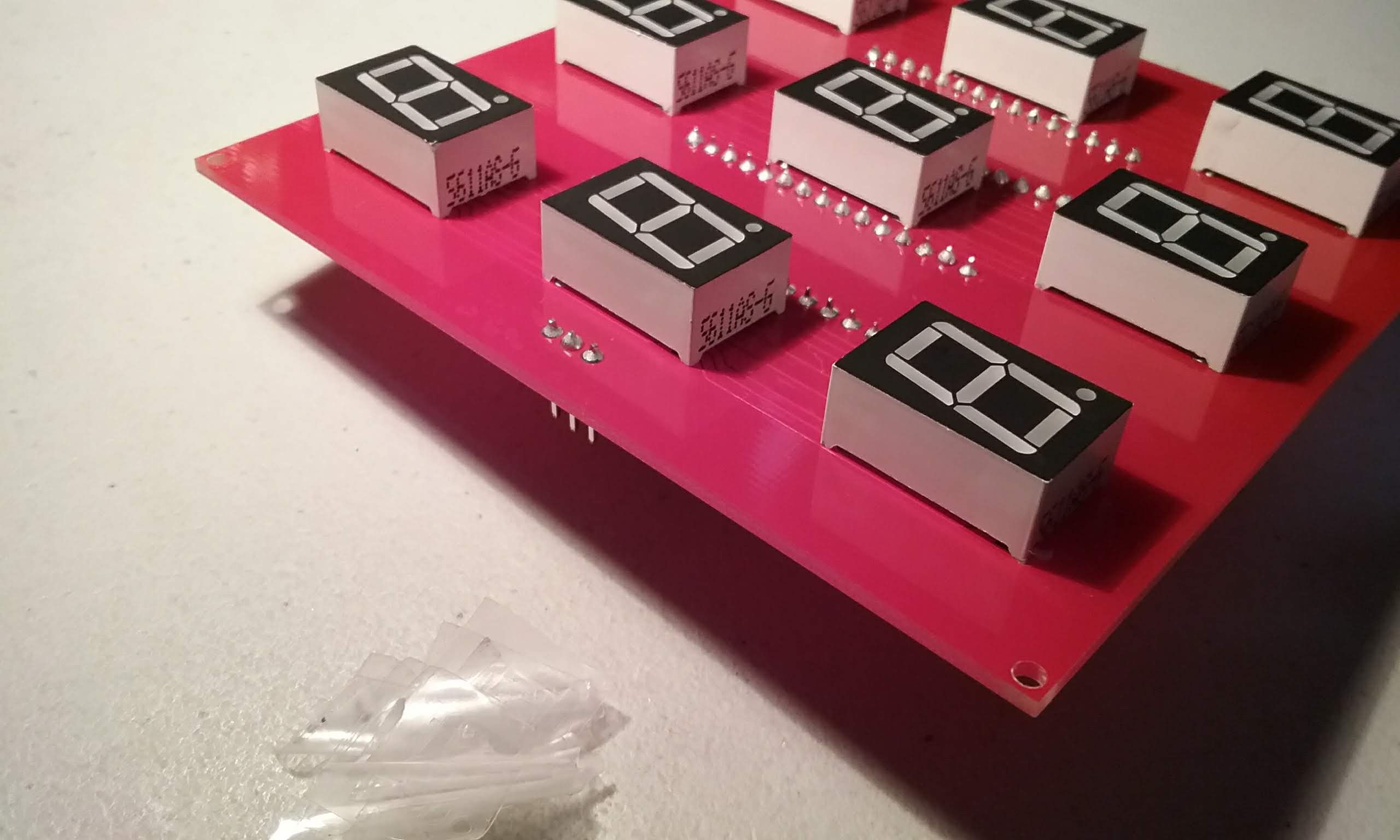
While pressing down on the board, solder one pin on each display.
![]()
Flip the board and make sure the displays are sitting flat.
![]()
Then finish soldering the rest of the pins.
![]()
Make sure all the pins are soldered and no solder bridges exist.
![]()
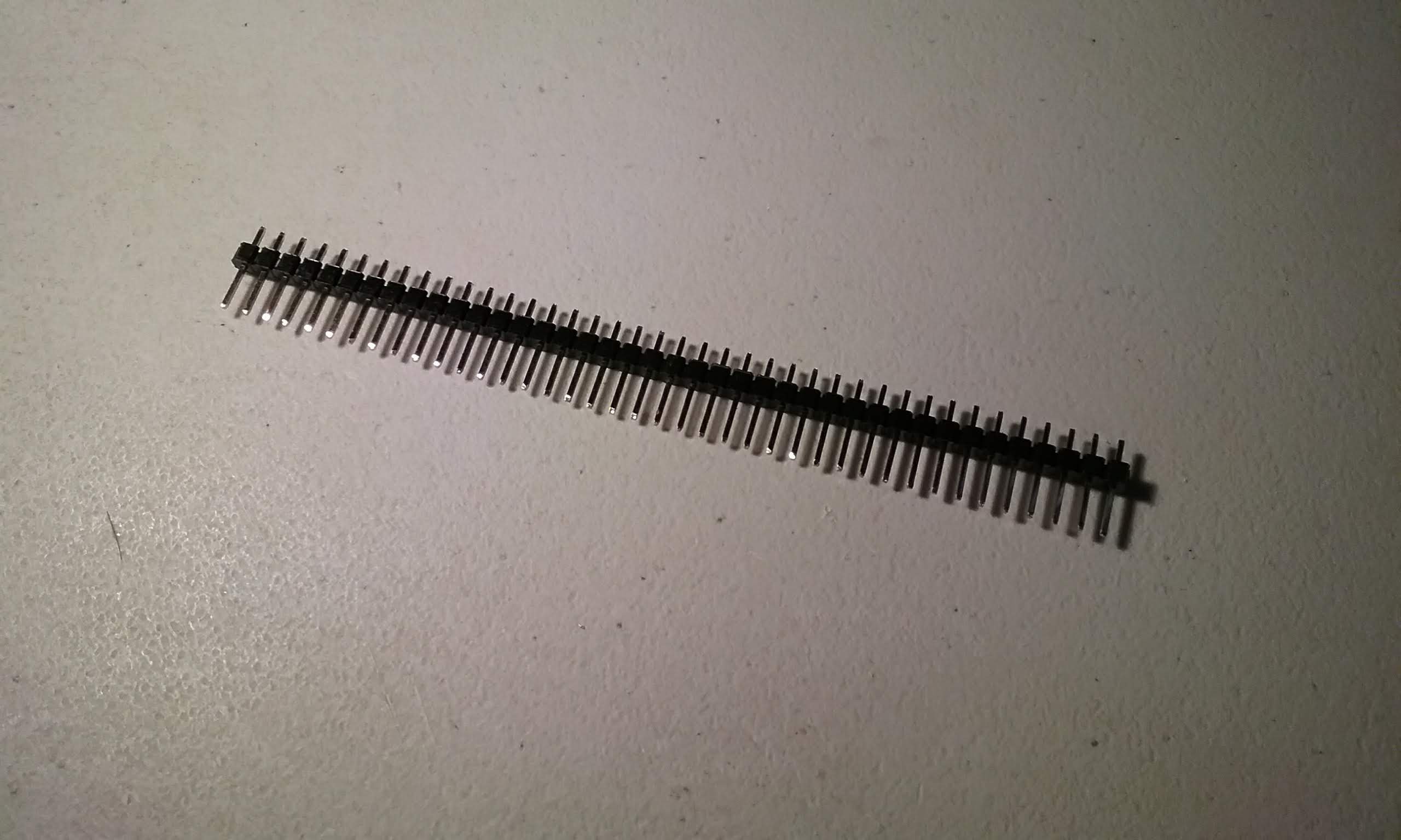
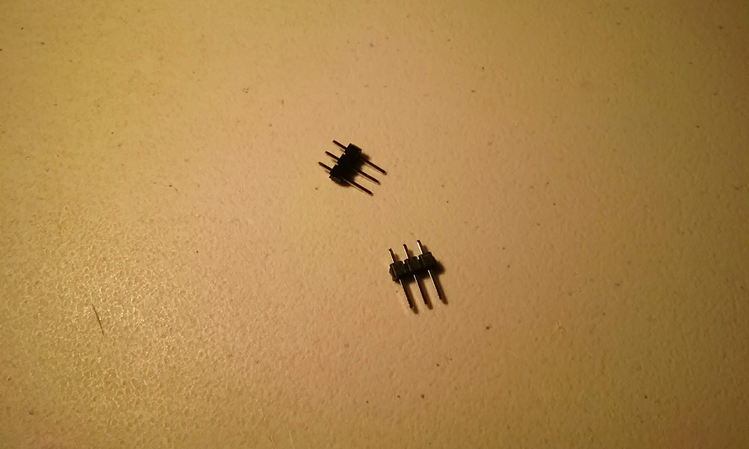
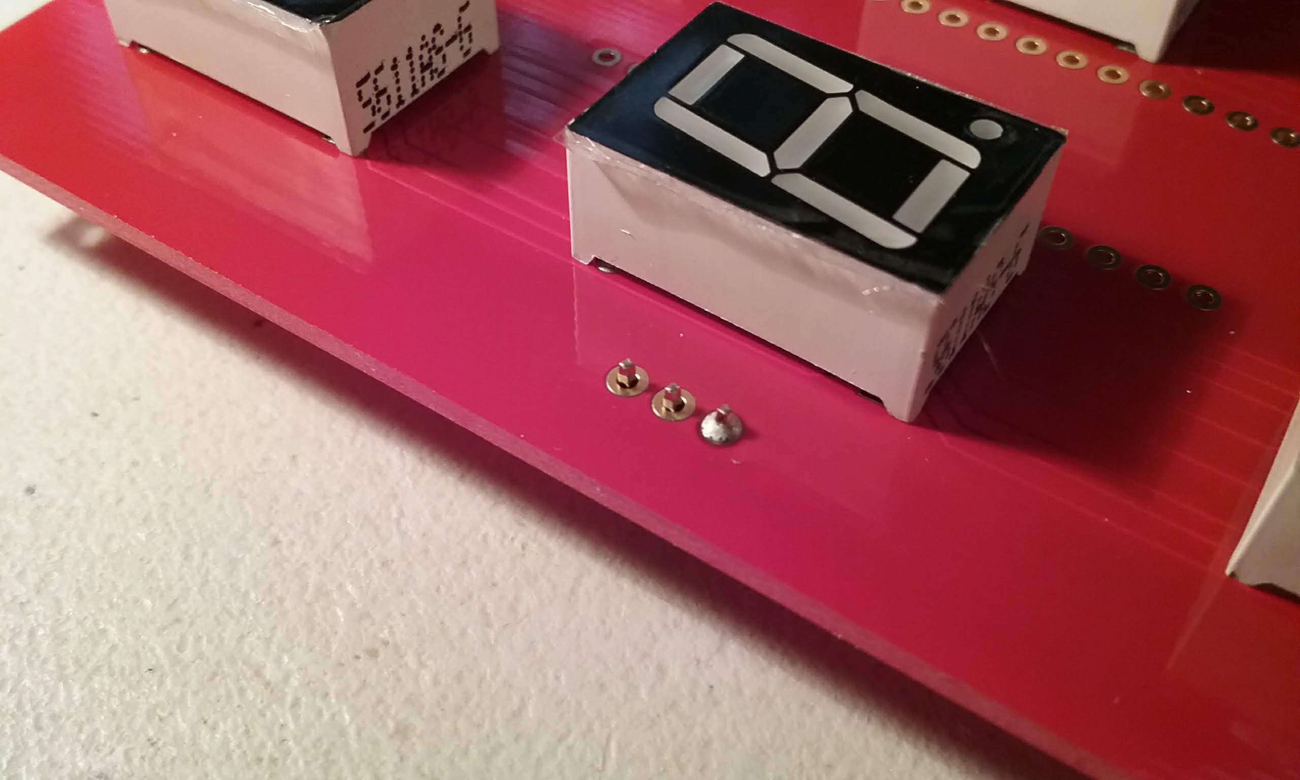
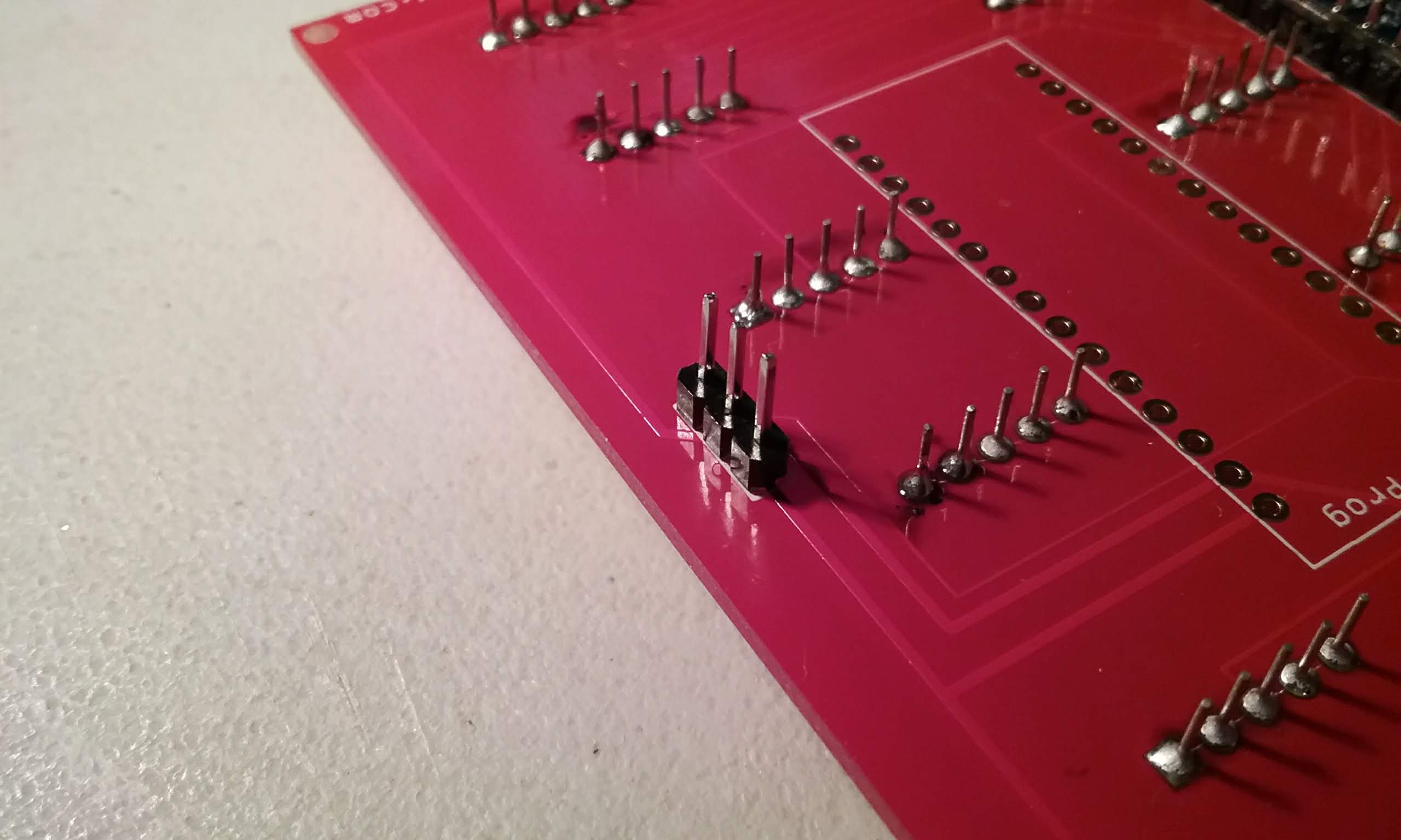
Next, prepare a pin header, we need 2 three pin headers.
![]()
Break off two three pin headers.
![]()
Place the short end on the bottom side of the board.
![]()
Carefully flip the board, ensure the pins are sitting straight.
![]()
Solder one pin.
![]()
Make sure everything is sitting straight.
![]()
And solder the rest of the pins.
![]()
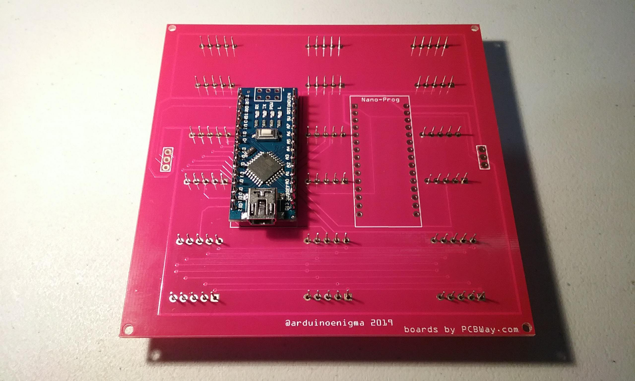
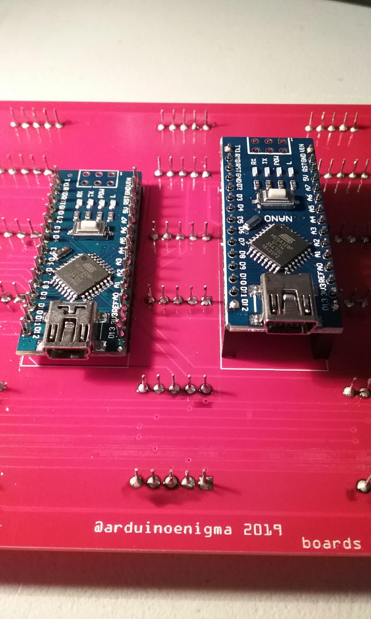
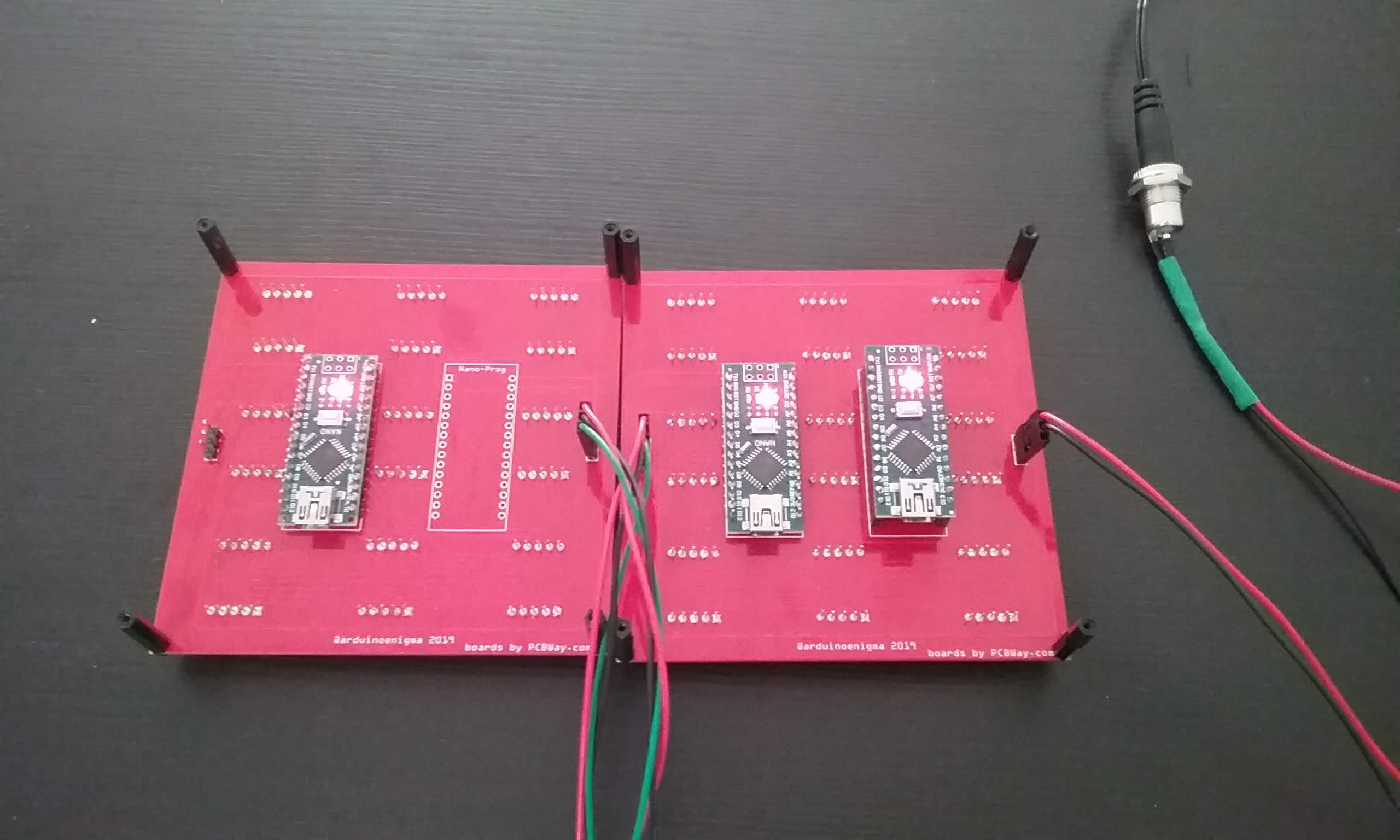
And here is a fully soldered tile board. The steps after this one are to make a master tile.
![]()
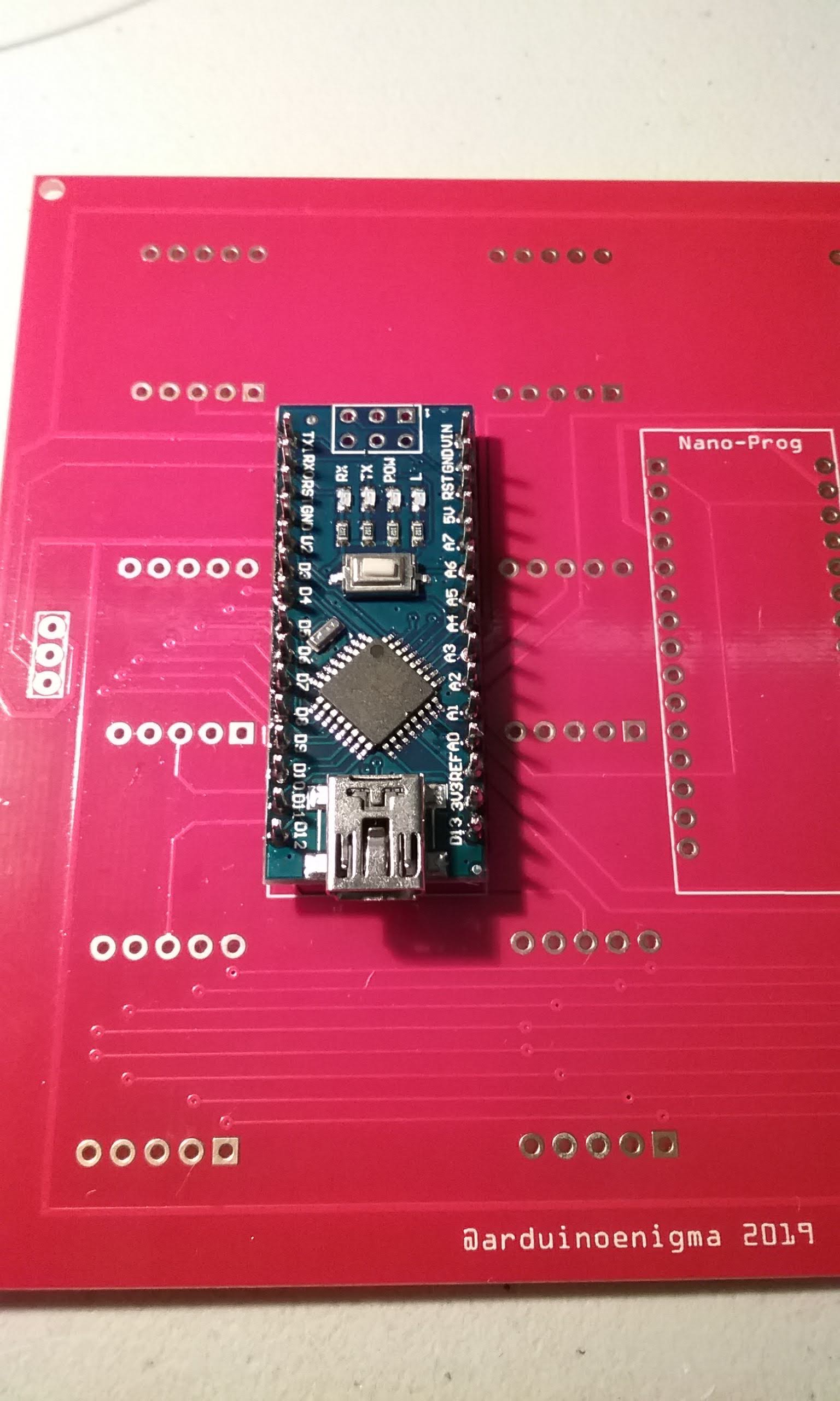
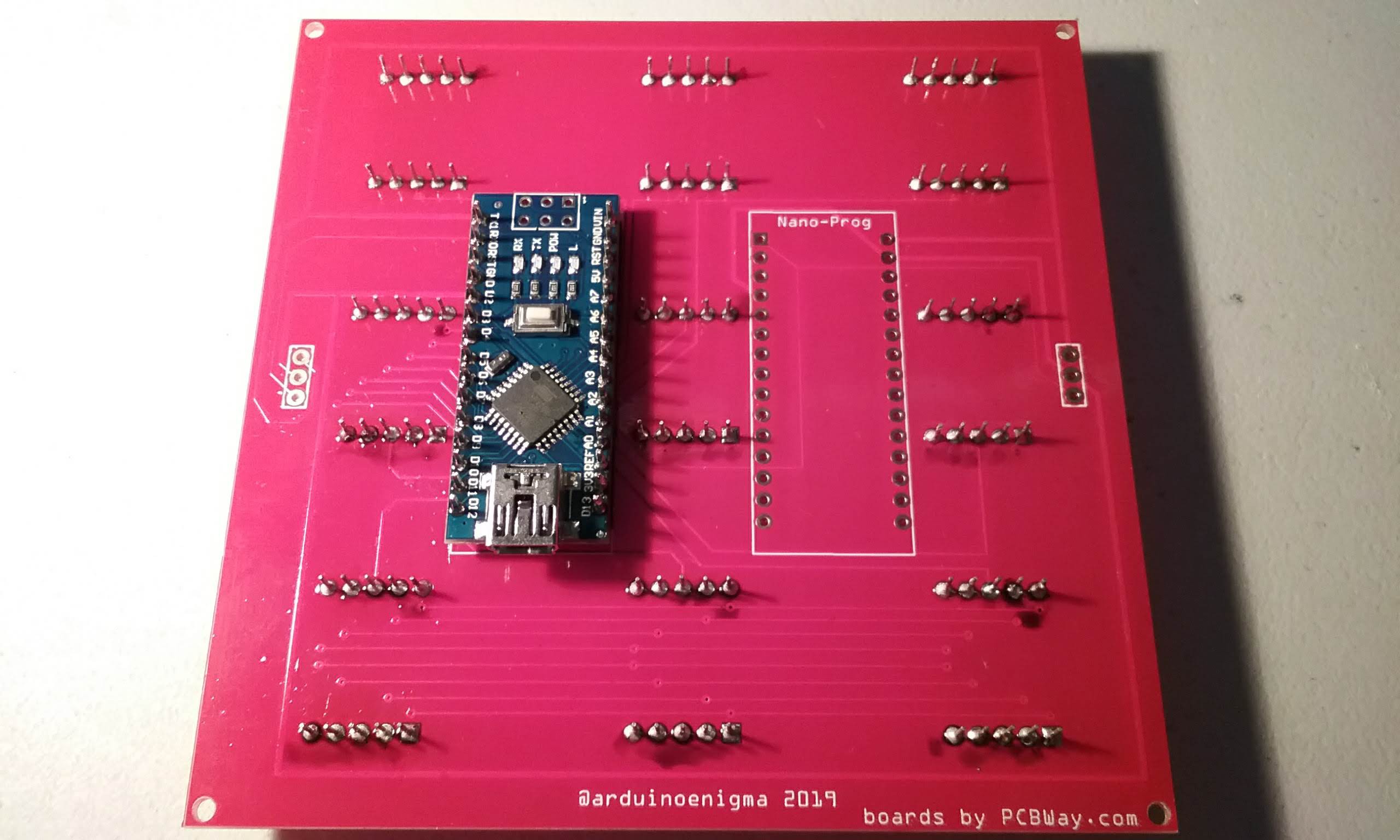
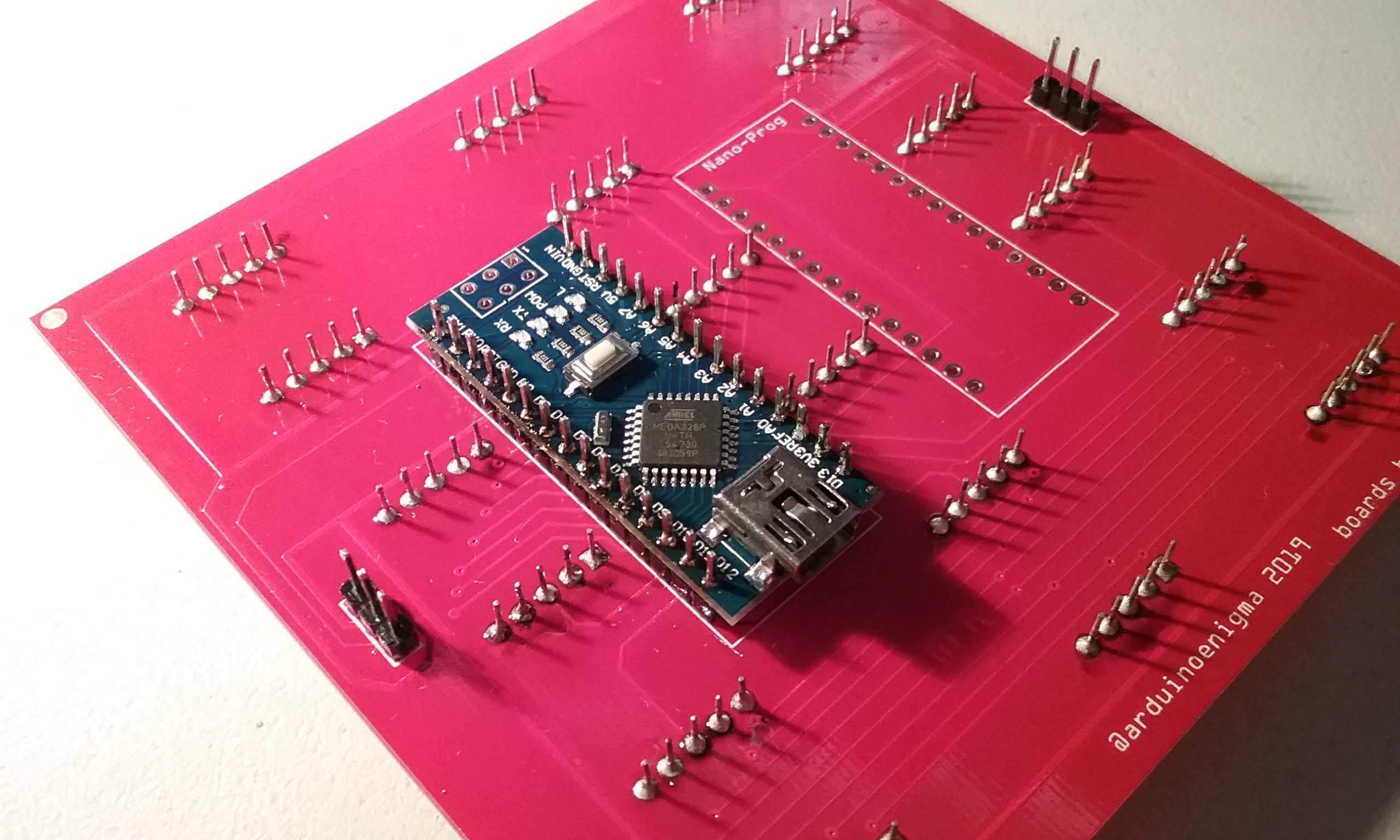
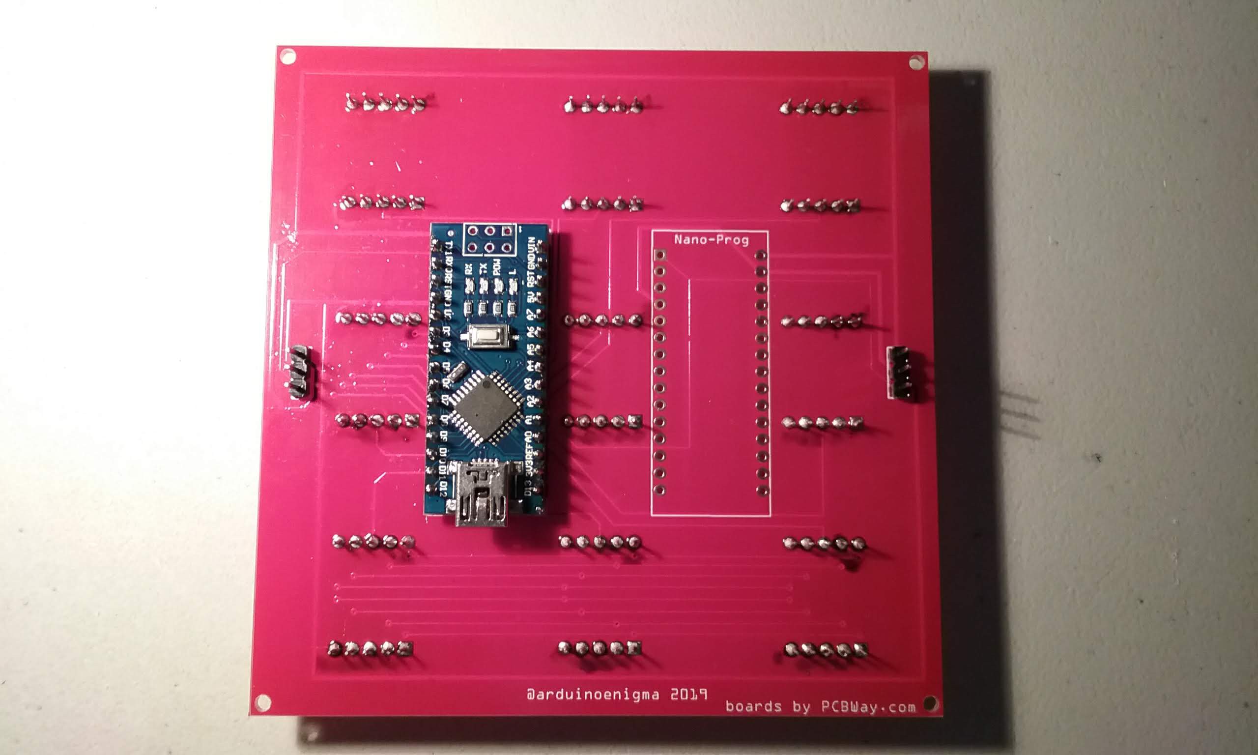
To make a master tile, start by placing the female headers on the bottom side of the board on the footprint labeled Nano-Prog.
![]()
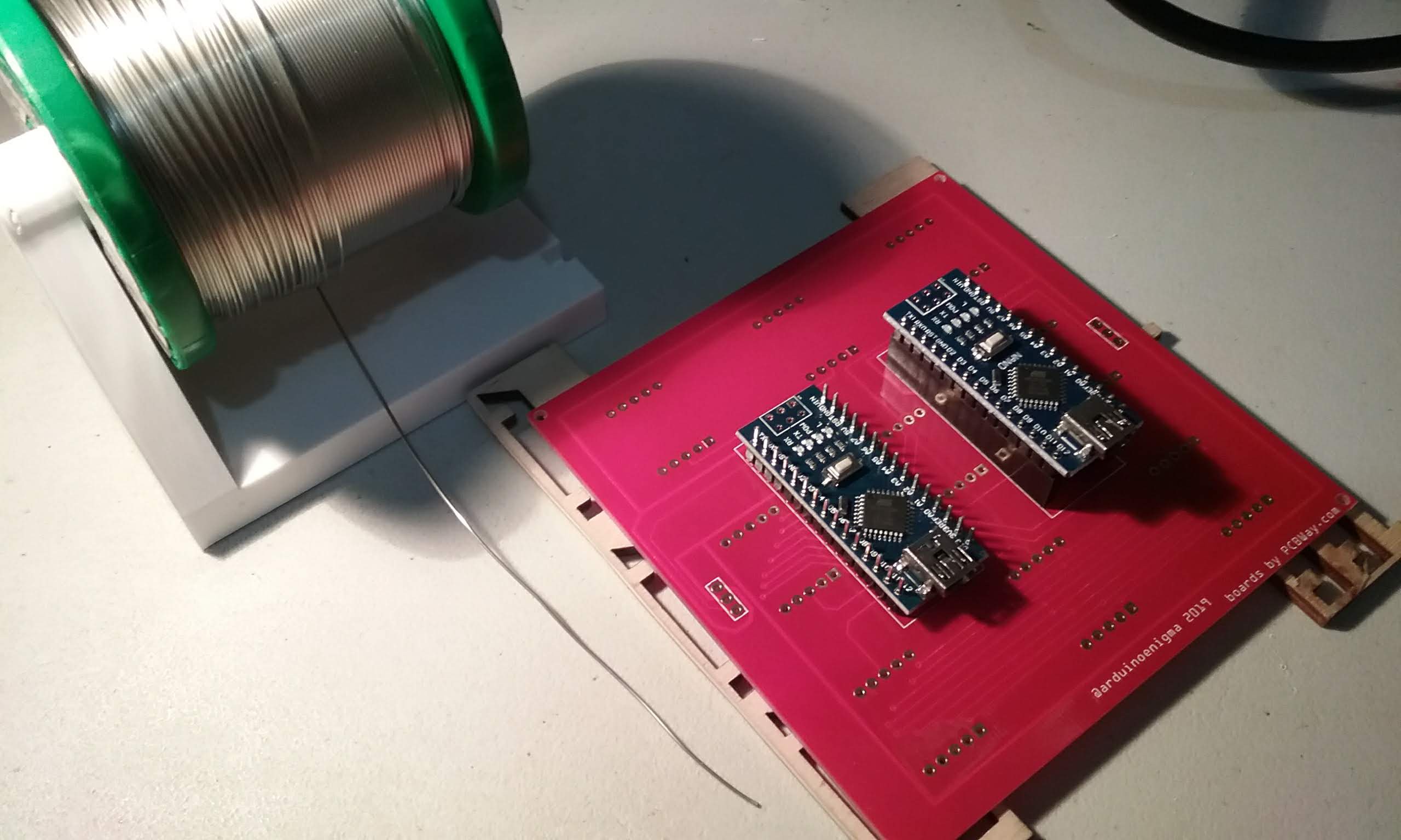
Insert the Arduino Nano on the headers.
![]()
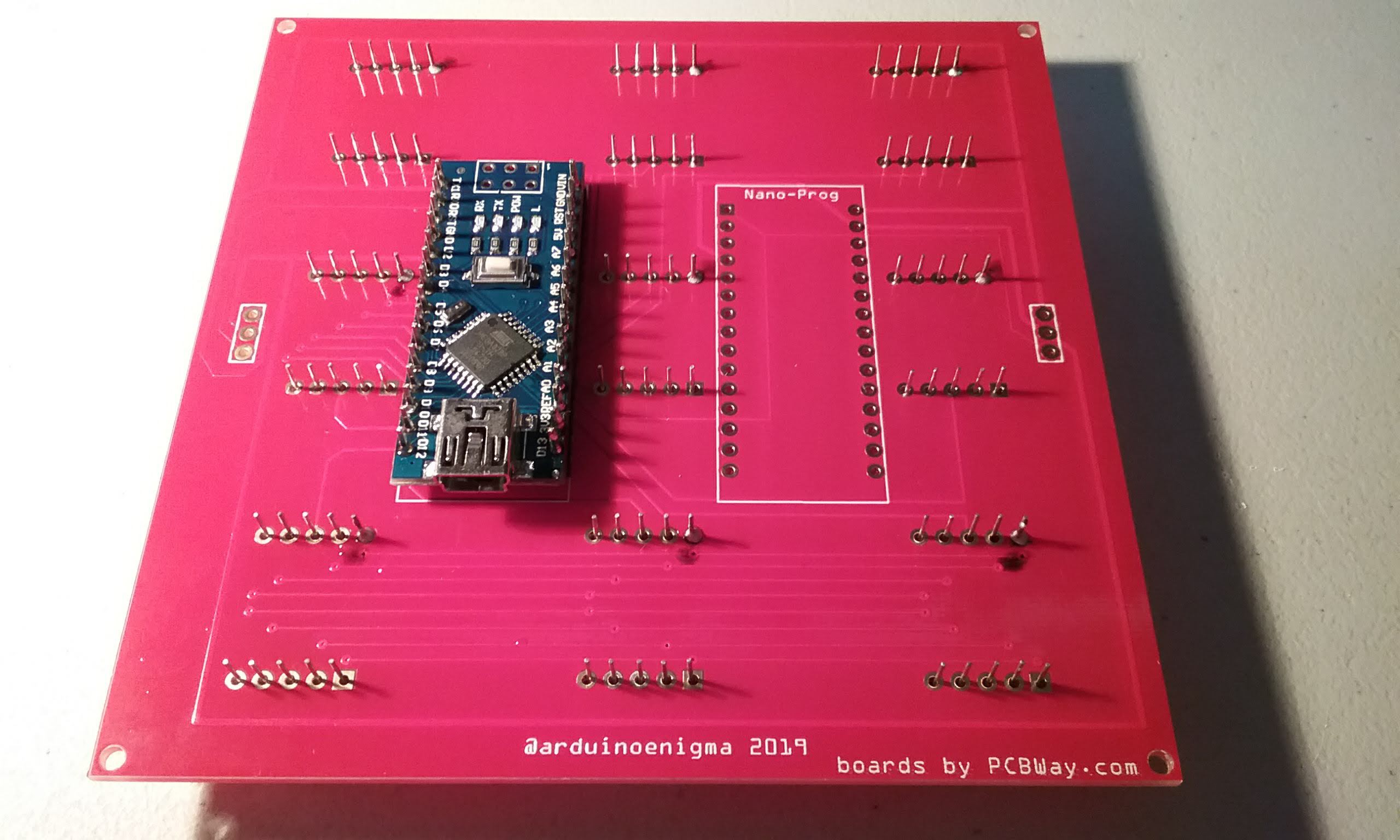
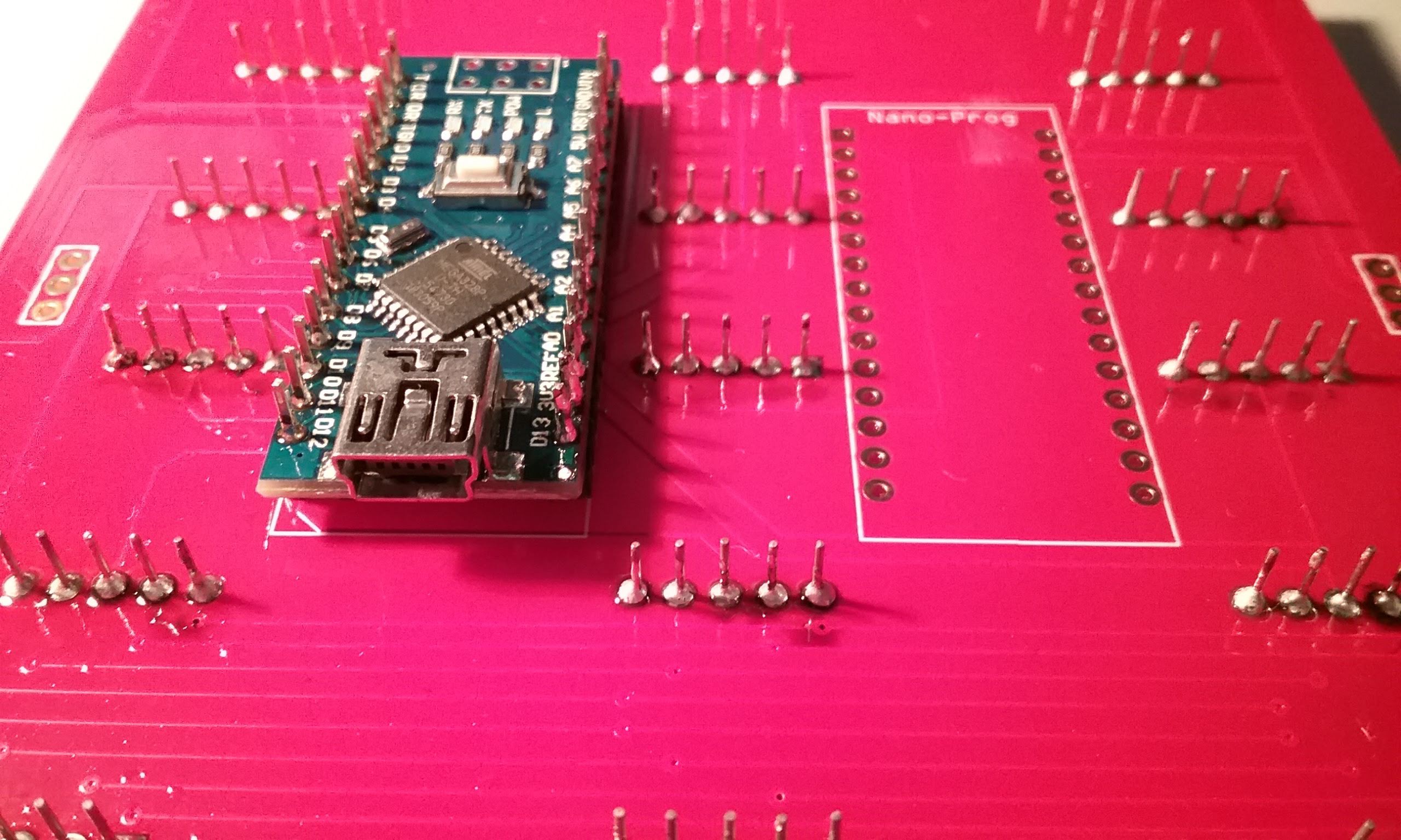
Press everything down to ensure the pins are fully seated and solder the four corners.
![]()
Flip the board and solder the corners on the headers. Be careful that the soldering iron does not touch the displays.
![]()
Flip the board over.
![]()
And solder the rest of the pins.
![]()
Flip the board and solder the rest of the header pins.
![]()
Next, using a toothbrush and water, clean the flux from the board. Looking good!
![]()
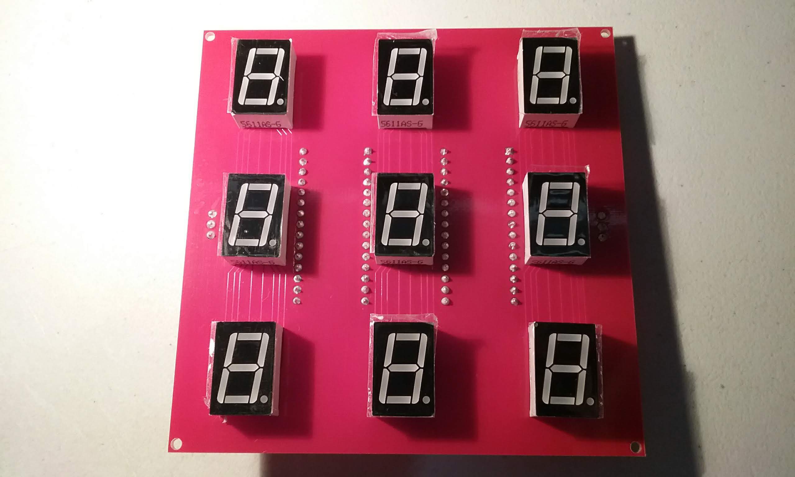
This is what the board will look like once cleaned.
![]()
The front looks symmetric.
![]()
Looking good.
![]()
The last step is to peel the stickers from the displays.
![]()
The next step is to program the board.
Load this sketch into the tile.
https://gitlab.com/arduinoenigma/seven-segment-art-installation/tree/master/Board100x9x13
Hold down the reset button on the Nano-Prog Arduino while programming to prevent it from loading down the Rx line. If the tile software has to be reloaded, hold down the reset button on the tile before the one being programmed to make its TX pin go to high impedance and not interfere with the programming.
Load this sketch into the Nano-Prog Arduino, since it is the first on the string and there is nothing connected to its Rx line, it can be programmed normally.
https://gitlab.com/arduinoenigma/seven-segment-art-installation/tree/master/Board100x9x13-Master
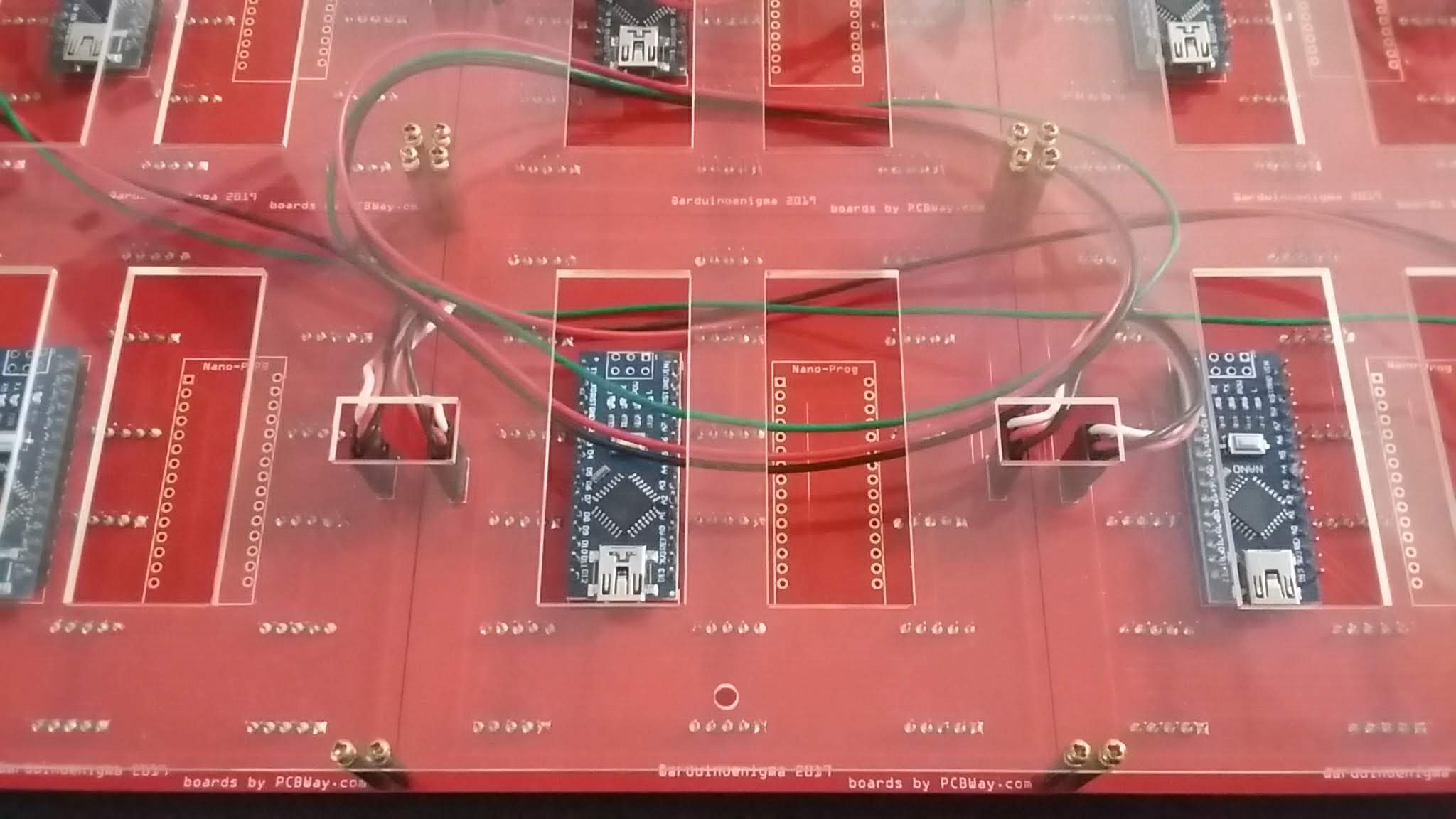
Next is to put standoffs on the board, mount them to a base and wire them.
-
Falling streamer using better data structures
03/17/2019 at 15:01 • 0 commentsIt's just an array, but it allows one falling streamer per column. Next step is to have not only one, but TWO streamers per column. By adding yet another array, we can have independent falling speeds.
-
Scaling it up...
03/16/2019 at 15:55 • 0 commentsHere is a falling streamer crossing tiles:
The software for this has been uploaded to gitlab:
https://gitlab.com/arduinoenigma/seven-segment-art-installation/tree/master
-
Adding Layers to the Onion
03/11/2019 at 05:32 • 0 commentsAdded some functions to the sketch running on the Master Arduino to make displaying things easier:
https://gitlab.com/arduinoenigma/seven-segment-art-installation/tree/master/Board100x9x13-Master
void SendCommandXY(byte XL, byte YL, byte CMD, byte VAL)
{
  Translate(XL, YL);
  SetCMD(CMD);
  SetVal(VAL);
  TxSetChecksum();
  PrintTxFrame();
}
Ultimately the goal is to manipulate arrays and have a function that scans what changed and send the commands to display that.
-
Done Soldering...
03/10/2019 at 15:38 • 0 commentsAnd finally we are 100% done soldering, time to put the soldering iron down.
Shown below are the first two tiles in their final configuration while running off a 6V wall adapter.
![]()
The first (or last) board in the series is fed power via an adapter cable. The first board in the series has an Arduino Nano mounted in headers. This Nano is responsible for sending the commands for the animation that is going to run on the whole display. The Nano that is permanently mounted on the first tile receives the commands from the master, updates its internal arrays with the values to display and drives the displays. Any commands that need to go to downstream boards are relayed.
Next step definitely is to order the mounting plate and 20mm spacers.
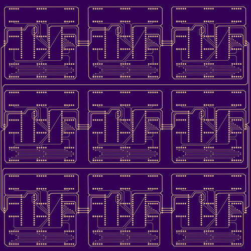
A Seven Segment Art Installation
A modular board hosting 9 seven-segment displays that can be daisy chained to make an art installation