-
1Source code
All the code and schematics for this project are in my github page https://github.com/jotatsu/TitanClock-RGB.
-
2Preparing
![]()
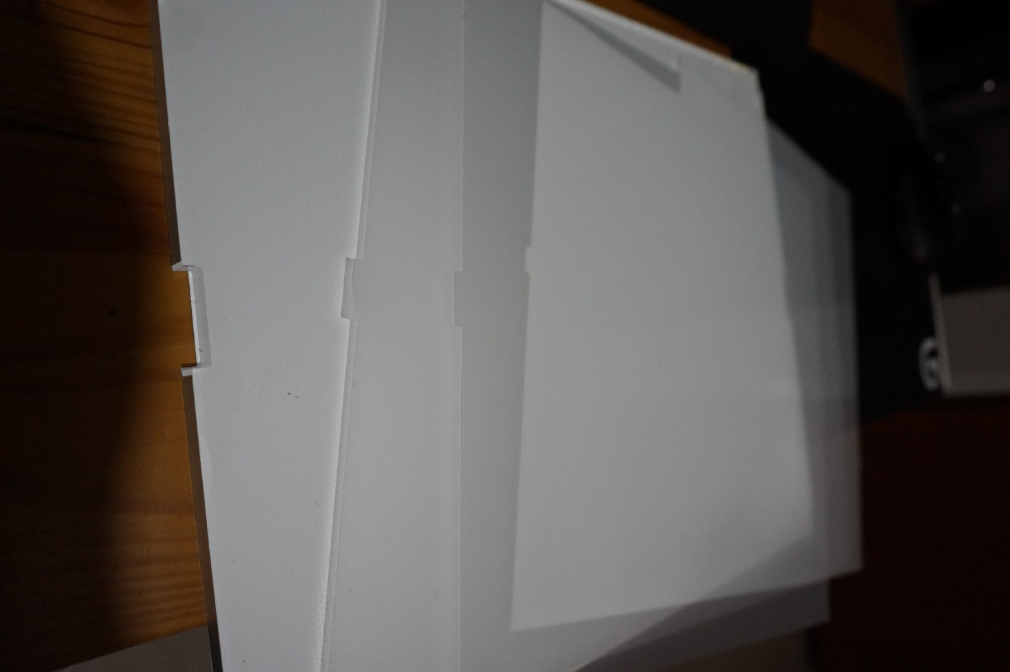
The first thing you need to do is to dissemble your LCD screen, depending on the model you have you might need to remove some screws, unclip flips, use a hammer, etc. The objective is to get to the backlight diffuser, that normally should be an acrylic sheet with dots marked in the back and some plastic sheets in the front and back. Remember the way the sheets are sandwiched (order and orientation) as you will need to use the same structure when you put them in the segments.
-
3Cutting
The objective of the cut is to generate a segment with this shape (note that the sizes are examples for my 15x28cm 7 segment display):
![]()
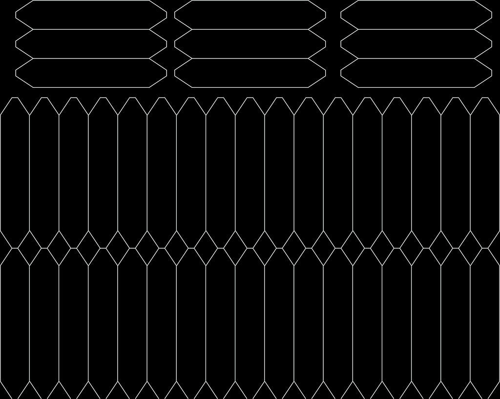
Depending on the size of the acrylic diffuser and the desired size of the segments, design a cutting path for the laser to create the segments. In my case I did 48 segments, more than enough for 4 full digits. The original acrylic is 1cm thick from a 21-inch diagonal screen.
![]()
This process can be done using a saw, but it will be a lot harder to obtain consistent shape segments and after the cut you will probably need to sand and flame polish the borders in order to make then optically clear.
You will also need to cut the other plastic sheets in the same shape and size as your segments in order to replicate the original backlight sandwich. Also to replicate the metallic exterior of the LCD backlight cut the craft aluminium in this shape (respecting the size for your particular segments, leave some 0.5-1.0 mm extra to account for the material thickness):
![]()
-
4Assembly
The assembly is pretty simple:
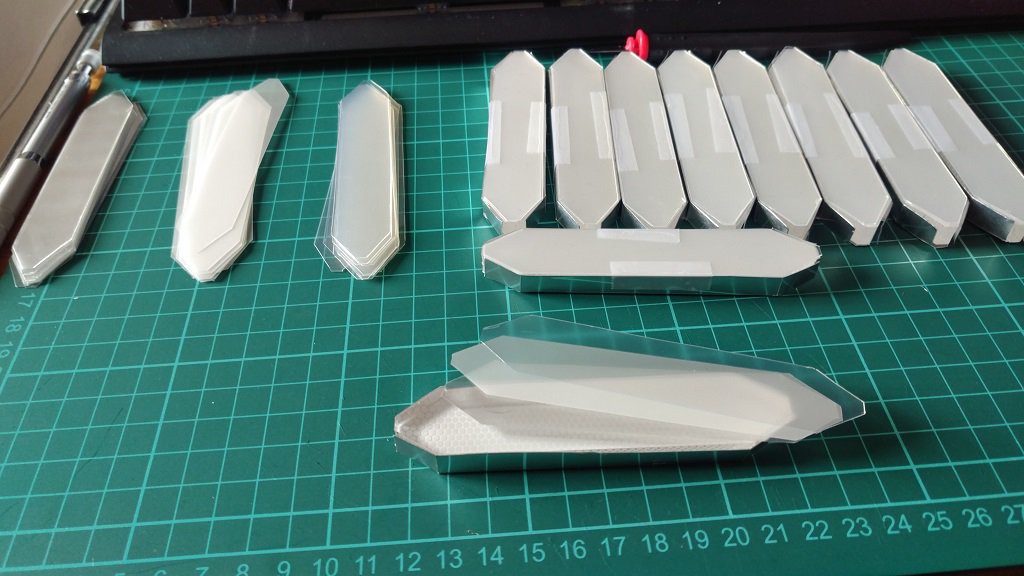
- Fold the aluminium sheet along the lines , if your aluminium sheet is to thick you can score it with the x-acto before folding it.
- Recreate the acrylic and plastic sheet sandwich of the original LCD backlight. Put it inside the the folded aluminium sheet
- Glue the WS2812b to each of the flat ends of the segment
![]()
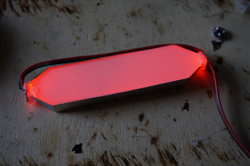
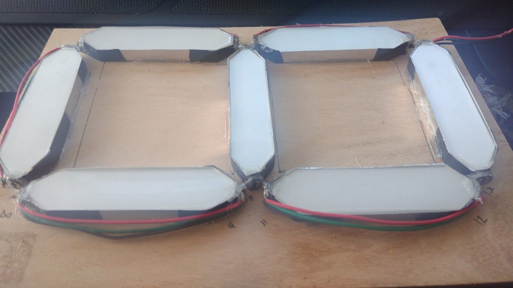
That’s it. You should end up with something like this:
![]()
This one is already wired as i was testing for lightning uniformity. This one was also corrected later as you can notice there is light leakage at the ends, this diminish the brightness and the energy efficiency. To correct this be sure that the ends of the ws2812b fit the aluminium encasing borders.
-
5Wiring
Wiring the WS2812b is pretty simple. You need to use 3 cables between each led, one for power, ground and the other one for the signal. Each led has a signal in and a signal out pin.Each segment should look something like this:
![]()
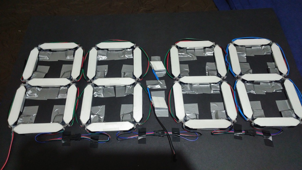
And the 4 7 segments for the clock:
![]()
Notice that i also have 2 mini segments for the clock dots, created with just one WS2812b per dot and parts leftovers from the acrylic laser cutting process
The github project contains the fritzing diagram for connecting the WS2812b, the ds3231 module and the capacitor.
-
6Finish
What is left to do?. Create a box for the clock. I'm using foamcore board as is cheap and lightweight the borders are reinforced with some wood rods.
Put the polirized film on the transparent acrylic sheet. I've used the soapy water technique with good results, as it avoids bubbles and crumples: I put the polirized film on "the inside" to hide the wiring and tape
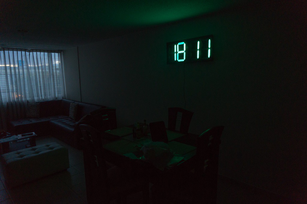
Program the arduino with the code in github. It's a simple program that will display the time and change the color every hour based on a hardcoded table in the program. There is some optimizations as to not display the left zero and to put a very low power color by night after 10:00pm until 6:00 am.
![]()
At night this run at about 400ma at 5v, during day depending on the color and intensity it can run to 1a, the display is calculated for a maximum of 2a or 10w, but for that you will need a 2a 5v smartphone charger or power supply.
 Camilo Alvarez


Discussions
Become a Hackaday.io Member
Create an account to leave a comment. Already have an account? Log In.