 Marcelo Valeria
-
1Get the components ready!
we will continue using the raspberry from the last project, so first if you have not hack the first project yet please go and check the instructions to configure the Raspberry Pi and the camera.
-
2What are we building?
The goal is to find an object in a picture and then target the camera to center the object.
For that we will use an Arduino. The Pi have pins too but cannot control by itself a servo. An Arduino can control servos without additional hardware and we can control the arduino from Mathematica.
![]()
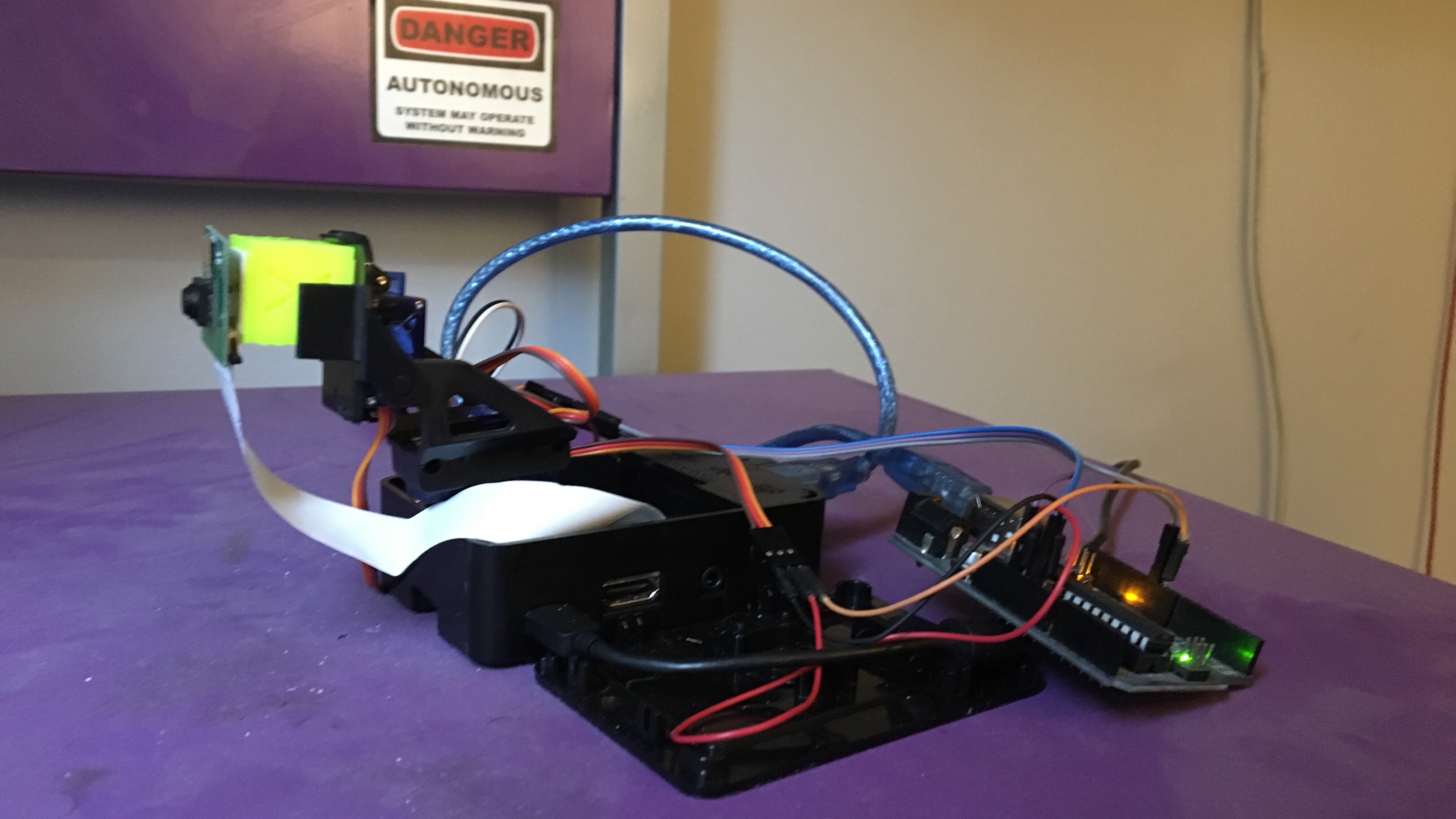
here we can see the raspberry (in a case), the camera mount (fixed on the case with two-sided adhesive tape) connected to the arduino (each servo is 5V, GND and Signal) and the camera taped to a fitting block. Load the sketch from the files section to the Arduino (follow this instructions if you are unfamiliar) and connect the data cable from the horizontal (X) servo to PIN 9 and the vertical (Y) servo data cable to PIN 10.
![]()
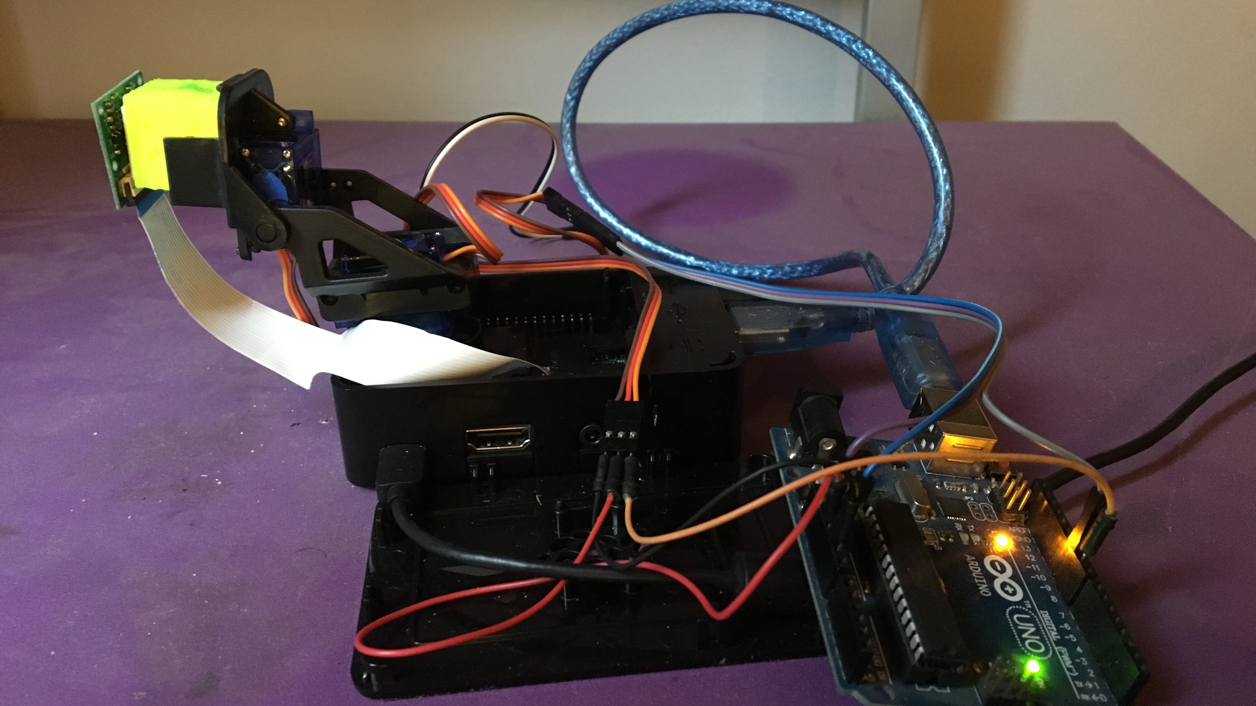
If everything is OK with the arduino and the servos from the camera mount after powering the arduino the mount should stay more or less vertical (as in the picture) so if yours is too misaligned try other values for posY on the line 8 and 50
int posY = 130;
posY = 130;
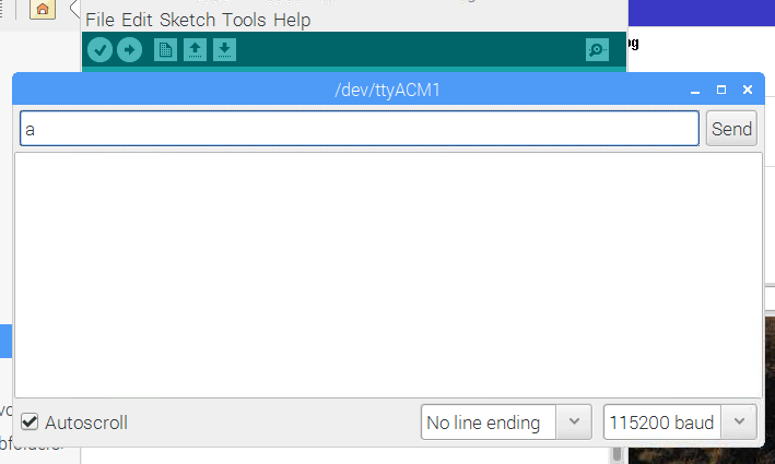
if you open the serial monitor in the Arduino IDE
![]()
you can test the camera mount sending the characters a, d, w, s
    w
  a ☩ d
    s
and taking a few pictures typing
raspistill -v -o test.jpg
in the terminal as we learned in the last project.
Next: The target
-
3The Target
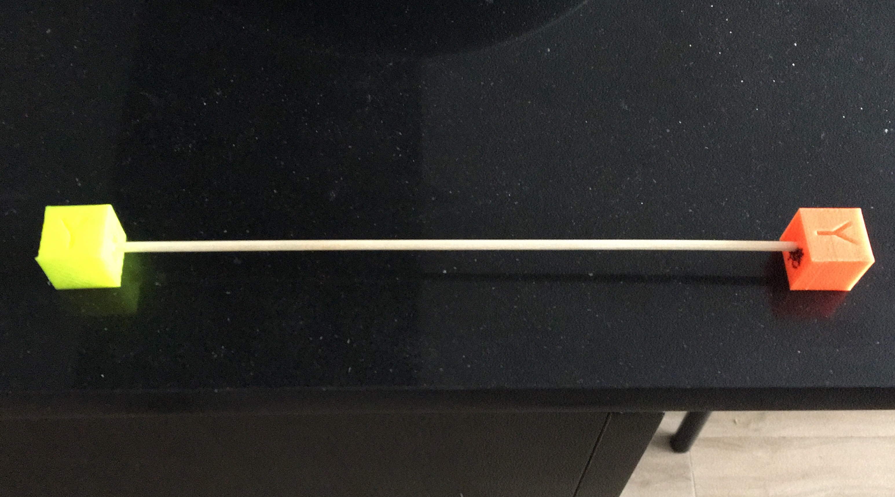
for the target i used a few cubes for testing calibration of 3D printers that i grabbed from the recycle bin and a skewer with a few drops of instant adhesive.
![]()
you can use a small ball or a few lego cubes. the point is to try to have something that could be easy to recognize from the background...
![]()
yeah, you understand ;)
Next and final step: Control everything from Mathematica!
-
4Control everything from Mathematica
Now it's time to track!
First a few words on te arduino code:
the arduino is listening to the serial port (in this case the usb cable from the pi provides power and serial to the arduino). when it receives one of the commands its moves the servo to the new position. is very simple, as we say before you can test it from the serial monitor in the arduino IDE.
this is the control code on the mathematica side:
centro = {300, 200};
serial = DeviceOpen[ "Serial", {"/dev/ttyACM1", "BaudRate" -> 115200}];
Pause[2]
DeviceWriteBuffer[serial, "c"];
img = Import["!raspistill -n -w 600 -h 400 -t 1 -o -", "JPG"];
avgpv = Mean[PixelValuePositions[img, Red, .3]];
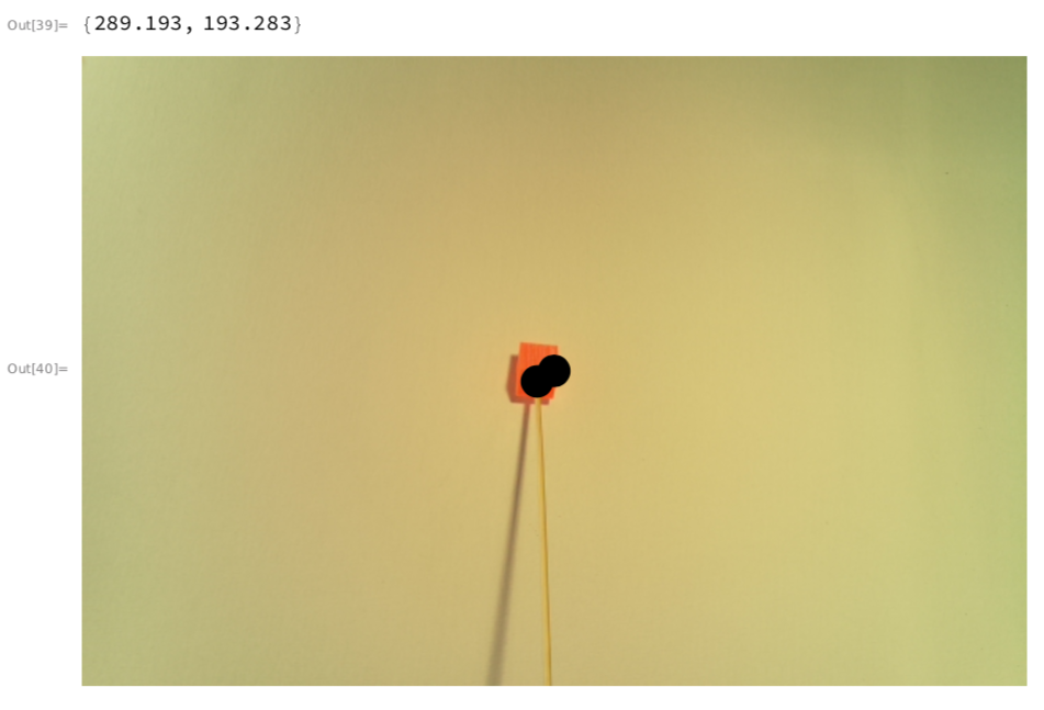
N[avgpv]
HighlightImage[img, {avgpv, centro}, "HighlightColor" -> Black , Method -> {"DiskMarkers", 20}]
Do[
imgVarX = Import["!raspistill -n -w 600 -h 400 -t 1 -o -", "JPG"];
avgpvVarX = Mean[PixelValuePositions[imgVarX, Red, .3]];
displaceX = 300 - Part[avgpvVarX, 1];
If[displaceX > 0, DeviceWriteBuffer[serial, "a"];,
DeviceWriteBuffer[serial, "d"];];
, 25]
Do[
imgVarY = Import["!raspistill -n -w 600 -h 400 -t 1 -o -", "JPG"];
avgpvVarY = Mean[PixelValuePositions[imgVarY, Red, .3]];
displaceY = 200 - Part[avgpvVarY, 2];
If[displaceY > 0, DeviceWriteBuffer[serial, "w"];,
DeviceWriteBuffer[serial, "s"];];
, 15]
imgFin = Import["!raspistill -n -w 600 -h 400 -t 1 -o -", "JPG"];
avgpvFin = Mean[PixelValuePositions[imgFin, Red, .3]];
N[avgpvFin]
HighlightImage[imgFin, {avgpvFin, centro}, "HighlightColor" -> Black , Method -> {"DiskMarkers", 20}]it's a little more complex since the last time, but let's check it step by step:
centro = {300, 200};
creates a variable for the center of a 600x400 image
serial = DeviceOpen[ "Serial", {"/dev/ttyACM1", "BaudRate" -> 115200}];
Pause[2]
DeviceWriteBuffer[serial, "c"];Opens the serial port in 115200 baudrate in the /dev/ttyACM1 port. You can get the port from the arduino IDE (in windows they take a name like COM3). then pause for 2 seconds to let the serial port get ready and send the command "c" that resets the camera mount to get the camera ready to start.
img = Import["!raspistill -n -w 600 -h 400 -t 1 -o -", "JPG"];
we take a picture and store in img
avgpv = Mean[PixelValuePositions[img, Red, .3]];
N[avgpv]then calculate the average (more or less center) of the coordinates of all the pixels with a value of Red higher than 0.3 (remember the target? my target is bright orange. You can test and fit it to your needs changing the color and the threshold value). the next line prints to the notebook a numerical representation of the coordinates of the target as debug.
HighlightImage[img, {avgpv, centro}, "HighlightColor" -> Black , Method -> {"DiskMarkers", 20}]
Then we create an output to show the picture with the center and the target identified with a black point
![]()
Next we have two very similar cycles to control the camera mount and center the target in the camera:
Do[
imgVarX = Import["!raspistill -n -w 600 -h 400 -t 1 -o -", "JPG"];
avgpvVarX = Mean[PixelValuePositions[imgVarX, Red, .3]];
displaceX = 300 - Part[avgpvVarX, 1];
If[displaceX > 0, DeviceWriteBuffer[serial, "a"];,
DeviceWriteBuffer[serial, "d"];];
, 25]
Do[
imgVarY = Import["!raspistill -n -w 600 -h 400 -t 1 -o -", "JPG"];
avgpvVarY = Mean[PixelValuePositions[imgVarY, Red, .3]];
displaceY = 200 - Part[avgpvVarY, 2];
If[displaceY > 0, DeviceWriteBuffer[serial, "w"];,
DeviceWriteBuffer[serial, "s"];];
, 15]the first one is for track in the horizontal axis (X) and the second for the vertical axis (Y).
First we take a picture and detect the target coordinates, then calculate the X axis displacement. if we need to move the camera to the left we send an "a" and otherwise a "d". The second one does the same but using "w" and "s" to move up and down.
We repeat this 25 times for the X axis and 15 for the Y because we have a 600x400 picture. you can try with a while or and if cycle if you wanna optimize the speed of execution.
after this two cycles we should have the target centered in the camera.
imgFin = Import["!raspistill -n -w 600 -h 400 -t 1 -o -", "JPG"];
avgpvFin = Mean[PixelValuePositions[imgFin, Red, .3]];
N[avgpvFin]
HighlightImage[imgFin, {avgpvFin, centro}, "HighlightColor" -> Black , Method -> {"DiskMarkers", 20}]then, same as in the beginning, we take a picture and mark the target and the center with spots and output the numerical coordinates for debug.
![]()
yeah! we are tracking or target now! =D
here we have a 30 secs video of the project working with a laser diode to show the original position of the camera (a laser spot on the left on the first seconds) then move the camera to center and then shot a few lasers to mark the target.
Greetings!
Raspberry+Arduino CamTracker
Easy and Fun: Track objects with a Raspberry Pi, a camera and an Arduino in less than an hour!


Discussions
Become a Hackaday.io Member
Create an account to leave a comment. Already have an account? Log In.
I was going to use this project in my war machine inspried nerf armor on my profile.
Are you sure? yes | no