 Steve
Steve-
1Design Details
Here are some details about the clock design and gear ratios used. Let's start with the naming convention used when designing the clock. There are eight gear sets labeled mostly starting with the escapement labeled as gear 1. I suppose the pallet could have been called gear 0, but I simply call it the pallet. The rest of the gears are labeled sequentially towards the weight drum.
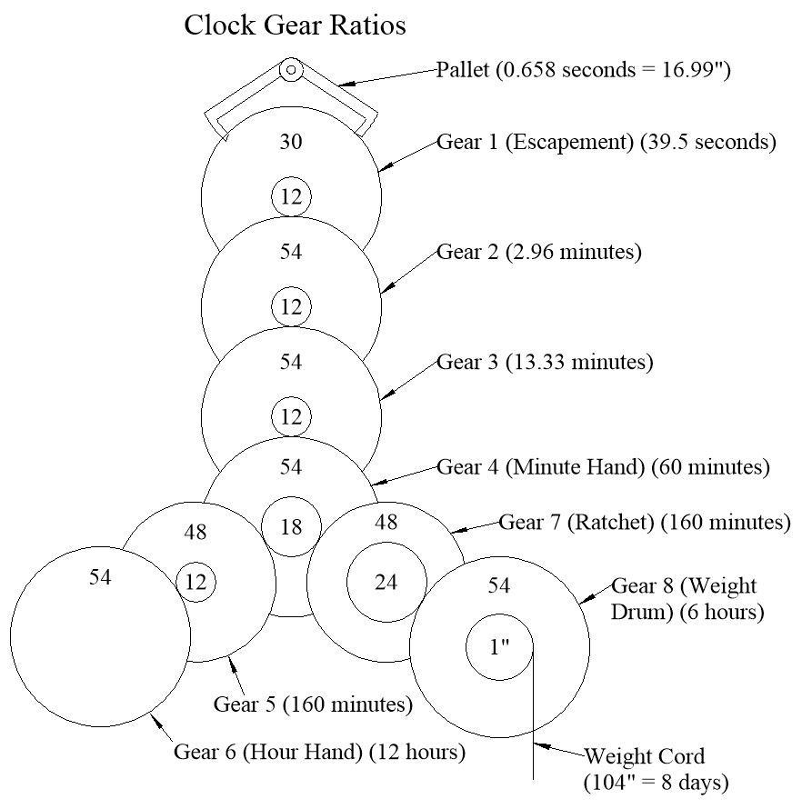
Here is a diagram showing the clock gear connectivity and speed. The weight shell has a pulley, so a 52" drop unwinds 104" of cord. Gear 8 rotates once every 6 hours. Each gear in the train rotates slightly faster, until it gets to the escapement rotating every 39.5 seconds. Gear 5 and 6 form a secondary path for the minute hand to drive the hour hand. There are two 18 tooth pinions on gear 4 with a friction fit to allow setting the time.
![]()
The gear thicknesses and clearances were defined using the following mockup. Most gears are 0.2" thick. Gears 7 and 8 have the most weight on them, so they were made thicker. There are two 608 skateboard bearings supporting the weight of gear 8. The escapement and pallet were also made slightly thicker to provide a larger wear surface. The pallet has tiny ball bearings to support the weight of the pendulum. I experimented with several different sized bearings and picked a size that allowed a pendulum to "free swing" the longest. The load is significantly below their design limit so I am expecting them to last a long time.
![]()
-
2Power Gear Assembly
This section shows the process of assembling the gears into the frame. There are a few preparation steps that need to be completed before assembly. For now I will just leave it as "print everything and cut the axles to length". More details to will be added later.
The build in the next few sections shows a rough rendering of the clock in 3D form. One of my long term goals is to learn photo-realistic rendering in TurboCAD to make the diagrams even better.
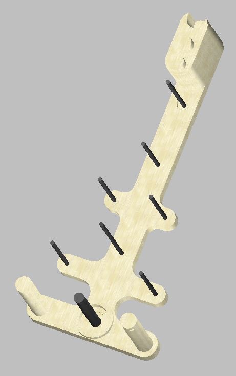
Start with the back frame. The standoffs and keyhole hanger should be attached to the back of the frame as the first step. The picture below shows all of the axles in place, although they will get placed as each gear get added. The standoffs are not shown, but they would position the frame 1" away from the wall to provide clearance for the pendulum.
![]()
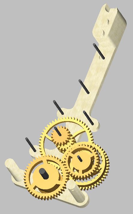
The gears should be assembled starting from the bottom gear to the highest to allow clearance. Gear 4 with two 18 tooth pinions is the first one, followed by the ratchets, and the weight drum (after inserting a 608 bearing into the pocket).
![]()
Oops, I just realized that the image above shows the 4-day weight train with a 44:34 gear ratio and a 1.1" winding drum. After fine tuning the design, I was able to switch the gears to a 54:24 gear ratio and a 1" winding drum to provide an 8 day run time. Swapping out the two gears is all that is needed to switch between modes. The assembly instructions are the same.
-
3Escapement Assembly
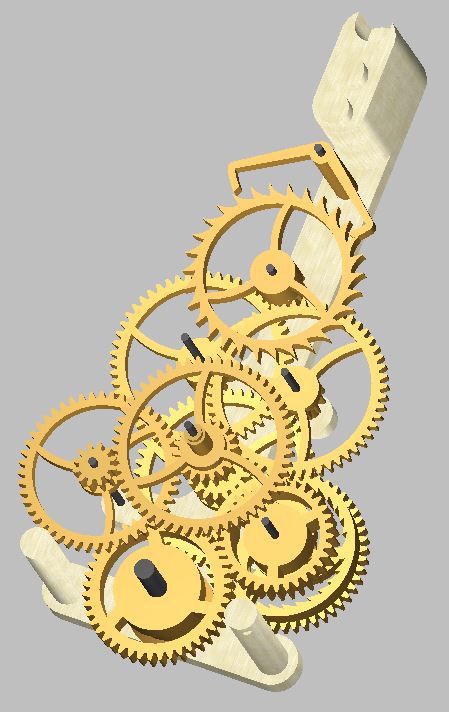
The next step is to work towards the escapement. Add gear 3, gear 2, the escapement, and the pallet. The pallet shaft sticks out the back of the frame to attach the pendulum. It also has two 1/8x3/8x5/32 bearings.
![]()
-
4Hour Hand Gears and Front Frame
The final gears to insert are gear 5, and gear 6 for the hour hand. The image below shows all the gears positioned into the back frame.
![]()
The front frame needs the bearing holder with 608 bearing and crank handle hanger added using 6x3/4" wood screws. The screws are hidden behind the frame, so they need to be assembled first. Attaching the front frame is a bit tedious, since 4 support posts and 8 axles all need to be lined up. I have probably assembled and dis-assembled my clock at least 50 times while fine tuning different parts. It is still tedious. My only advice is to be patient at this step.
Start in one corner and work towards the top. The two halves will go together part way, then stop on a pinched axle. Move the pinched axle and the frame should close a bit more until the next axle is pinched. Hold the starting corner closed while working to keep then from separating back apart. Keep moving them into position until the frame comes together.
![]()
The frame is held together by three 6x3/4" wood screws, two at the bottom and one from the top. Add the hands. The hour hand is a loose fit and can be positioned anywhere. The minute hand has a flat to keep it tight when changing the time. The axle on gear 4 has a friction fit to slip when changing the time.
3D Printed Pendulum Clock
A 3D printed clock in PLA. It has an 8 day runtime with an accuracy of 1-2 minutes per week.


Discussions
Become a Hackaday.io Member
Create an account to leave a comment. Already have an account? Log In.