Stephen Holdaway
-
Still room for improvement
08/07/2021 at 05:07 • 0 commentsAfter honing the precision of the Tiny GPS Clock, I'd like to improve the GPS Wall Clock in the same way: using the GPS module's timepulse (1PPS) signal to synchronise display updates precisely with the top of each second.
There's a couple of small problems however:
- There are exactly four bytes of program space left on the ATTiny13a's 1KB flash.
- All of the microcontroller's pins are in use.

This seems like an interesting challenge. Let's see how far we can get.
Digging for more program space
Going into probably the fifth or sixth code size reduction pass on this project, I really wasn't sure how much more could be done. Surprisingly, in a few evenings chipping away at the problem I managed to free up 180 bytes (17.5% of the total program space) without removing any functionality. Most of this was achieved by giving the compiler as much as possible to work on at once, with a sprinkling of other small optimisations:
Compiled as a single unit to maximise the compiler's ability to optimise - ie. including source files rather than headers in
main.c. This is a little messy as it breaks the encapsulation allowed by separately compiled source files, but this alone saved 84 bytes of program space, so it was worth the trade-off for this project (commit).Used
-nostartfilesand provided a custom assembly entry point. This allows some redundant instructions GCC adds for software reset and "exit" to be removed, but most importantly lets us store code in the space normally reserved for the interrupt vector table, since interrupts aren't used at all. Freed up 24 bytes (commit).The assembly portion (startup.S) is fairly straight forward as all it needs to do is zero out memory and jump to
main(). All variables in the C program are already initialised to zero to avoid the need for additional memory initialisation on reset.Replaced
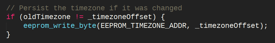
eeprom_read_byteandeeprom_write_bytecalls fromavr/eeprom.hwith C source implementations from the datasheet. Having these functions in-source allows inlining as they're only used once each, plus they could be slightly modified to strip out a wait loop that's irrelevant in this application. Freed up 36 bytes (commit).Replaced two calls to
spi_sendwith a single call where the address and data bytes to send are combined as a single 16-bit value. Combining these bytes takes the same number of instructions as making two function calls, but with only one function call the compiler can inline the function. Freed up 8 bytes (commit).Replaced multiply by 10 with bit shifts equivalent to
(x*8) + (x*2). There's no other multiplication in the code that uses non-power-of-two factors (that get compiled to bit shifts), so there's no need for a generic multiply routine. Freed up 6 bytes (commit).
Some of these wins involved disassembling the firmware using
avr-objdumpto spot where space was being wasted:
I initially looked into using a custom linker script, but using
-nostartfilesended up being a much cleaner solution. Labels in the disassembly like__trampolines_endand__ctors_endwere a bit misleading - marking the end of sections which were actually empty and not relevant at all.I wanted to keep this as accessible and easy to work on as possible, so going to hand-written assembly wasn't really something I wanted to do outside of the short startup file. The compiler now optimises 90% of the code into a single function, which would be painful level of optimisation to achieve and maintain by hand.
Avoiding interrupts
Performing an action on a rising edge seems like a great case for interrupts, but given the code space constraints on this chip, it's not really practical. An interrupt handler doing anything more than flipping bits in register memory will need to push and pop registers to the stack, which quickly eats up program space at 4 bytes per register used, plus the instructions to do the required work.
It ends up being more practical space-wise to avoid interrupts and just carefully structure the main loop to get the required behaviour and timing.
Abusing unused register (I/O) memory
The lowest 32 bytes of memory on the ATTiny13a are bit-addressable, which means single-instructions can be used to read, write and test bits instead of using multiple instructions like the regular memory requires:
; Set bit 1 at address 0x05 (PORTB) - I/O memory
sbi    0x05, 1

; Set bit 1 at address 0x9F (bottom of SRAM)
lds    r24, 0x9F ; Load current memory value into register
ori    r24, 0x02 ; Set bit 1
sts    0x9F, r24 ; Store result back in memory
Most of the I/O memory space is used by important working and control registers, but with some careful analysis it's often possible to find individual bits that won't affect behaviour and can be repurposed. In this case I've repurposed:
- PB5 bit of DDRB: with the fuses set to use the RESET pin as reset, the port and direction registers for PB5 have no effect.
- AIN0D bit of the DIDR0 register: The "input buffer disable register" for PB0 has no effect as this pin is always an output in this application.
Saving one boolean in memory might not seem like much, but the saving on code space with fewer required instructions adds up once you write, read and test the value in a few places.
Double duty GPIO
So there's space to add more code, but we still need to figure out if it's possible to get the timepulse signal from the GPS into the existing circuit. I started by analysing the pin assignments on the ATTiny:
- PB0: MOSI Data output to the MAX7219. Available when not sending data to the display.
- PB1: SOFT_UART/MISO UART input from GPS, which is externally switched to MISO for in-circuit programming. This is the INT0 interrupt pin which would be potentially useful for the timepulse, but I don't really want to change pin assignments around so will leave this alone.
- PB2: SCK Clock output to the MAX7219. Available when not sending data to the display.
- PB3: LOAD_CS Chip select for the MAX7219. Idles high when not sending data to the display.
- PB4: LIGHT_SENSE/BTN Analog input that's already serving multiple purposes. Mixing an additional digital signal in here would be messy, so I'll leave it alone.
- PB5: RESET This pin can't be used as I/O without disabling in-circuit programming. Using high-voltage programming would be impractical for this device given the existing circuit, so this pin needs to remain as reset.
That leaves PB0, PB2 and PB3 as potential inputs. The timepulse signal can't be connected directly to any of these without affecting their output voltage, since the timepulse idles low - sinking to ground. However, if we use the timepulse signal to switch a pull-down resistor instead, it's possible to sneak our input signal in without affecting that pin's output capability. This pull-down resistor only needs to be strong enough to overcome the weak internal input pull-up in the microcontroller.
I opted to attach timepulse to the LOAD_CS pin, since its high output state can be switched to input-with pull-up in a single instruction. A couple of resistors and an NPN transistor are used to create a pull-down from the timepulse signal:

Conveniently, the 0805 LED and resistor on my GPS module's timepulse pin could be removed and replaced with some of these components. It doesn't all fit, but the existing pads made this easier than soldering everything as a floating bodge:

Pull-down resistor sizing
The resistor between the transistor's collector and LOAD_CS is needed to prevent the microcontroller pin sourcing too much current when configured as an output while timepulse is active. This resistor could be avoided if there was coordination to ensure timepulse is never active when LOAD_CS is an output, but there's no reason to go to that effort here.
I initially pulled down through a 1.8K Ω resistor which worked fine, but it did result in a very slow falling edge:

Reducing the pull-down resistance to 470 Ω speeds the edge significantly, though causes a current of 10mA flows while timepulse is active if LOAD_CS is an output:

10mA from an I/O pin is well within the spec of the microcontroller, but it's a bit of a waste of power. The waste could be reduced by changing the timepulse length from its default of 10 milliseconds to something like 10μS.
Buffering the time to display
With the timepulse signal finally coming into the microcontroller, the firmware needed some modifications to tick accurately. The gritty details of this are covered in the Ticking Accurately with the NEO-6M write-up, so I won't repeat them here, but the important changes were:
- Added a 6-byte buffer to hold the display data ready for immediate output at the top of the second. This wasn't strictly necessary, but it aligns with the implementation in Tiny GPS Clock.
- Added code to increment time for display at the next timepulse
- Shuffled the main loop around with a blocking wait for timepulse or UART transmission (which ever comes first), and a check if the timepulse fired.
- Added detection of the timepulse not firing and fall back to the original direct-from-UART time display method. The last decimal point is illuminated if this fall back is active.
After these changes, the program is back up to 1006 bytes (18 bytes free). Ready for the optimisation again next time I want to add a feature!

The far-right decimal point is now lit when the displayed time isn't synced to timepulse. In this state the time continues to update using the original, less accurate method. Calibrating the timepulse
With the timepulse coming into the microcontroller and code changes made, the last step is offsetting the timepulse to account for the display update time:

As there's not enough program space left to send configuration commands to the GPS module from the microcontroller, I used the u-blox software u-centre to modify the configuration on the clock's GPS module and save it its SPI flash, without writing any code. This software is only available for Windows, but it can be run in a virtual machine without issues.
Setting the User Delay option of the timepulse to 154μS accounts for the time it takes to update the display's digit memory. With this set, the timepulse fires slightly early to account the delay between the rising timepulse edge and the display completing its update.
Until next time...
I can finally rest easy knowing this source of time in our apartment is slightly closer to the arbitrary concept of time we've invented, even if I have no way to absolutely measure it. The difference is ultimately unnoticeable, but it is nice to see the various GPS clocks in our apartment tick in synchrony now:
-
Squeezing in timezone persistence
02/15/2020 at 11:00 • 0 commentsFor most of the last 9 months, I've successfully avoided unplugging this clock. It's something I've specifically avoided as every power cycle requires pulling the clock off the wall, holding the timezone button for 5 seconds and then remounting on the wall. This is not a terrible burden by any measure, but apparently it's enough of an annoyance to warrant spending multiple hours updating the firmware.
![]()
Storing a single byte in eeprom on an AVR is straight forward - a call to eeprom_write_byte here, a call to eeprom_read_byte there. The challenge for this project is fitting another 72 bytes of code into the remaining 30 bytes of the ATtiny13a's flash space!
Having already made multiple size-reducing passes on this code previously, I wasn't hopeful that significant savings could be made. Minor tweaks could be made, but It would be a mission to find 42 bytes worth of those. Thankfully I managed to extract the required space with just two changes (commit):
- 30 bytes: Consolidated three places where digits were selectively blanked into a common "clear display" function
- 14 bytes: Dropped the unused day, month and year fields from the NMEA string parsing
With space freed up, the eeprom save/restore was an easy add (commit). Hopefully no further additions are needed as there's just two bytes of code space free.
Edit: I noticed a stupid late-night bug immediately after posting this which required freeing a further 8 bytes (commit)! The code usage is now exactly 100% at 1024 bytes.
-
Maintenance and improvements
05/18/2019 at 22:51 • 0 comments
As winter approaches here in the southern hemisphere, the wire-wrapping from the original build of this display is proving to be be a bit unreliable. Without proper wire-wrap pins and the right tool, there's just not enough force to stop connections coming loose. The effectiveness of percussive maintenance has been dwindling, so it's time to for some upgrades.
Better display connections
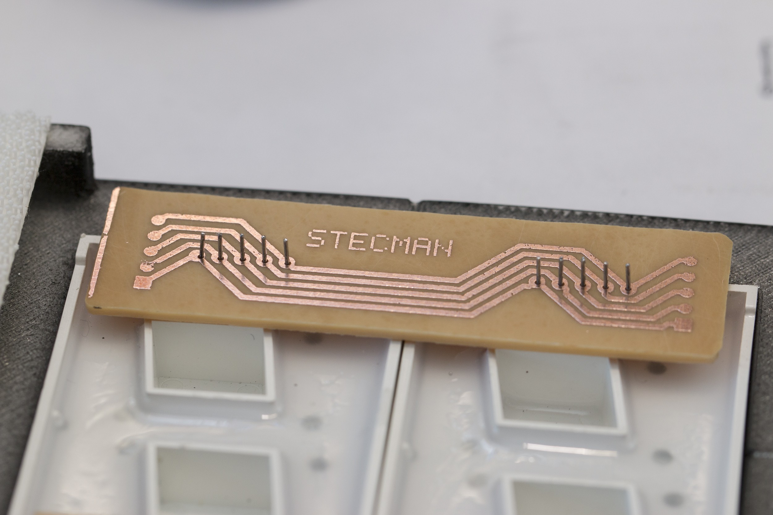
I thought about simply adding solder to the wire-wrap joints to make them more robust, but the mess of overlapping wires meant I was likely to melt some insulation and short pins out. Instead I figured I'd completely replace the point-to-point wiring with some PCBs to make it tidier and stronger.
After a few iterations of layout, I ended up with two small boards to attach to each pair of digits that connect all of the segments:

I needed this fixed over the weekend, so the layout was designed for etching my own PCBs instead of ordering them. Ideally this would've been one long board to connect all digits, but the equipment I have makes it impractical to make a board larger than about 100mm square.
These are fiddly to make, but they turned out ok:

![]()
Once constructed, the 6 boards were soldered into place and wired together with 0.5mm (22 AWG) solid copper wire. 16 wires was far more manageable than the 40 point-to-point connections when I wire-wrapped these originally:

Once the driver was wired back in, I was pleased to find I hadn't made any mistakes or shorted or broken anything. The original build had the digits wired backwards which I'd neglected to fix in hardware at the time and was managing in my local copy of the code:

The time is backwards but otherwise correct. With sturdy new connections, the clock should hopefully be maintenance-free for quite some time.
As a finishing touch I added a 50uF electrolytic capacitor to the board to stop the ceramic caps whining when the display is being driven at a high brightness. This wasn't audible originally and I'm not sure why it's occurring after 3 months of use, but the extra cap has completely silenced it.
Firmware improvements
Over the last couple of months we've seen an unexpected timezone increment a number of times - usually by one or two steps, and usually overnight or when the house was dark in the evening.
The most likely suspect was the shared ADC reading for the light sensor and timezone change button that only required a single sample below a set threshold to increment the timezone. I've changed this to require 5 readings 100ms apart before the timezone will be incremented (fix), putting the existing 500ms delay to use.
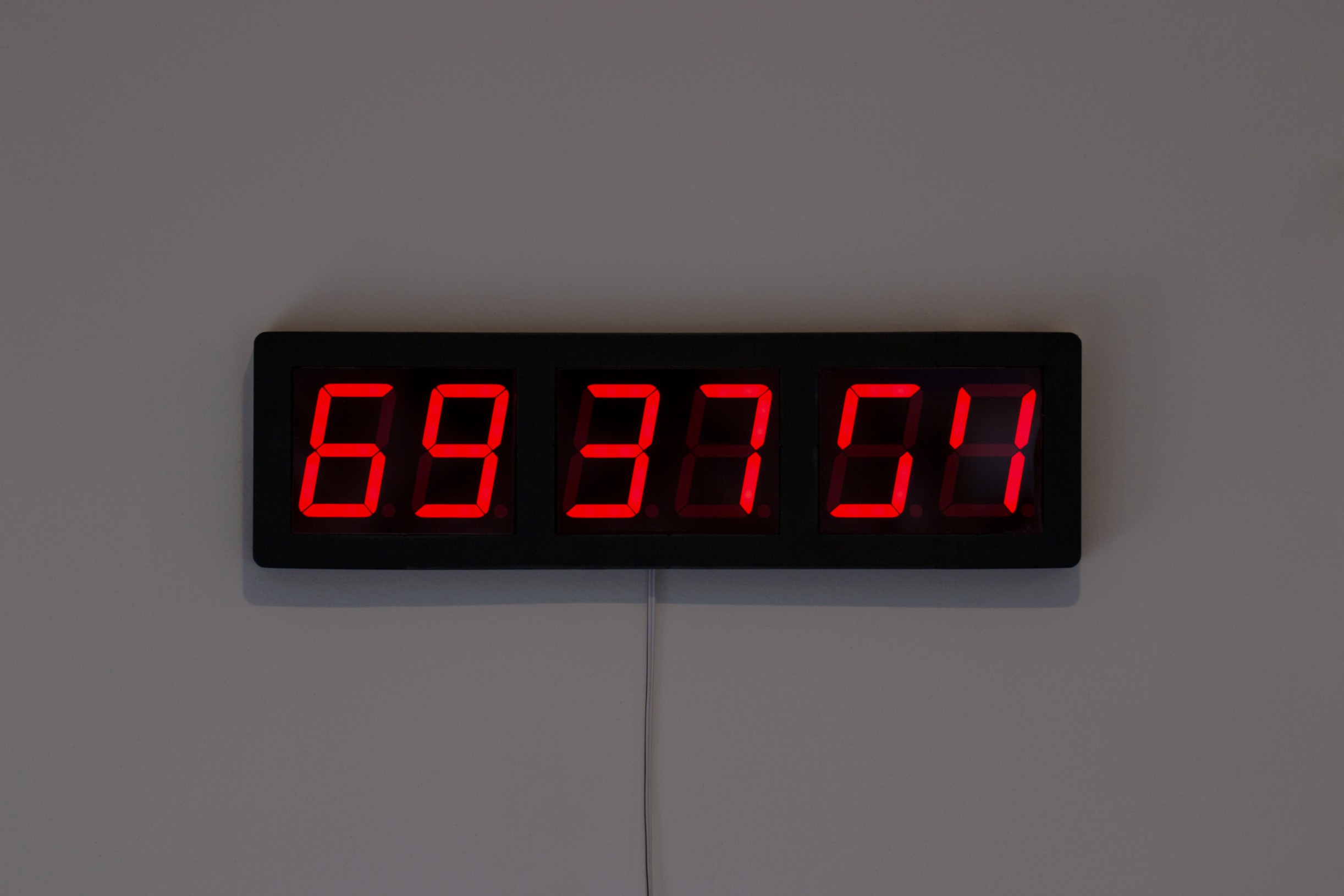
The uncommanded timezone increments also revealed a bug where a negative value for hours wasn't being wrapped (fix). This resulted in some mild entertainment:
![]()
The fun thing here is that the hour is correct in the one's column when the timezone is set to -12 due to the way the math works out:
# Unsigned addition of -12 offset to UTC hour "09"
9 + -12 = 253

# Reduced by 24 as the value is greater than 23
# This makes the ones column match the UTC hour
253 - 24 = 229
The "6" comes from the MAX7219's interpretation of the tens value:
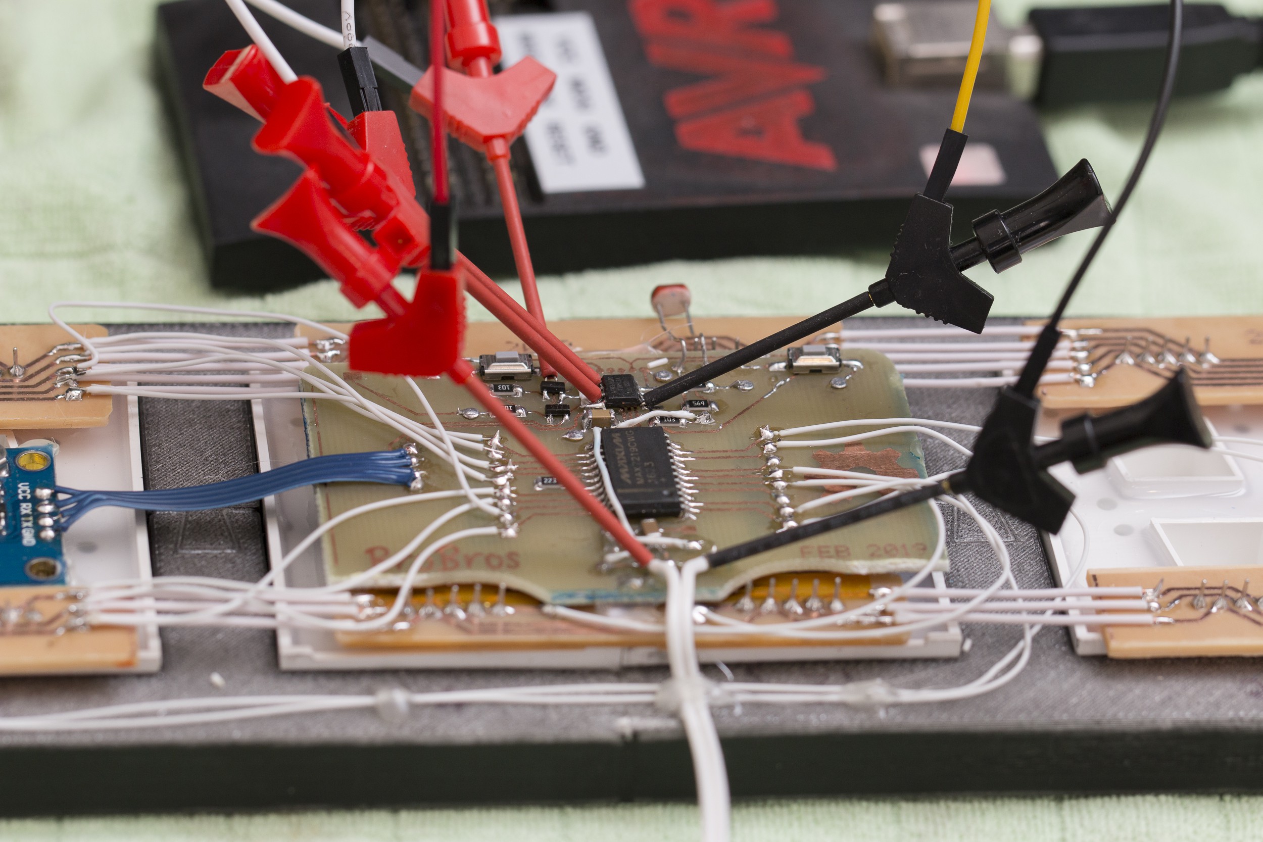
# The number of tens is calculated
229 / 10 = 22

# Displayed as "6" because the MAX7219 ignores the high nibble
22 & 0x0F = 6
I made these fixes a few weeks ago, but I'd been putting off updating the firmware for this as it's a bit of a pig to program: the footprint for the programming header is the wrong pitch, so instead of using a pogo-pin jig as intended, each connection has to be made manually with test clips:
![]()
The digit order needed to be corrected before the display could be used again, giving a chance to push these fixes at the same time. As a bonus, I no longer have to maintain a digit-reversed version of the code while keeping the code in the correct wiring on GitHub!