-
upgrading
10/26/2016 at 22:23 • 0 commentsI want to do it the current way. That is, feed a gate of MOSFET with known current rather than known voltage. I also want to experiment with positive vs negative voltages.
So, I'm building a brand new "experimentorture" circuit! It is going to feature a precision automated gate threshold voltage measurement, potentially with datalogging.
The problem is, I'm out of relays that my signal gen can drive. But, I recalled I bought a photovoltaic optocoulper thingy VO1263 quite some while ago, and it is a perfect opportunity to try it out. It allows me to connect a mosfet (or a pair) to create a solid state relay. And it has two channels! Now I can short tortured transistor's drain to source during torture. I expect that to have a little bit of an effect on the quality of the resulting hacked transistor.
I don't dismantle the old blink torture circuit yet, it will come in handy for measuring transfer characteristics.
--------
I also wonder, what will happen if I torture a p-channel mosfet. I would bet, in contrast to n-channel, its gate threshold voltage will increase in magnitude. That is, the biasing will go the same way exactly like it does for n-channel ones. So, I think I will not be able to drive a p-channel mosfet into depletion. Only one way to find out...
-
Doodling in search for explanation
10/24/2016 at 14:31 • 0 commentsObservations to explain:
* applying large negative voltage to gate => lowering threshold
* applying large positive voltage to gate => lowering threshold
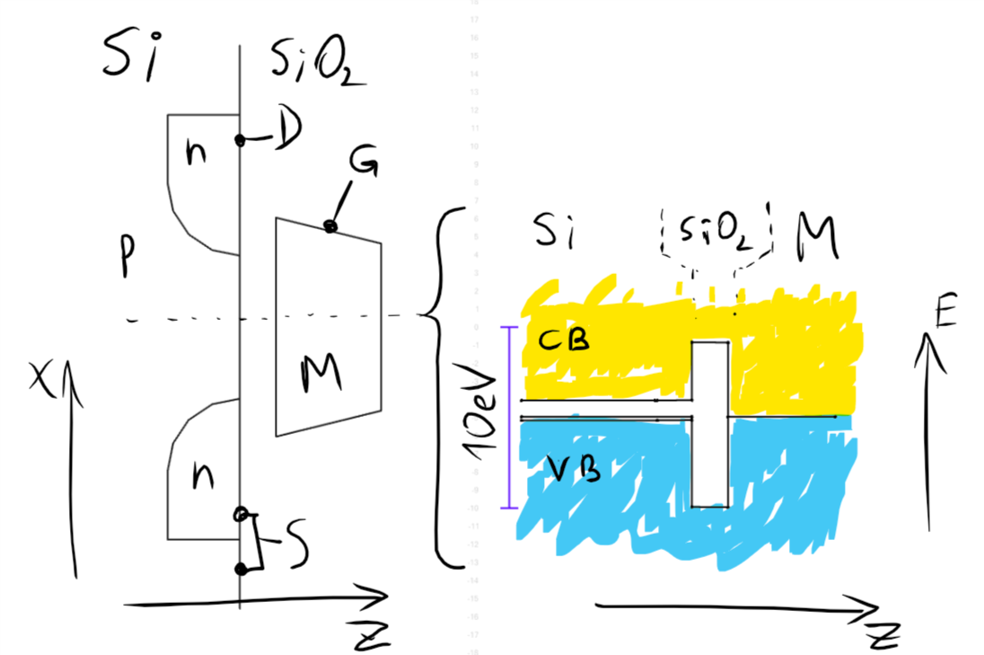
First, a painting of mosfet with no voltages applied.
![]() On the left, cross-section of the device is shown (n-channel MOSFET). Dashed line is a cross section for which band diagram is drawn.
On the left, cross-section of the device is shown (n-channel MOSFET). Dashed line is a cross section for which band diagram is drawn.On the right, I painted a band diagram along a section line. I have taken band positions from this page:
http://www.nextnano.com/nextnano3/tutorial/1Dtutorial_pSi_SiO2_polySi.htm
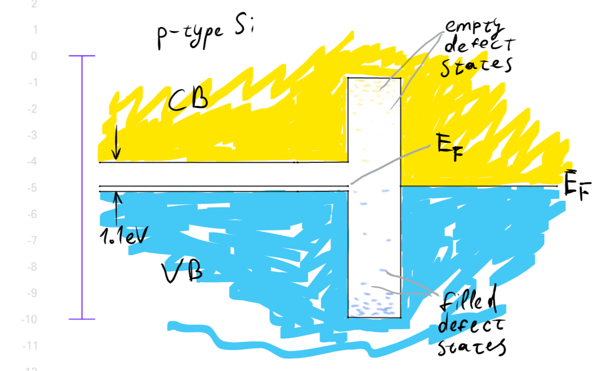
Yellow fill is empty electron states. Blue fill is filled electron states. White area is forbidden zone (bandgap). Horizontal line in the middle is Fermi energy, in this case equal for both sides, as there is no voltage applied.
There might be built-in field because of difference in work functions between base material and gate material, but I just assume they are equal, for simplicity.
![]()
Closeup of the band diagram. Defect states in SiO2 are shown.
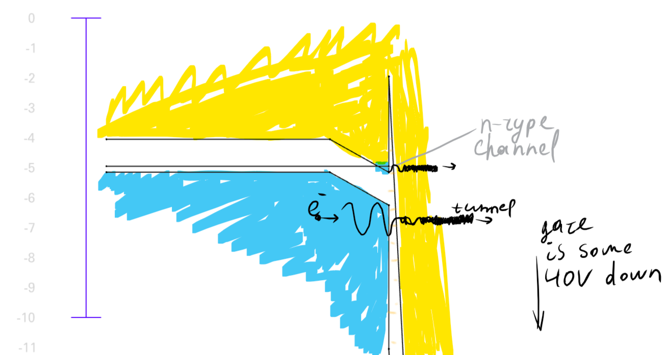
Now, here comes the diagram for transistor under torture.
![]()
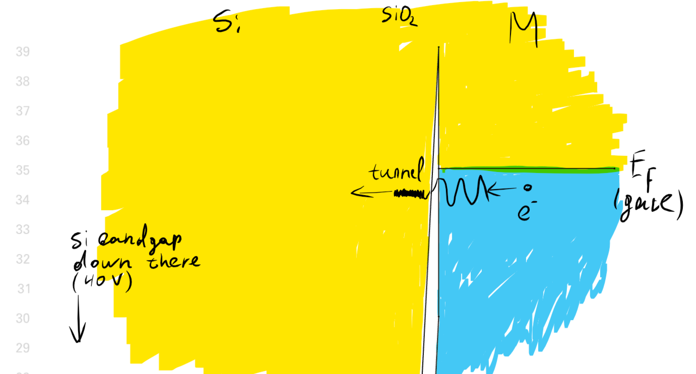
... up at the Si side... and ... down at the gate side...
![]()
That was for positive voltage (40 V) applied to gate.
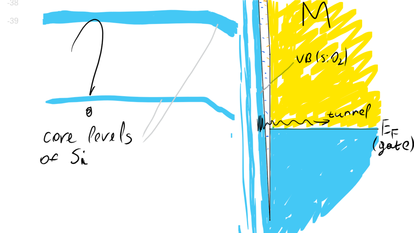
Now, for negative:
![]()
... up at the gate side... and ... down at Si side....
![]()
These were drawn with no explanation of the mechanism. These pictures are pretty general, and I hope there isn't much that I could get terribly wrong here.
... more to come...
-
positive torture voltage
10/23/2016 at 20:11 • 0 commentsI expected that by applying large positive voltage to gate, I would increase gate threshold voltage. But as @RoGeorge accidentally found in #Your MOSFET is not good enough? Then modify it!, positive torture voltage leads to the same direction of gate threshold voltage change. IT GOES DOWN! And I can confirm it!
Does it make any sense to you?
-42V ->Vgt decreases
+42V -> Vgt decreases
whaaat??!
-----------
Because the effect is very sensitive to the voltage (39 V -> it takes hours, 42V -> seconds), and because in positive torture voltage I can't monitor transistor shifting in real time with my blink torture circuit, I decided to go for current-mode torturing. From how brightly the LEDs in series with torture voltage source lighted up, I deduced the gate current was about 2 uA when I applied -42 V. So, for positive voltage torture, I connected torture voltage source through a 10M resistor, and cranked it up to 60 V. Works!
This leads me to another experiment. Maybe a current mode torture is going to be more linear. That's what I'm up to now, with the only problem that I don't have a controllable microamp-range current source. So I'll need to build one first.
One of my multimeters can measure down to 0.01 microamps, so seems like a 10M resistor in series with adjustable voltage power supply will do. I have to think about it a bit.
-
testing tolerance to switching drive
10/22/2016 at 11:06 • 2 comments@RoGeorge asked, if the conversion is permanent, in particular to regular signals applied to gate. This what I'm testing.
First, I measured gate voltage for 1 mA drain current as precisely as I can. => -1.194 V.
Now, I've connected a signal generator across source-gate, and left the drain floating.
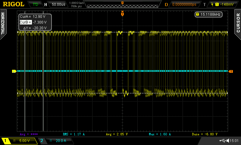
Signal generator is set up for generating square wave from -7.3 V to +12.9 V, with peak-to-peak voltage of 20.2 V. This is the maximum amplitude my signal generator is capable of.
![]()
The frequency of the square wave is swept from 100Hz to 1MHz in a logarithmic manner, with a period of 1 second.
In 10 or so hours, I'll stop the generator and re-measure the mosfet.
...
12 hours later:
Vg(Ids = 1mA) = -1.123 V (was -1.194)
So, the depletion mode was reduced by a little bit. The change is certainly above precision of my measurement, and it's not due to mosfet temperature during Vg measurement. But as for if it was actually caused by the gate waveform exposure, or it was just natural decay of the biasing - I don't know. I didn't do a control experiment. In any case, more testing is needed.
...
26 hours later:
the mosfet was doing nothing at all for 14 hours. I remeasured the gate voltage needed to conduct 1 mA, and it is now -1.094 V. So, it becomes quite obvious that waveform applied to gate has probably nothing to do with the observed change. It is just transistor slowly drifting back towards its factory state.
-
Potential applications of depletion mode MOSFETS
10/21/2016 at 21:43 • 0 commentsHere is a simple adjustable brightness flashlight circuit. This is the main thing I want depletion mosfets for!
Apart from being simple, the circuit has a few practical features.
* Continuous brightness adjustment flashlights are quite rare.
* Flicker-free. Important for video/photography.
* This circuit allows to adjust the brightness in extremely wide dynamic range, from totally off to barely visible in complete darkness to full power the LED can handle.
* The input current required by mosfet gate is negligible, which makes it possible to put very large resistance potentiometer. Dodgy viper contact isn't going to cause any issues.
* There is no need for on/off switch - the adjustment pot does it. The off current can be made as low as desirable by increasing potentiometer resistance, and can possibly be even made negligible compared to self-discharge due to cell protection circuitry.
The main disadvantage of this circuit is that it's relatively inefficient, although I think this is easily compensated for by lowering brightness as needed.
--------------------
more potential applications:
low or negative voltage drop voltage follower
-> LED brightness control (as just shown)-> LDO regulators
-> amplifier output stage (rail-to-rail with no bootstrap)inrush current limiter
-> DC
-> AC -
Transfer characteristic
10/19/2016 at 19:10 • 0 comments(UPDATE: more data added to plot)
Measured one!
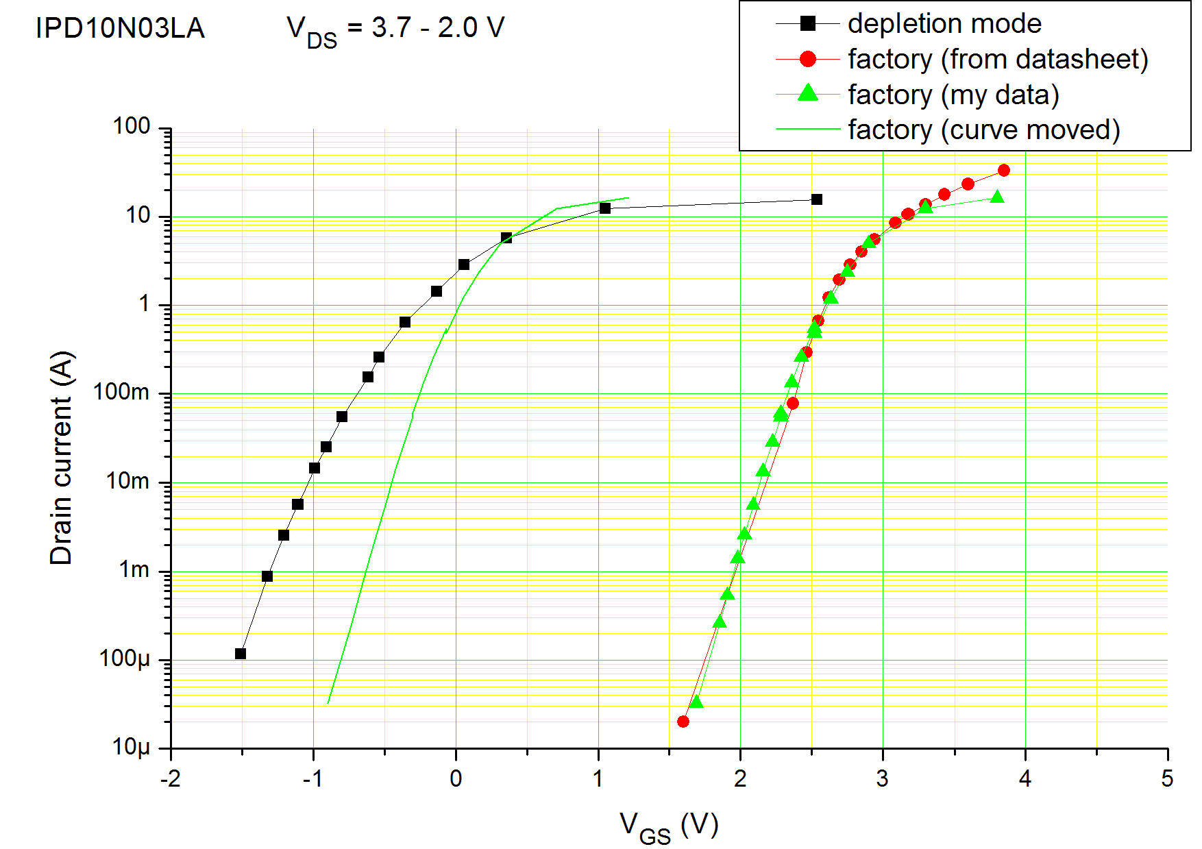
On the left is the transfer characteristic I measured for my MOSFET that I converted to depletion mode. On the right, I plotted the characteristic from datasheet, and my own measurement of a fresh MOSFET. They depart a little bit in high current range, because my measurement setup is not capable of currents above 10 A (Li-ion cell can't provide much more than 10 A).
The characteristic is not too bad, but it does have a noticeably lower slope than the datasheet one (to make it more obvious, I placed a replica of factory state curve close to the hacked depletion mode curve).
-
Depletion mode achieved!
10/18/2016 at 21:24 • 0 commentsIn previous project log, I promised to crank up the torture voltage to see, what happens. Sorry for delay, I was too busy repairing active stylus of my notebook, because I needed it fixed desperately.
I planned to raise the voltage to about -45 volts. So I raised it slowly, till at about 43 volts I noticed significant current was leaking through gate. I lowered the voltage to -42.5 volts, and noticed that the mosfet is already in depletion mode! It happened very quickly. The gate threshold voltage was about -0.46 V. AWESOME!!!!
But drain current at zero gate voltage was still quite low. So I decided to push it into depletion even further. I applied -42.5V again, and in about 20 seconds I was measuring gate threshold voltage of about -1.8 V. Now, I get 1.3 A through that test LED when shorting gate to source. Now that's something!
As the transistor was changing so fast, I didn't have time to gather the data for plotting. Sorry, no graph this time, oops =)
I hope to make a video with another DeepSPICE setup demonstrating the transistor in action, as a torch brightness regulator. Stay tuned.
I also want to measure the transfer characteristic of the MOSFET. From the current at 0V vs negative Vgt, it is obvious the transistor's amplification (transconductance) has dramatically dropped. I want to see how much.
-
Fresh transistor, with datalogging
10/16/2016 at 16:34 • 1 commentI tried again with the last successful settings on a fresh MOSFET.
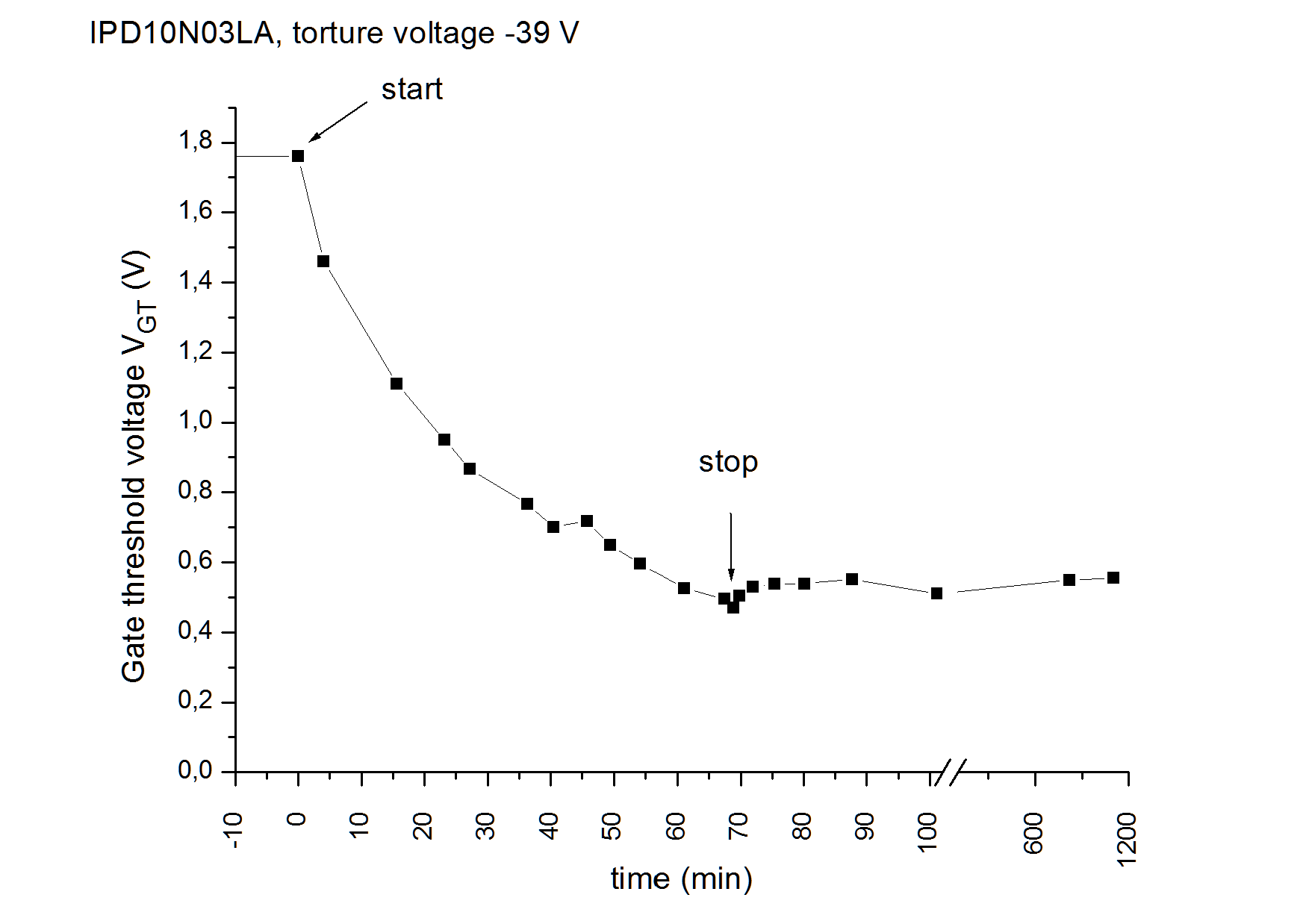
Gate threshold voltage measured right during the torture, by adjusting test voltage to the point where I could just see the led blinking. This is crude, hence the graph isn't very accurate. But good enough to see trends.
The total timespan of the plot is 20 hours.
I haven't converted the mosfet into depletion this time, as the process seems to have slowed down too much. I'll try cranking up the torture voltage a bit to see what happens.
-
First success!
10/16/2016 at 14:23 • 0 commentsSo I assembled the "blink torture" circuit, and continued trying to bias that poor MOSFET that I had heated to 400°C a few times.
At first, I was trying to combine high negative gate voltage and heat, but that appeared to only further damage the already half-killed mosfet.
Then I stopped heating it, and just cranked the voltage up and up. After passing through a few intermittent shorts somewhere around negative 30-35 V, I eventually arrived to -39 V. Cranking it higher caused more intermittent shorts, and while I was trying to penetrate them, I noticed that the LED started to blink brighter.
So, I set the voltage to -39 V, and waited. A few minutes later I was the happiest person on Earth, because I saw a gradual drop of gate threshold voltage. It was slow, but it was certainly happening!
After about half an hour, I got to the point where the mosfet was conducting a little bit at zero voltage on gate!
At that point, I stopped the process, and left it alone for a while, to test, how permanent is the biasing. The biasing did revert to some extent, so the transistor was again non-conducting at zero Vg, but the threshold voltage was still very low.
Then, I've set it up for further biasing. It was progressing slowly... and then the transistor decided to die. A high leakage from gate to source appeared, and I couldn't get it to vanish. Eventually I converted that leakage into a dead shorted completely killed MOSFET.
But the concept was proven! Now on to a fresh MOSFET!
-
The blink torture circuit
10/16/2016 at 14:06 • 0 comments![]()
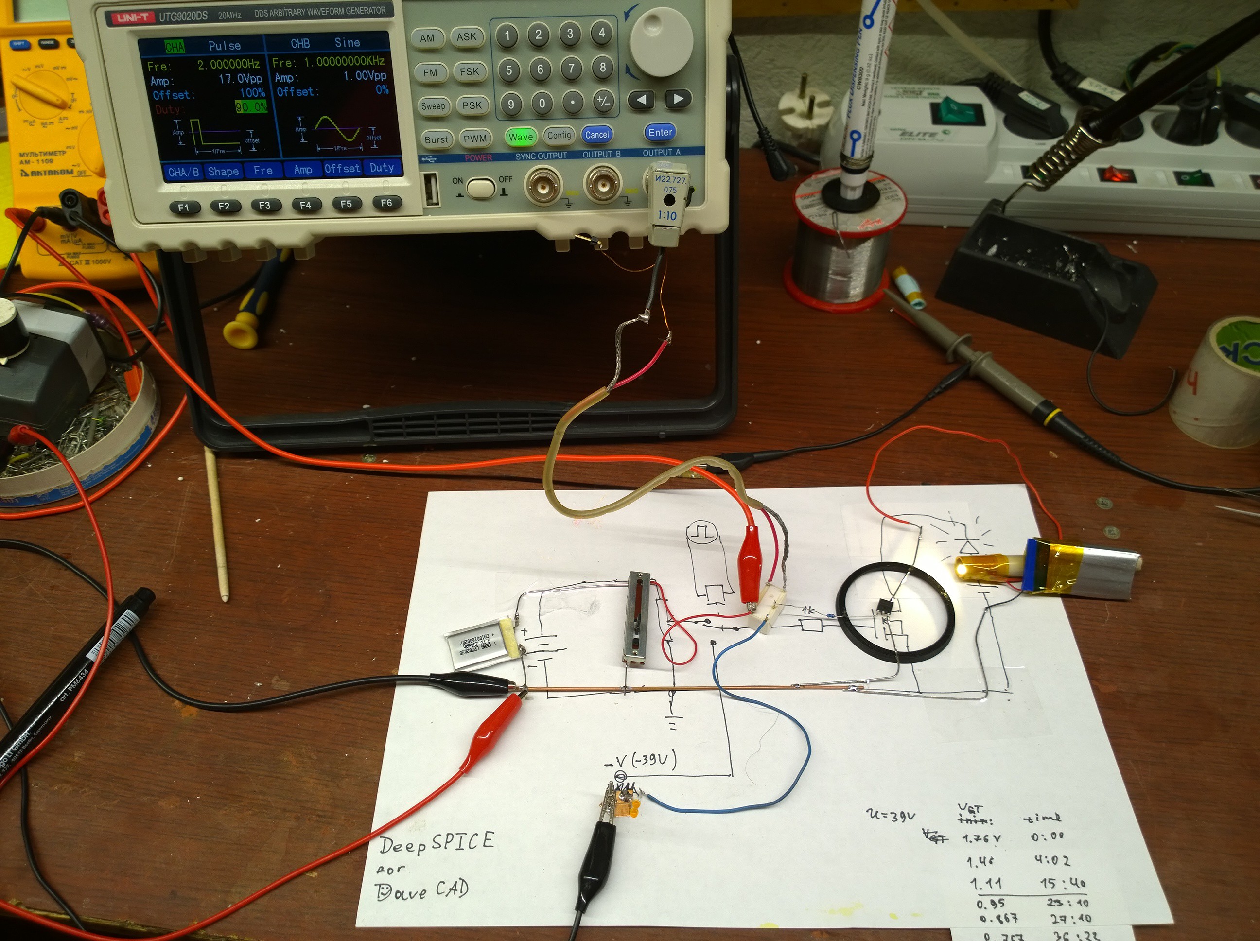
he circuit is quite simple. Source of gate voltage is switched between two options by a relay. The relay is driven by signal generator (you can use anything like Arduino for the purpose...).
One source is an adjustable low positive voltage. It is used to test gate threshold voltage of the mosfet under torture.
The other source is the large negative voltage, which is to cause biasing.
The mosfet's drain-source current is monitored by observing brightness of an LED. I am using a power LED and a Li-ion cell for this. Indicator LED will also do, but it doesn't allow to test for high currents.
The generator is set up so that 90% of the time, the large negative voltage is applied to gate, and periodically it is briefly switched to test voltage. To measure gate threshold voltage, I vary the test voltage (using that long linear pot) to the point I start seeing the LED blink.
The nice thing about this setup is that I can monitor how threshold voltage of the mosfet changes, in real time.
enhancement to depletion
DIY method to lower gate threshold voltage of regular MOSFETs, ultimately reversing it.
 DeepSOIC
 On the left, cross-section of the device is shown (n-channel MOSFET). Dashed line is a cross section for which band diagram is drawn.