Yannick (Gigawipf)
-
New TMC drivers!
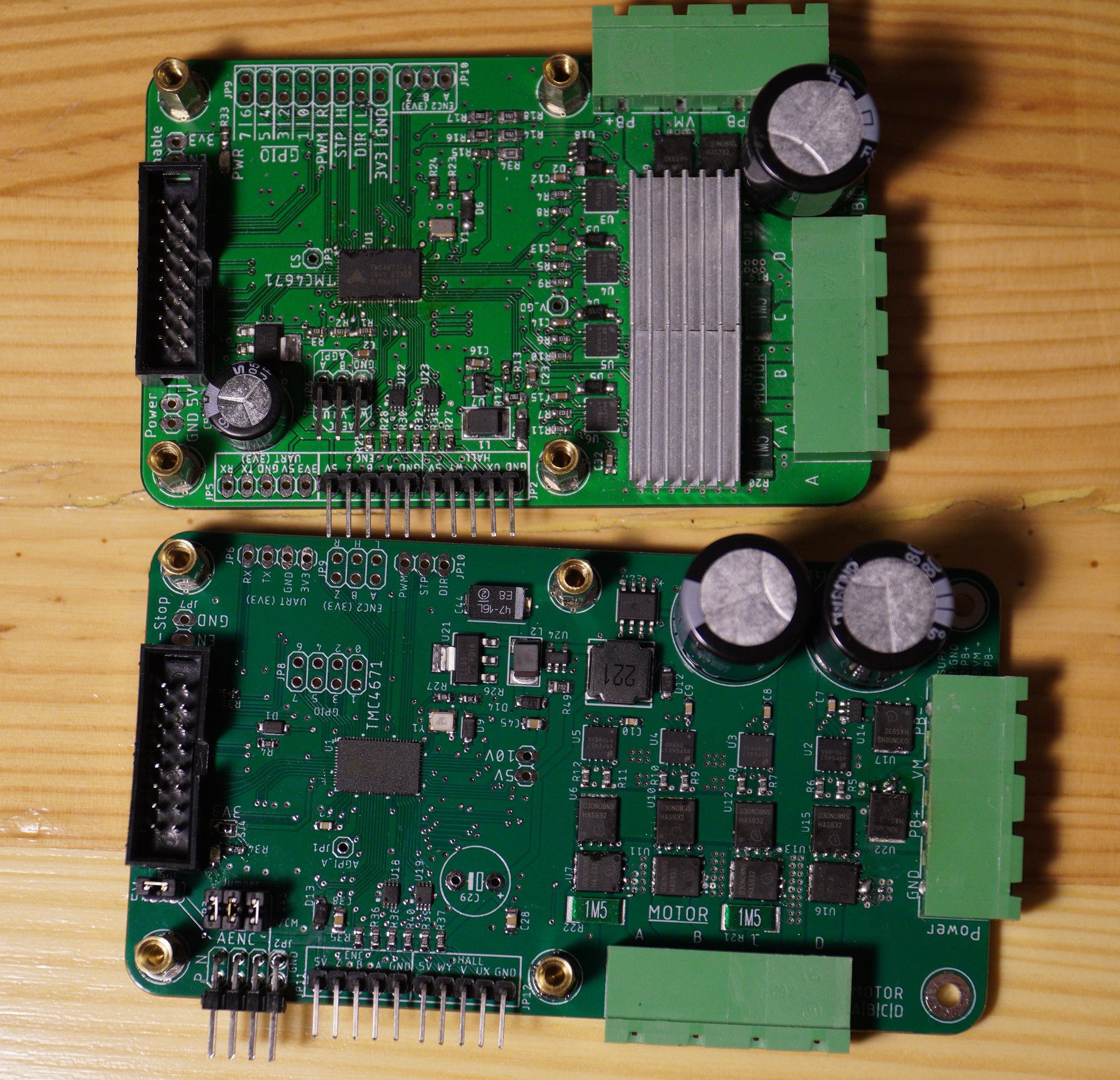
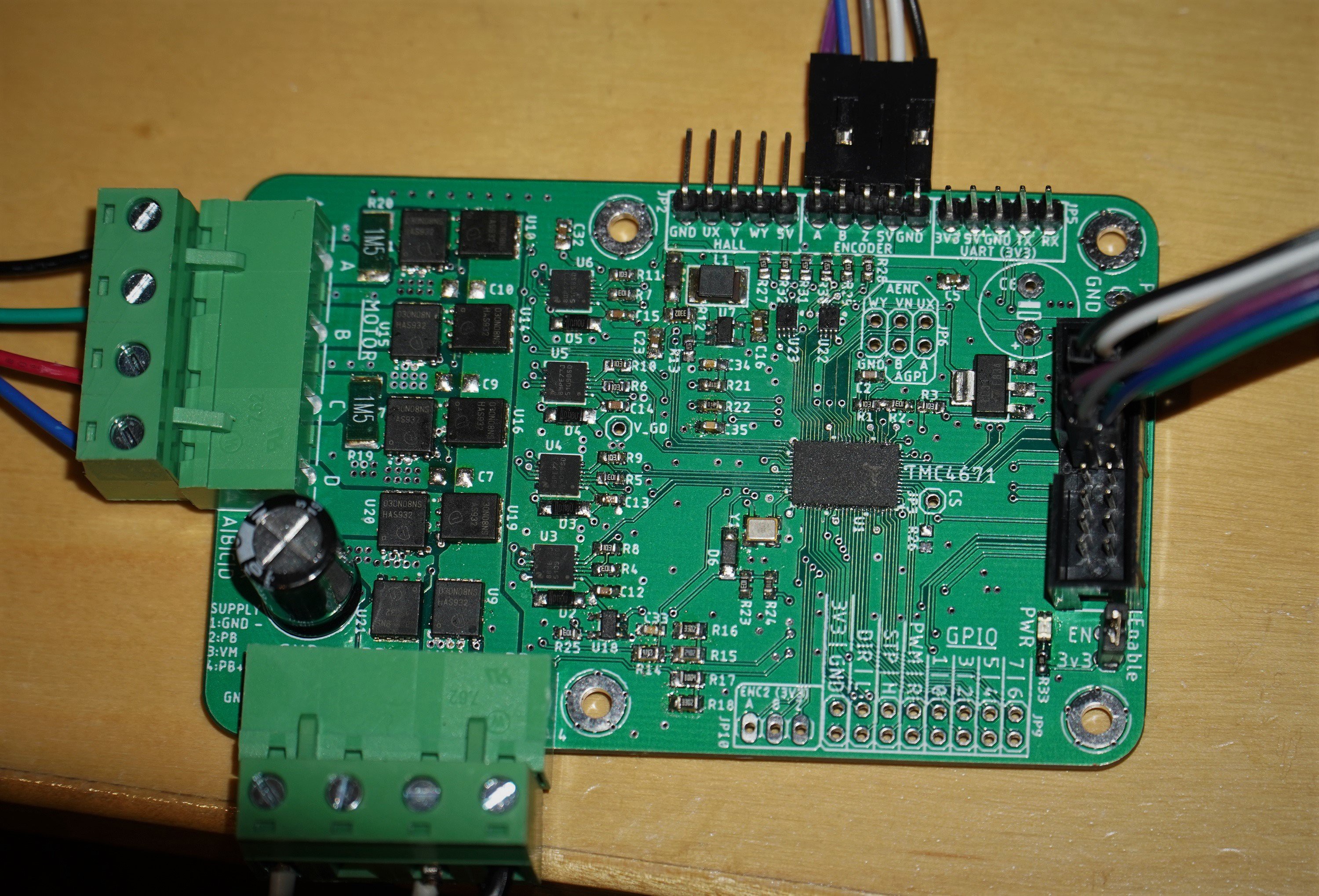
10/18/2020 at 20:16 • 1 commentFinally after a long wait the new TMC4671 boards are here!
This time almost fully assembled from the factory. Not going to make any more completely by hand...
The picture shows the old one compared to the new one.![]()
Changes include:- 2 motor caps
- Onboard 5V regulator
- Differential SinCos encoder inputs (Insane resolution)
- Common voltage reference for shunt amps
- Mosfets not blowing up on 48V (lowside gate pulldowns, safery zeners + 5v regulator for quick startup)
- LM74700 instead of LM5050 for much stronger and faster active diode switching.
- Better terminal layout for connecting motors due to rotated power stage.
- NTC temperature sensor
Update video hopefully coming soon with some details about the changes and sincos features. -
SinCos encoders and a tiny wheel
06/25/2020 at 19:25 • 2 commentsWhile working on the next pcb version one task was to improve the support for analog sine/cosine encoders.
With sincos encoders we have the option to use high resolution absolute encoders and in the next version hopefully even with differential inputs for less noise.
For testing i made a few AS5115 based magnetic encoders and mounted a magnet to the shaft of a drone motor as a test setup.
That gave me the idea to make a tiny ffb wheel :) -
Added 3 phase servo support
05/23/2020 at 20:54 • 0 commentsAs most high end direct drive wheels use servos instead of steppers servo support is important.
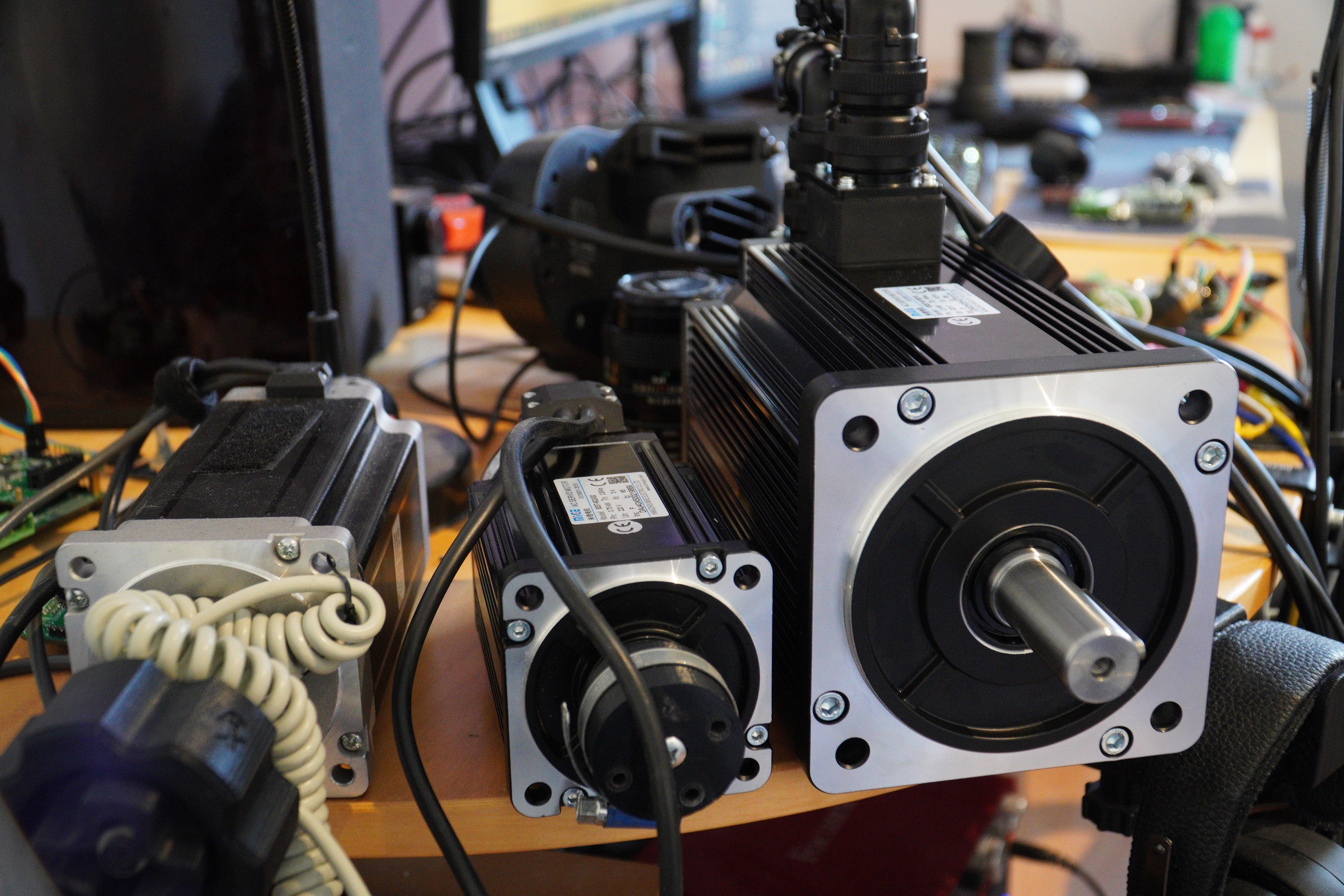
The 130ST-M10010 and 130ST-M15015 are the most common servos for this application with over 20Nm of torque.
In the last weeks i was able to compare the Nema34 stepper and a Mige 80ST-M02430 and a 130ST-M15015. Two very different servos.
The 80ST is with under 5Nm a bit weak but has very low resistance and good reaction speed while the 130ST has dangerous amounts of torque and a bit more mass and resistance.
For a wheel the 130ST is probably the best option here.
The next TMC motor driver will also have the new chip with a few fixes, an onboard step down for better reliability and will probably keep the external braking resistor as the large servo does generate quite a lot of voltage when being turned manually.Update summary from the last video:
![]()
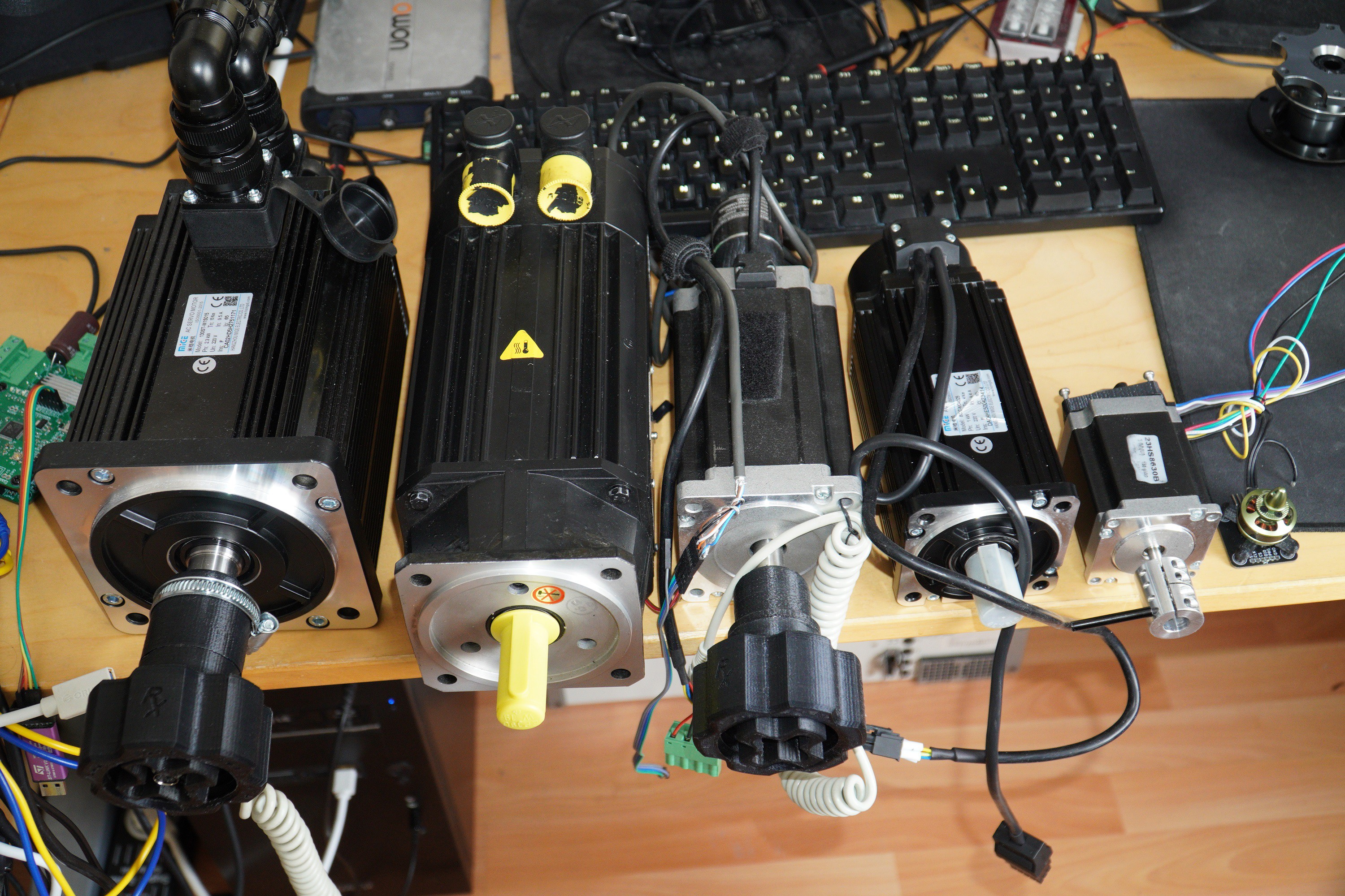
Reasonable motors are for example:
3 Phase servos:
130ST-M15015
130ST-M10010
80ST-M04025
80ST-M02430Nema34 Steppers with Encoder:
34HE59-6004D-E1000
34HS59-5004D +Encoder (E6B2CWZ6C or AMT132)![]()
Those are all usable motors :)
-
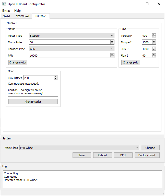
Developing a GUI
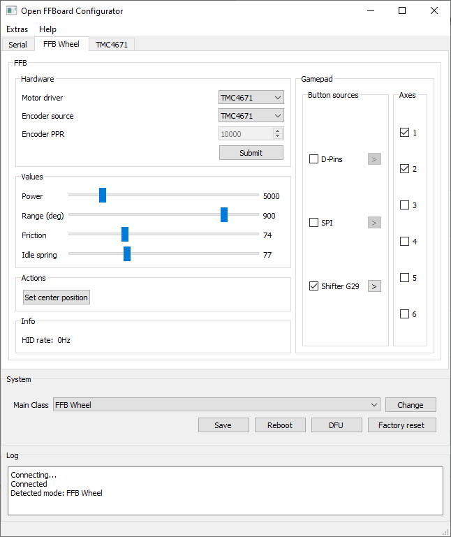
03/27/2020 at 11:15 • 1 commentThe setup procedure via command line can be confusing and error prone.
Therefore a graphical interface should help with the setup and tuning of parameters.I chose python with Qt as this allows rapid development of a nice interface for changing main classes or setting up the motor driver.
This is a very early version and later the most common setups might be done via a simplified wizard to reduce problems.
The DFU mode allows to flash new firmwares without a debugger. Remember to do a full erase if problems occur as sometimes the ST programming tool does not erase the correct sectors...
Later the DFU programmer will hopefully be integrated as well.![]()
![]()
The GUI can be found on Github (Ultrawipf/OpenFFBoard-configurator). -
Announcement video
03/13/2020 at 15:03 • 3 commentsAfter working on this project for a year now i feel its finally time to make an official announcement video detailing some of the ideas and the current state of this project.
Due to some requests in the end are also some longer racing demos of the OpenFFBoard in a wheel configuration.
In this video i am showing project cars 1 and assetto corsa.
Project cars 2 feels also great with that. Pretty much any racing sim should work nicely with this without drivers. -
Finally FFB again!
02/15/2020 at 13:56 • 4 commentsThe last days i spent preparing the firmware for a modular architecture, porting the old FFB code and improving it to a usable point.
Constants for the driver and some settings are stored in flash and loaded at boot so you only have to set parameters like motor type, main class, encoder parameters and button sources once.Thrustmaster wheels with buttons are supported now as well as 8 local digital pins as button sources.
Most of the effects are implemented and set to reasonable values.
Its HID Physical Interface compatible so it works without drivers for any supported platform and game.Here is a short race with the new boards on low/medium power for checking some parameters:
No comments on my driving or the mess of a table please^^
The motor used is a Nema34 with a 10k ppr encoder on the back with a supply of 19V (Notebook psu).
The large cap on the left is connected to the internal motor power rails to buffer the power without enabling the braking resistor too often. You don't need a cap this large but having more capacity is always a good idea here.
I am now waiting for a new version of pcbs to arrive with better hall/encoder filtering as with some very noisy motors the pwm can cause some issues. Apart from that i am pleased with how good it works and feels and with some tuning it should get even better.
-
Improving noise with filters and better amps
02/04/2020 at 17:23 • 2 commentsIn the first version of the TMC board i tried INA282 current shunt amplifiers.
It turns out despite having very good specs on paper they are extremely susceptible to fast rising common mode voltages.
And we have these a lot as the TMC needs to measure currents on the floating motor outputs.
This meant extremely bad noise on the current measurements.
As an alternative there are the AD8417 which are much better suited for this application for the same price.See for yourself what a difference this makes:

Open loop current of slow 3 phase motor Looks pretty good considering that this is on a low scale and we can go MUCH higher and maybe even improve the noise with filter tuning.

INA282 at more than double the current Looks very bad right?
This is because the INAs output spikes >1V up or down for up to 15µs after almost every pwm cycle (25-50khz).This is the output of the INA282 with no motor current. Only pwm active. yup. pretty bad.
![]()
Obviously we are now using the AD8467. For even better noise the AD8468 with low gain could be used but this would decrease the maximum current even more. I am aiming for >25A fullrange for this version for now.
By using different shunts or the lower gain AD8468 we can decrease or increase the limit depending on the application.
We will also add low pass filters to the encoder and hall inputs as with some motors significant pwm noise gets back through these lines and causes glitches. This means even more components to solder :/
Next step is to order new pcbs to fix the previous errors and write the firmware.
The firmware is currently in a stage where most base features are working and i am implementing an example for FFB soon
Also as the board is quite small there is not much room to add capacitors causing high ripple on the motor voltage rail when backdriven as there is currently only space for one larger cap.
When used with large motors it is recommended to add external caps between GND and PB+. -
Boards. More Boards. Finally TMC4671!
01/29/2020 at 22:25 • 0 commentsAfter a long time planning the pcb and waiting for parts the first motor driver board is finally assembled.
This is a fully featured motor driver with dedicated power stage for high currents, support for a braking resistor and active backfeed protection for high efficiency.Braking resistor can be activated either automatically via the TMC at a hard voltage level or forced externally at lower levels as well (if internal voltage higher than external for example)
Encoder and Hall effect inputs are buffered and protect the TMC. All pins of the TMC are broken out to accessible headers.
This board is not just for the FFBoard. It can be used for other projects as well.
![]()
Its made to connect to the STM board via a ribbon cable or stack directly under the STM board for a compact setup.
USB Interfaces Yes! First open loop rotations! (Connected to a Trinamic Landungsbrücke via SPI)

TMC4671 powered first rotation Of course there are still issues as this is the first hardware prototype of this version and changes might be made:
- INA232 shunt amplifiers are extremely common mode step sensitive despite very high claimed CMMR. The slopes are too steep while switching. This causes high noise in the measurements.
- Change amps to AD8417 which might behave better but with higher gain maximum current is slightly lower
- Smooth spikes out with more aggressive low pass filtering
- AD8478 and higher value shunts for even better noise but lower efficiency
- Embarrasing error: The Oscillator is permanently disabled due to gnd at tristate pin... Fix: Scraped pad off... Easy fix in next pcb revision.
- Despite analog inputs on the tmc being 0-5V the single ended VM input only measures half range and a maximum of 1.25V. Very strange decision from tmc...
- I did not catch this before so we will need a new pcb for this. Not a big deal for now because its only relevant for the forced brake resistor failsafe enable by the tmc which should not even be needed as the STM will do this normally
Apart from these issues that can be easily fixed in the next revision the important parts seem to work correctly and the board can be used to start developing the software interface and initialisation routines.
Also those industrial terminals are pretty expensive and might be changed to open screw terminal style which are also better for some permanent installations.
- INA232 shunt amplifiers are extremely common mode step sensitive despite very high claimed CMMR. The slopes are too steep while switching. This causes high noise in the measurements.
-
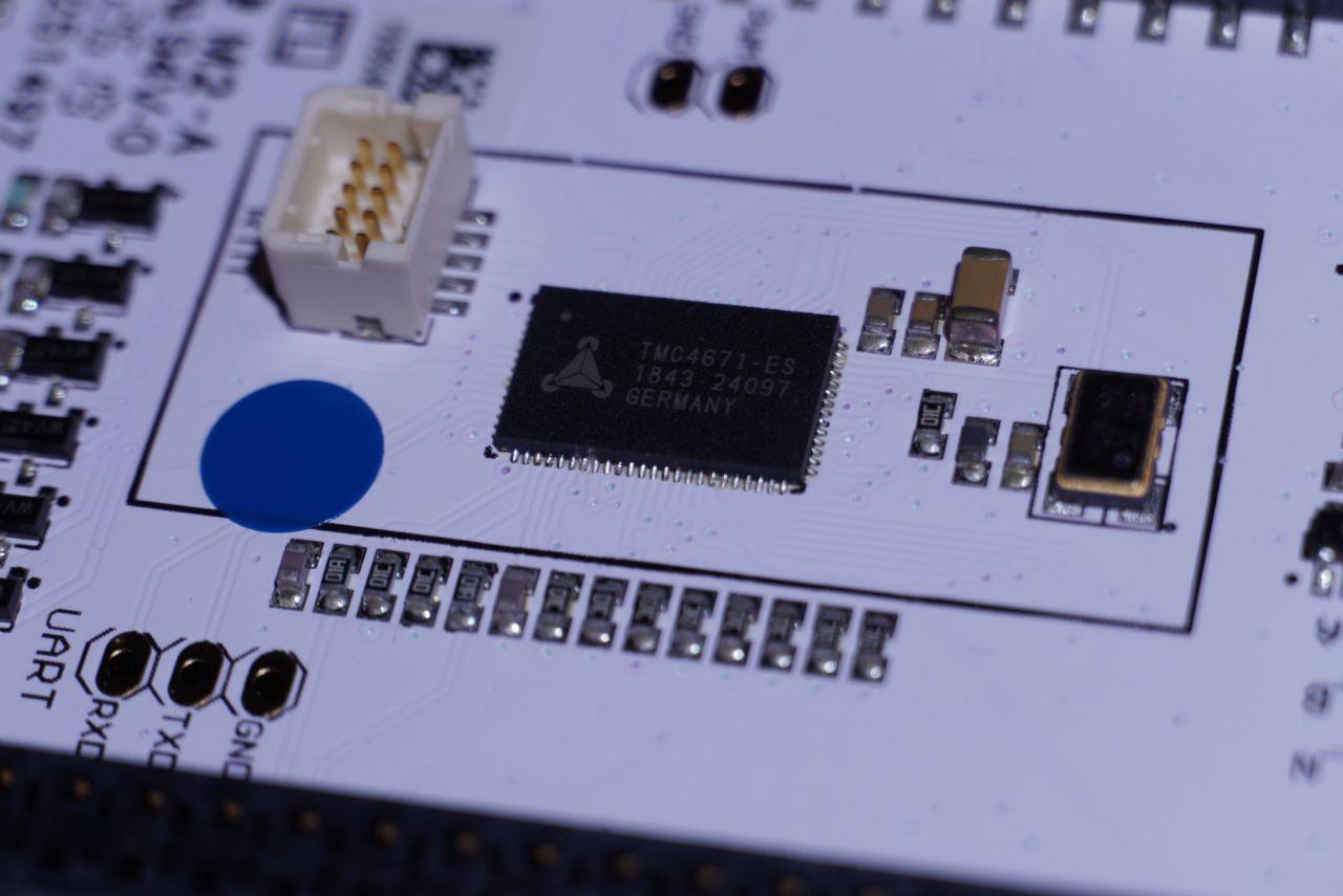
Testing the TMC4671
11/23/2019 at 11:56 • 2 commentsAs mentioned before the reference motor driver could be powered by a Trinamic TMC4671.
This motor controller promises everything a universal torque mode motor driver should do while being compatible with 2 phase steppers, 3 phase servos and DC motors with the same power stage. Nice.
Big thanks to Trinamic MC for sending me a TMC4671 Devkit. This way i can begin testing the features before the fixed chip is sold again and the final pcb is manufactured.![]()
I tested the chip with the TMC IDE Trinamic provides for this kit. This software nicely explains with wizards in the form of a tutorial how to setup the core parameters of the TMC4671.
It also helps debugging with graphs and register browsers.
I have made a setup with a 2 phase stepper, an 8192ppr encoder and torque mode to see how it responds and it pretty much does everything the old OHSC with the powerstep01 did but much better and in hardware. Nice.
A modular design would also allow support for multiple TMC Motor Drivers on one SPI bus for 2 or 3 axis systems.And if you perfectly align the encoder speeds impossible for normals stepper drivers can be achieved.
The next step is to finish a pcb and wait until the TMC4671 is sold again. This might be the best solution fo a reference motor driver for this project.
*Update*
Trinamic said to me that the TMC4671 in the fixed version is planned to be released in march 2020.
Until then the current version is sold that has a few hardware problems.
This means that the next prototype will still have the old version of the chip.
For SPI control and FFB the bugs should not be an issue apart from having to slow down the spi clock a bit for now to avoid a data corruption issue.
The step/dir interface does not work and the adc and spi MSB might have sporadic glitches which fortunately did not affect the motor control in the tests.
All known issues are listed in the errata of the datasheet. -
Change of project direction. More FFB, more compatibility
11/04/2019 at 11:29 • 0 commentsThe goal of this project was originally to create an open source motor driver focussed on racing simulation controls.
There are many different motor drivers but not many of them were really suited for the task AND hobby budget friendly.
It makes sense to focus this project on a simple open source force feedback interface as this is the part where the community lacks a good and open solution.
Therefore the main goal will be to develop a universal FFB controller (Open FFBoard).
While the first prototype (OHSC) did kind of accomplish this goal it was clear that for reliable use and high accuracy the powerstep01 was not suited. They sometimes locked up or died as they were not used as intended and only provided 7 bits of resolution. I realized there is no way to reach the goal of reliable and high fidelity torque control with this device and there is a reason servo drivers are expensive.
I was pointed to the Trinamic TMC4671 motion controller which would do everything needed directly in hardware and can be configured for steppers, 3 phase servos and DC motors simply via spi with the same hardware. The TMC4671 had as few issues in the first revision but will be fixed soon Trinamic promised me. Therefore i am confident that it should make things more robust and simpler on the software side if the task of controlling the motors is completely done by a separate chip.Building an external 4 half bridge power stage is more complex and expensive but will allow for much better cooling and higher currents.
The goal remains to create a budget friendly kit but it is clear that the motor driver will get more expensive. (Think ~30$ parts OHSC -> ~50$ BOM cost TMC board + more work. We need 10 mosfets and drivers... etc.). From my calculations it should still be possible to make a kit like this below 100$ :)The current idea for the project will split into two main parts:
1.
An open source Force Feedback interface board with an STM32F411 for usb communication and control.
This will support different motor drivers and will be modular. You can use your own motor driver or control schemes by writing c++ classes for this controller. The main software parts will be the motor control part for encoder input or force output and the control interface which will be USB HID for most users but could also be changed into a class that outputs PPM values depending on the steering wheel position and receives force values back to pass to the motor interface.
For example a VESC or a commercial servo driver could be made compatible.2.
A reference motor driver based on the TMC4671. This will be the intended motor driver for a direct drive wheel but can also be used as a standalone motor driver or development board for arduinos and different purposes. The STM board will be optimized for this motor driver.The next step is to test if the TMC4671 fits this goal and which motor drivers are a good alternative.
This will be interesting and i will keep you updated. The new boards are almost finished and i am waiting for Trinamic to release the chip soon.
Open FFBoard
A modular and open source force feedback interface and motor driver for DIY wheels and controllers