 Bud Bennett
-
The Second Pass Prototype
04/20/2019 at 19:09 • 0 commentsA list of new features and/or changes after testing the first prototype:
- Only three VL53L0X distance sensors. Five sensors is confusing and not necessary. There will be dead zones because the outer two sensors will be 50° off of the front sensor. This was not a problem in the first prototype when two of the sensors were disabled.
- Exchanged the Arduino Feather for the Arduino ItsyBitsy -- its a lot smaller with nearly all of the same capabilities.
- Added a LIS3DH accelerometer for motion and tilt sensing. This will allow the system to mute when no motion is detected or the unit is tilted significantly off-axis (i.e. sleeping). It should also disable the forward sensor detection when Lucy is pointing her head at the ground.
- Added a battery charging function. 500mA when the USB is plugged into a 5V source. The charge indicator is a LED on the Itsy via the D12 pin.
- Added a separate PIC10F322 µC to monitor the battery voltage and put the system to sleep (<100µA) when the battery voltage drops below about 3.3V. The PIC will also monitor the accelerometer activity and put the system to sleep after TBD seconds of inactivity -- a battery saving measure.
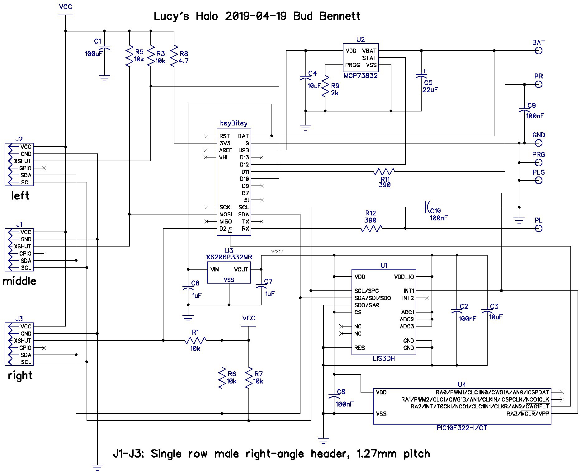
The Second Pass Schematic:
![]()
The MCP73832 is the same as the MCP73831 but the STAT output is a pulldown only. The ItsyBitsy will present a weak pullup on its D12 input and only pull to 3.3V.
There is a separate 3.3V LDO regulator providing power to the accelerometer and the PIC. The accelerometer is configured to latch the INT1 pin high when motion is detected above a certain threshold. The latch is reset when the Itsy reads the INT1_SRC register every TBD seconds. If INT1 doesn't go high after TBD seconds then the PIC will disable the Itsy by pulling down the En pin, which turns off the Itsy's 3.3V regulator. This puts the system to sleep with a relatively low current drain. If the accelerometer detects motion again it will assert INT1 and the PIC will re-enable the Itsy.
(Note: the connection from INT1 to D7 is not necessary since the Itsy can read the status of the accelerometer over the I2C interface, but I thought there might be some value to have be able to read the INT1 pin for debugging purposes. This brings up a sticky issue because the accelerometer and the Itsy are on two separate supplies. The Itsy's LDO is fed by two Schottky diodes to pick up power from either USB or BAT. When the battery voltage gets below about 3.5V the Itsy's supply voltage will fall below 3.3V because of the drop across the Schottky. But I measured the total voltage drop between BAT and the 3.3V supply as only 200mV, which should not cause a latchup problem.)
The PIC has one other function besides monitoring INT1. It also measures its supply voltage and will shutdown the Itsy if the implied battery voltage drops below TBD. This PIC has an on-board 8-bit ADC using VDD2 as a reference. The ADC input will be an internal FVR(Fixed Voltage Reference) set to 2.048V. If the measured ADC value rises above TBD, then the Itsy will be put into a sleep mode by pulling the En pin low. This should save the battery from imminent damage.
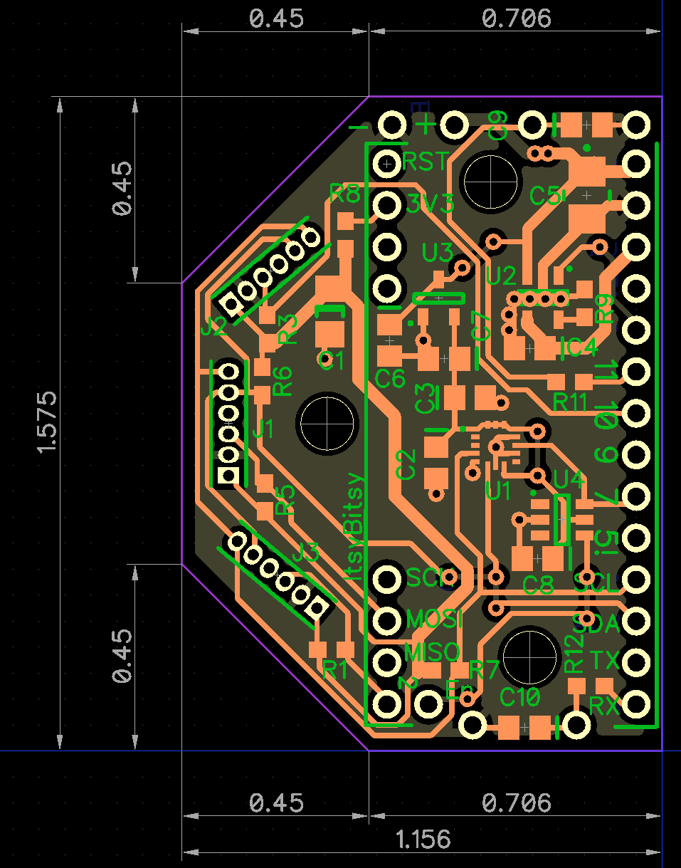
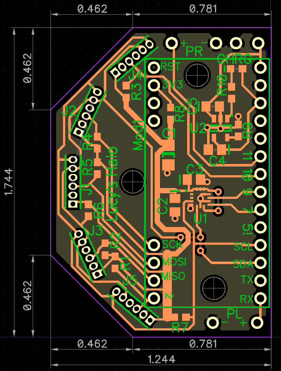
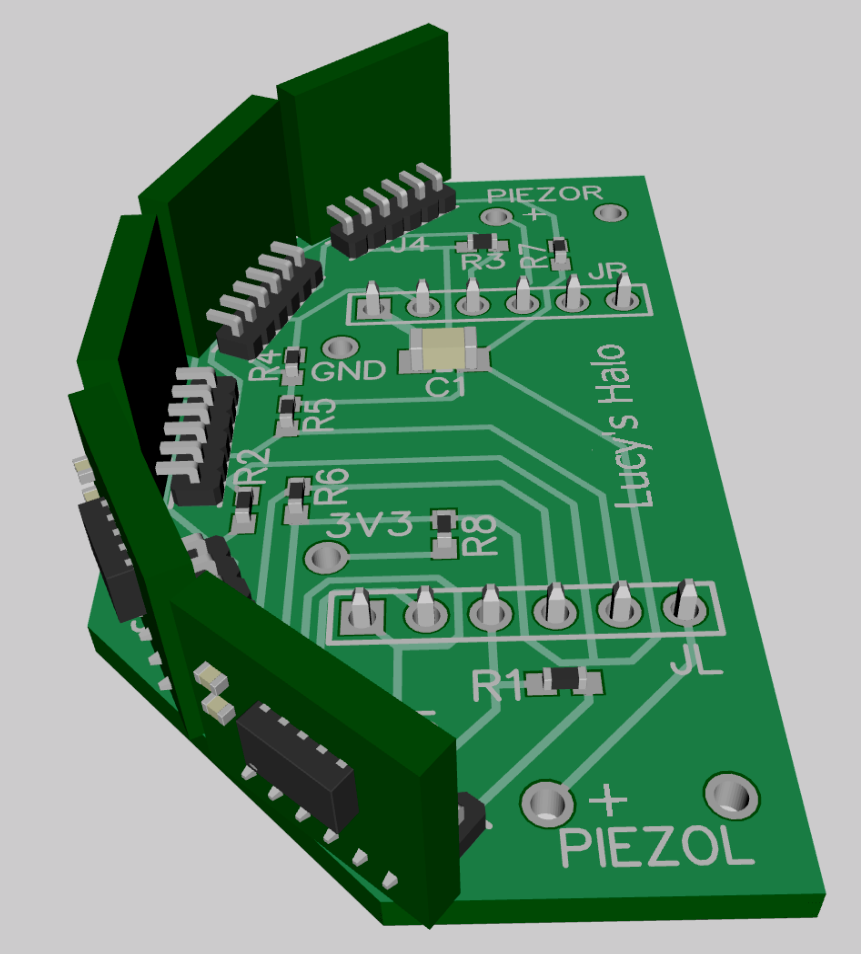
The Layout:
![]()
It's smaller by quite a bit -- only 1.575" x 1.156" (40mm x 29.5mm). The PIC10F322 is a SOT26 and two pins are unused! The battery and USB connection are at the top -- I'm a bit worried that the right speaker might interfere with the USB connector access. Hopefully that will be solved by clever packaging.
![]()
I'm waiting to see the results of a couple more training sessions before I order new PCBs.
-
Dog Trials (more like...travails)
04/16/2019 at 17:34 • 2 commentsThe days are not sequential. There were days between where nothing happened.
Day 1:
I started out by just securing the prototype to Lucy’s head with a long rubber band. She immediately shook it off and it went flying across the room.
The next approach was to run two short steel wires from her collar to the back of the unit. She shook it again and it would flop down sideways or backward. It would not remain on her head.
Another version used a stiff nylon strap from her collar that ran under the prototype. Same problem as above.
Clearly, I needed some help from from somebody with knowledge and skill in the physical world...my Wife (who can sew).
Day2:
Whenever you have more than on person on a project progress slows to a crawl. The Wife’s priorities aren’t the same as mine and she has veto power over the activities upon which I depend. We both agreed that some sort of bonnet would be best. The first attempt was more like a hood than a bonnet. I had no input as to the color. It had two holes for Lucy’s ears, but quite a bit of material on the top, bottom and sides. Lucy had major issues with it when we put it on her without the electronics attached: she shook her head repeatedly, scratched it from the sides with the front paws and then sat down and used her rear paws to really do a job on it. The bonnet stayed put, but looked uncomfortable to me. I thought her issue with that particular bonnet was that it rubbed against her ears and that was annoying.
![]()
Day3-Day5:
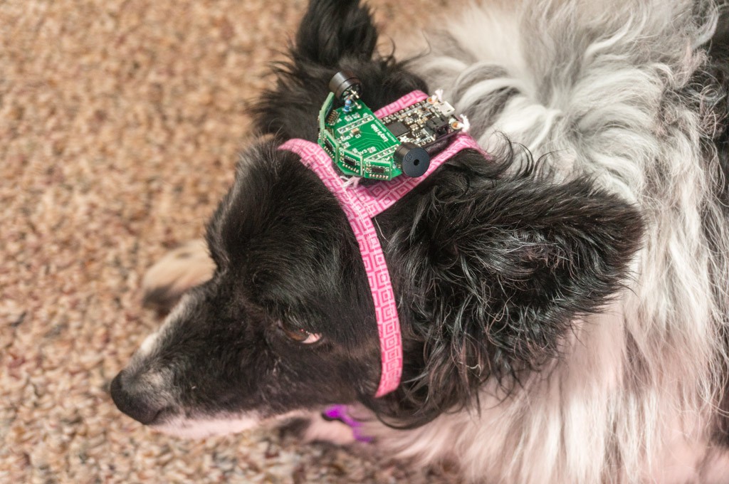
I suggested to my Wife that a better approach might be an upside-down jock strap (but not in those terms.) Basically, two ribbons with a connecting piece of cloth to run between Lucy's ears where the electronics could attach. This was produced with a bit of grumbling. The ribbons connected under Lucy’s chin with pieces of mating Velcro. Again, I had no input for the color - Pink! I glued a softer piece of foam pad below the electronics to increase the comfort level.
![]()
Lucy got used to this headdress pretty quickly, first without the attached electronics and later with, but still executed the obligatory shake rattle and roll. All of the abuse took its toll on the electronics. One of the speakers went flying across the room — the speakers have a great big gob of hot-melt glue as reinforcement now. I’m surprised that’s the only thing that broke so far.
The first time that Lucy wore the complete package with battery and operating electronics was in a bright room. Every time she would shake her head the position of the sensors on her head would change — either sliding slightly backward or moving one half inch to one side. Many times the hair on her ears, or the ear itself, would block the outer sensor and the unit would be inhibited (objects less than 50mm inhibit the system.)
There was a five minute interval where everything worked and she followed me around the house. It was bright so she could see fairly well, but when she drifted too close to an object or wall the unit would flash a detection event and I could tell that she noticed the beep from the speaker.
Later on in the evening when it became darker I put the powered prototype on her again. The same issues with alignment and head shaking persisted, but there was a short period when it seemed to be working correctly. I tried to inform her as to the function of the unit by bringing my hand toward her to activate the speaker and then touching her head from that side. Since it was dark, Lucy was moving much more slowly and appeared to respond to the audible feedback when she got too close to an object or wall. Unfortunately, this prototype doesn’t mute when it’s not moving or tilted so I had to prevent her from lying down or sitting close to an object that caused the unit to keep beeping for no good reason. The entire session came to an end when she shook her head and disconnected the solder joint from the negative terminal of the battery.
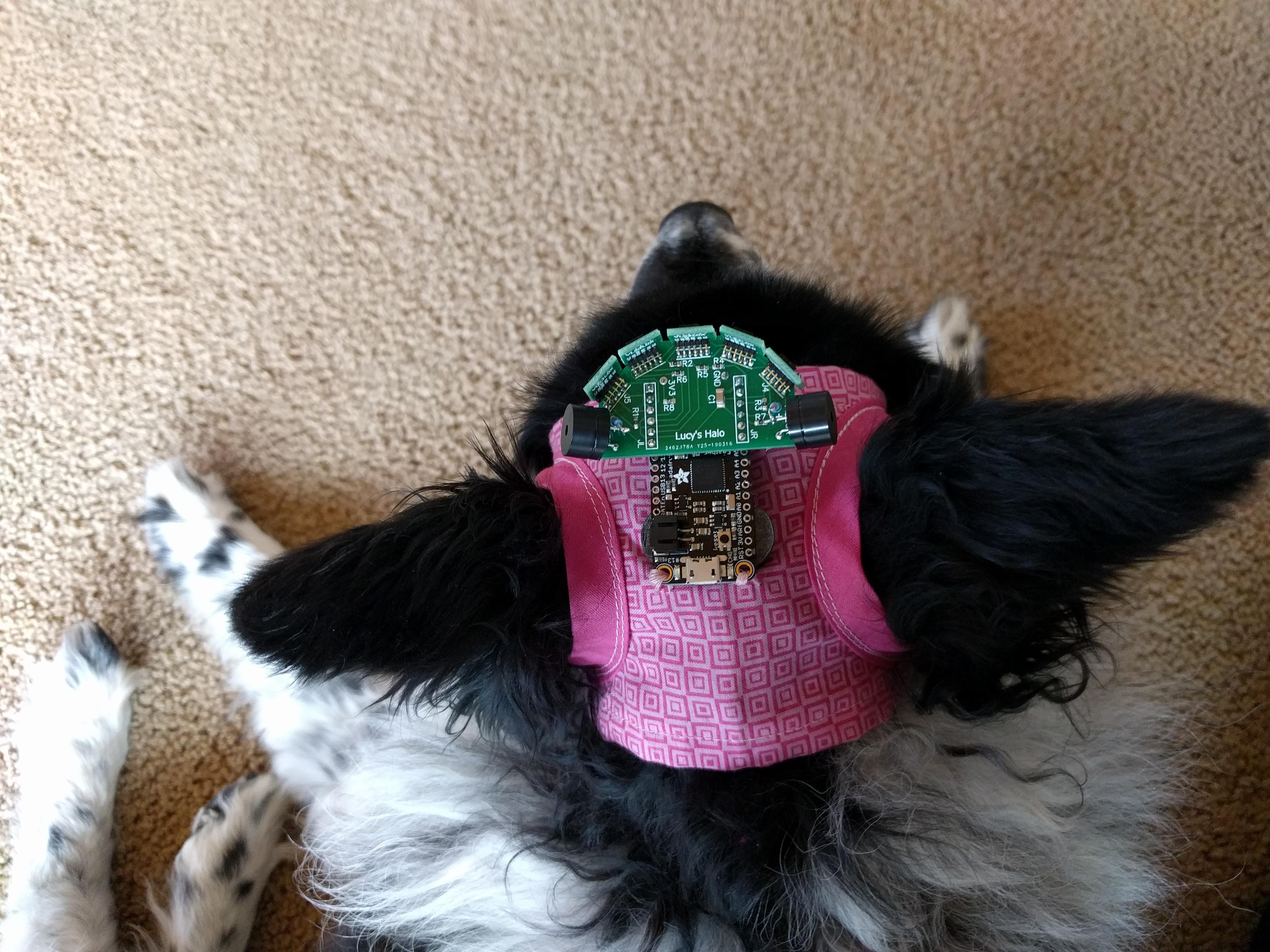
Day 6:
Back to the old bonnet style. The jock strap version did not keep the prototype in the correct position after Lucy's head shake. The larger bonnet is better suited for the larger electronics package we're using now. I still need to readjust it a bit after she shakes it, but in general is is a better temporary solution.
At night I rearranged the soft furniture in the living room and turned down the lights. Lucy was fitted with the bonnet and electronics -- the 14500 Li-Ion battery hung by rubber bands from her collar. She was an unwilling participant. I called her from around the room and observed her progress negotiating the maze. The unit pretty much performed as expected, but it was difficult to determine if Lucy was understanding what it was doing. She seemed to pay attention to the feedback from the sides that warned her of a nearby object, but she occasionally bumped into something head on.
I think the problem may be that the unit would beep at the ground whenever she lowered her head so she was ignoring that data after a while. The unit had detection thresholds of 500mm/front and 400mm/sides.
Day 7 - The Dog Whisperer:
We invited a local dog trainer (dog psychologist?) to observe Lucy with the prototype and give us some tips on how to train her to understand and use it. We decided to temporarily disable the front sensor since it was detecting the ground when Lucy pointed her head in that direction, which was often. We thought that this would confuse her initially, so for training purposes its gone.
The trainer suggested that when I train her to the prototype I have a short leash connected to her harness and lead her around the training space populated with cones or empty cardboard boxes. When she bumps into a box I should gently pull her back with the leash and give her some verbal feedback. Training sessions should be no more than 5 minutes in duration.
Going Forward:
This prototype was made to prove out the concept and identify changes or improvements in both the hardware and software. It has done its job in that regard. I'll be moving on to the second pass prototype after a couple more sessions with Lucy.
-
Human Trials Begin
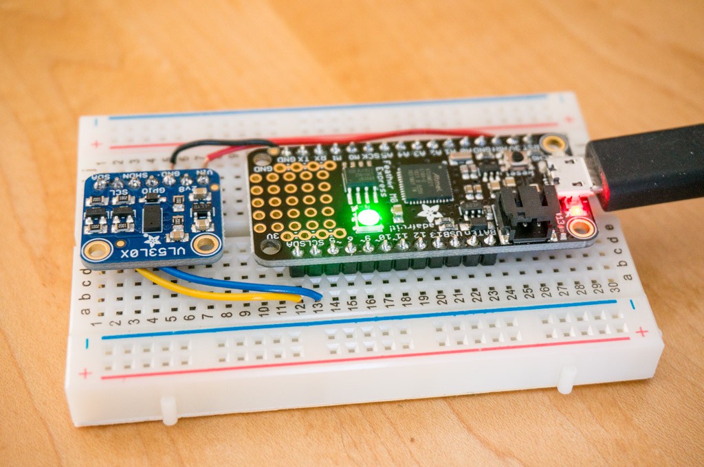
04/02/2019 at 00:07 • 0 commentsThe PCBs and parts have arrived. The near-term objective is to create a working prototype halo that will prove the concept using the Arduino Feather M0 Express along with a simple motherboard for the sensors.
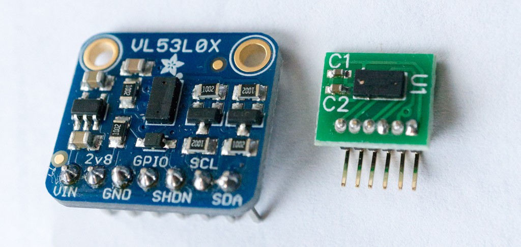
I removed the VL53L0X sensor ICs from the AliExpress boards and installed them on five daughterboards. This was more difficult than expected. The VL53L0X sensors seem to be sensitive to heat. I melted the first sensor that I removed from the AliExpress board while attempting to solder it to the daughterboard. The most satisfactory method was to heat the AliExpress board from the bottom, with a hot-air gun, until the sensor came loose. Then I turned the sensor over and added solder bumps to the pads with a soldering iron set to 300°C. I spread flux over the pads on the PCB and created solder bumps on those pads as well. I placed the sensor over the PCB pads and heated the PCB from below until the solder bumps melted and the sensor moved to align with the PCB pads. This method prevented the sensor from being damaged by the hot-air gun. The final result looks pretty good (compared to the huge Adafruit sensor board).
![]()
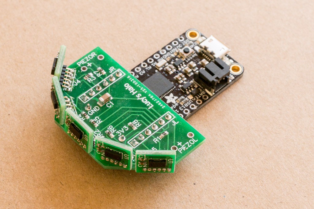
I soldered the five daughterboards onto the prototype motherboard and the code worked! All five sensors were configured and report distances. (I was absolutely amazed that all five sensors were functional.)
![]()
The next step is to attach the piezo speakers, and begin to evaluate the performance using humans (i.e me) as guinea pigs.
Early Human Trial Feedback:
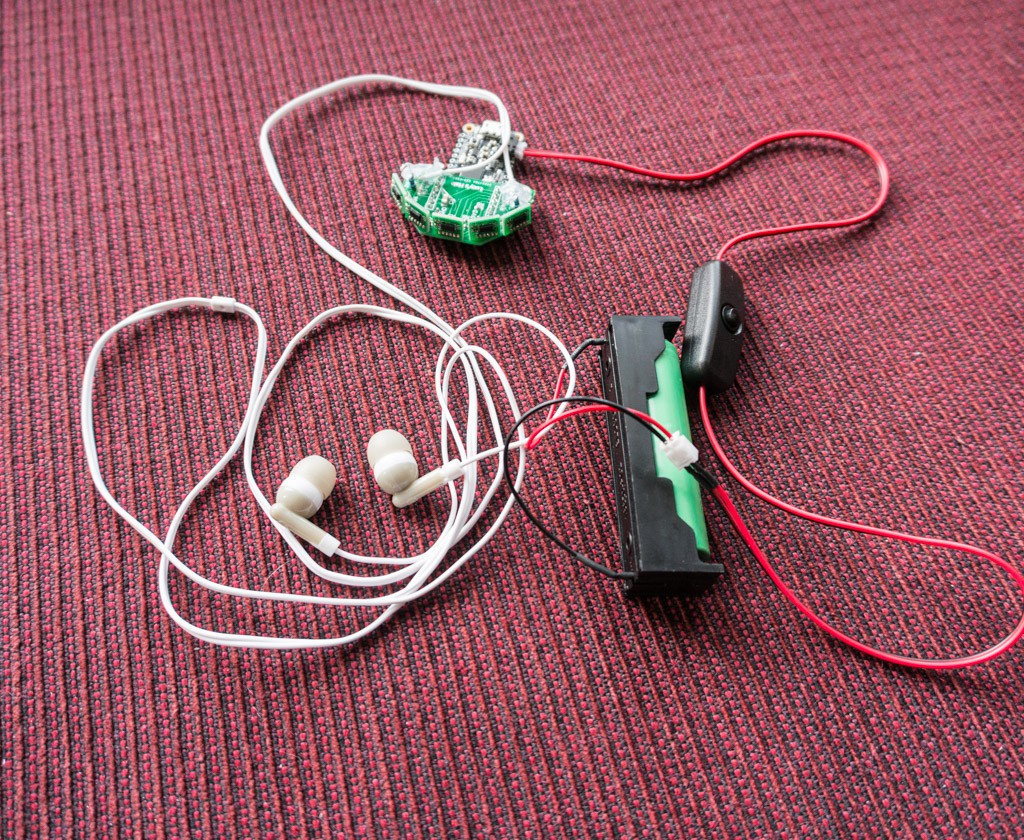
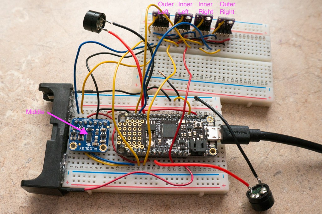
[2019-04-05]Humans are different than dogs. I hooked up an 18650 Li-Ion battery and switch to power the prototype. I also added a pair of $1.00 earphones to be able to hear the audio feedback. The earphone wires are solid core ultra thin, so I had to glob hot-melt glue over the solder joints to provide a minimum amount of strain relief.![]() The code needed some extra features to make it useable: the PWM output were generating spurious frequencies when set below about 800Hz — this was confusing, I increased the PWM frequency and added a low pass filter to slow the rate of change of the PWM frequency (noise in the distance measurement) that was causing a warbling of the tone. There were a few minor code changes to simplify and make it easier to make global changes like maximum detection distance and other parameters. It seems to be performing acceptably now.When I first tried to use the prototype it was immediately apparent that two sensors either side of the middle/front sensors weren’t making any discernible improvement. The audio mix did not indicate that the nearest object was slightly left or right of the mid point. I changed the code to just use three sensors (middle and two outer) with better results. When you are dependent upon these sensors you tend to sweep the area ahead slightly back-and-forth so having complete coverage is not a big advantage. When I stopped scanning those sensors the update rate improved and made a big difference in the speed of the feedback.I quickly found out that the vertical field of view of the sensor was too small to be very effective for tall humans. I kept bumping into things because: a) the response time was too slow with five sensors, b) the maximum sensor distance was set to 500mm which is too short for humans, and c) the sensor was too high off the ground. Things improved with only 3 sensors set to a max distance of 700mm. I’m considering modifying the code to increase the max distance sensitivity of the middle sensor and have the outer sensors have shorter detection distances. This would help when trying to navigate the opening to a room when the two side sensors are both reporting obstructions.
The code needed some extra features to make it useable: the PWM output were generating spurious frequencies when set below about 800Hz — this was confusing, I increased the PWM frequency and added a low pass filter to slow the rate of change of the PWM frequency (noise in the distance measurement) that was causing a warbling of the tone. There were a few minor code changes to simplify and make it easier to make global changes like maximum detection distance and other parameters. It seems to be performing acceptably now.When I first tried to use the prototype it was immediately apparent that two sensors either side of the middle/front sensors weren’t making any discernible improvement. The audio mix did not indicate that the nearest object was slightly left or right of the mid point. I changed the code to just use three sensors (middle and two outer) with better results. When you are dependent upon these sensors you tend to sweep the area ahead slightly back-and-forth so having complete coverage is not a big advantage. When I stopped scanning those sensors the update rate improved and made a big difference in the speed of the feedback.I quickly found out that the vertical field of view of the sensor was too small to be very effective for tall humans. I kept bumping into things because: a) the response time was too slow with five sensors, b) the maximum sensor distance was set to 500mm which is too short for humans, and c) the sensor was too high off the ground. Things improved with only 3 sensors set to a max distance of 700mm. I’m considering modifying the code to increase the max distance sensitivity of the middle sensor and have the outer sensors have shorter detection distances. This would help when trying to navigate the opening to a room when the two side sensors are both reporting obstructions. -
Five
03/20/2019 at 20:20 • 0 commentsThe AliExpress sensors arrived yesterday. They were not what I thought I ordered. Chalk it up to operator error. In any case I was able to assemble the sensors and plug them into another protoboard. It's not pretty, but it works.
![]()
The Feather was able to assign new addresses and then extract distance data individually. The sensors came with a bit of Kapton tape affixed to the top. This caused some problems with crosstalk that manifested as a false detection. Once the Kapton was removed the artifacts disappeared.
There were a few problems with the code. I learned that the last sensor in the list should be assigned the 0x29 address. Otherwise the sensor will respond when the next sensor in the list is powered up.
My iMac desktop machine had a lot of problems mounting the CircuitPython drive when all of the sensors were attached. i moved the development boards to my Raspberry Pi desktop (making my wife temporarily happier, since I was hogging the iMac). So far so good with the RPi. Time will tell.
Another interesting feature of the VL53L0X sensor is that the reported distance is *much* greater when the object is near the outer edges of the sensor's detection window. You can see this from a test that I performed by moving a white card from the left to right, keeping the distance to the sensors relatively constant.
distance 0 = 215
distance 0 = 178
distance 2 = 420
distance 0 = 168
distance 2 = 286
distance 0 = 158
distance 2 = 232
distance 0 = 155
distance 2 = 227
distance 0 = 149
distance 2 = 205
distance 0 = 149
distance 2 = 192
distance 3 = 460
distance 0 = 150
distance 2 = 186
distance 3 = 348
distance 0 = 141
distance 2 = 183
distance 3 = 295
distance 0 = 146
distance 2 = 170
distance 3 = 255
distance 0 = 140
distance 2 = 167
distance 3 = 235
distance 0 = 143
distance 2 = 169
distance 3 = 228
distance 0 = 136
distance 2 = 160
distance 3 = 210
distance 0 = 144
distance 2 = 156
distance 3 = 199
distance 4 = 402
distance 0 = 138
distance 2 = 160
distance 3 = 203
distance 4 = 309
distance 0 = 144
distance 2 = 158
distance 3 = 191
distance 4 = 242
distance 0 = 148
distance 2 = 154
distance 3 = 175
distance 4 = 205Notice that the sensor's first reported detection distance is significantly larger than subsequent distances. I don't think that this will be a problem in this application.
Here's the latest code. i think it's good enough to use on dog trials. It includes methods to pick the shortest distance reported by the sensors and then apportion the audio amplitude between the left/right speakers to get a sense of location. I admit that I can't determine direction, but I have pretty bad Tinnitus, and the frequencies used by the speakers are right in my dead zone.
# multiple sensor with PWM speaker outputs
import time
import board
from digitalio import DigitalInOut, Direction
import busio
import pulseio
import adafruit_vl53l0x
# import adafruit_lis3dh

# assign pins to VL53L0X shutdown inputs
shutdown = []
shutdown.append(DigitalInOut(board.D9)) # middle front
shutdown.append(DigitalInOut(board.D1)) # inner right
shutdown.append(DigitalInOut(board.D6)) # inner left
shutdown.append(DigitalInOut(board.D0)) # outer right
shutdown.append(DigitalInOut(board.D5)) # outer left

# assign PWM pins
piezoL = pulseio.PWMOut(board.D10, frequency=3000, duty_cycle=16000, variable_frequency=True)
piezoR = pulseio.PWMOut(board.MISO, frequency=2000, duty_cycle=0, variable_frequency=True)

# turn off all sensors
for n in range(5):
    shutdown[n].direction = Direction.OUTPUT
    shutdown[n].value = False # low is off

# Initialize I2C bus and sensors.
i2c = busio.I2C(board.SCL, board.SDA)

# initialize led
led = DigitalInOut(board.D13)
led.direction = Direction.OUTPUT

#initialize acceleromenter
#lis3dh = adafruit_lis3dh.LIS3DH_I2C(i2c, int1=None)

# setup multiple VL53L0X sensors
VL53_address =[0x2A, 0x2B, 0x2C, 0x2D, 0x29]
for n in range(5):
    shutdown[n].value = True # turn on sensor
    time.sleep(0.1)
    print("Address {0} = {1}".format(n, VL53_address[n]))
    try:
        while not i2c.try_lock():
            pass
        result = bytearray(1)
        #set new address
        i2c.writeto(0x29, bytes([0x8A, VL53_address[n]]), stop=False)
        time.sleep(0.1)
        # verity new address
        i2c.writeto(VL53_address[n], bytes([0x8A]))
        i2c.readfrom_into(VL53_address[n],result)
        print("device address = {}".format(int.from_bytes(result,'big')))
    except:
        i2c.unlock()
    finally:
        i2c.unlock()

# Optionally adjust the measurement timing budget to change speed and accuracy.
# See the example here for more details:
#   https://github.com/pololu/vl53l0x-arduino/blob/master/examples/Single/Single.ino
# For example a higher speed but less accurate timing budget of 20ms:
#vl53.measurement_timing_budget = 20000
# Or a slower but more accurate timing budget of 200ms:
#vl53.measurement_timing_budget = 200000
# The default timing budget is 33ms, a good compromise of speed and accuracy.

VL53L0X = []
distance = []
for n in range(5):
    try:
        VL53L0X.append(adafruit_vl53l0x.VL53L0X(i2c=i2c,address=VL53_address[n], io_timeout_s=0))
        VL53L0X[n].measurement_timing_budget = 20000
        distance.append(1001)
    except:
        print("Failed to configure sensor {}".format(n))
        VL53L0X.append(None)
        distance.append(1000)

def get_distances():
    global distance, VL53L0X
    for n in range(5):
        if VL53L0X[n]:
            distance[n] = VL53L0X[n].range
            #print("Distance {0} = {1}".format(n, distance[n]))
            if (distance[n] > 500): distance[n] = 500
            time.sleep(.01)
        else:
            distance[n] = 1000
def mix_audio (n_sensor, volume):
    if n_sensor == 0 :
        duty_R = 16384
        duty_L = 16384
    elif (n_sensor == 2):
        duty_L = 21845
        duty_R = 10922
    elif (n_sensor == 1):
        duty_R = 21845
        duty_L = 10922
    elif(n_sensor == 4):
        duty_L = 32768
        duty_R = 0
    else:
        duty_R = 32768
        duty_L = 0
    piezoL.duty_cycle = int(volume * duty_L)
    piezoR.duty_cycle = int(volume * duty_R)

master_volume = 1  # sets nominal volume of speakers
# Main loop will read the range and print it.
# Changes piezo frequency inversely proportional with nearest distance.
while True:
    # test acceleromenter
    #  x, y, z = lis3dh.acceleration
    # print(x, y, z)
    if (sum(distance) < 2500):
        # debug:
        min_sensor = distance.index(min(distance))
        if (distance[min_sensor] != 0):
            piezoL.frequency = int(1000/distance[min_sensor] * 300)
            piezoR.frequency = int(1000/distance[min_sensor] * 300)
            mix_audio(min_sensor, master_volume)
            led.value = not led.value  # blink LED
        else:
            piezoL.duty_cycle = 0
            piezoR.duty_cycle = 0
        piezoR.duty_cycle = 0
        piezoL.duty_cycle = 0
        time.sleep(0.01)
    else:
        led.value = False
        piezoL.duty_cycle = 0
        piezoR.duty_cycle = 0
        get_distances()
        time.sleep(0.25)
Not much drama. The dog trials will start when I receive PCBs and work out the bugs in them.
-
Feature Creep
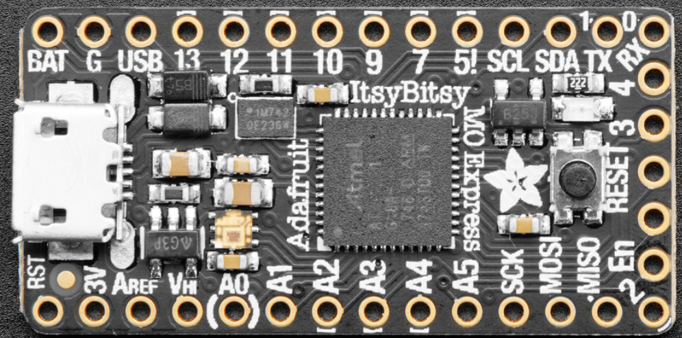
03/18/2019 at 04:07 • 0 commentsI went to the Adafruit website to order another Arduino Feather M0 Express unit to have as a backup. While meandering around their site I stumbled upon a better, smaller, Arduino unit: the Itsy Bitsy M0 Express. The Itsy Bitsy is quite a bit smaller, and almost half the cost of the Feather (so I bought two of them.) It has nearly all of the functionality of the Feather -- even the CircuitPython stuff -- but lacks the battery charging feature. I'm hoping it draws a bit less current too.
Getting it to Fit:
The problem with the Itsy is that the power and battery pins are located at one end of the board and the I2C and digital pins are at the other end. This means that the entire board has to be accommodated within or under the halo motherboard.
![]()
The best solution that I could imagine involved placing the Itsy on top of the motherboard with the USB connector accessible from the right side.
![]()
Not all of the pins are needed -- the analog pins and a lot of other pins related to the battery management or ADC reference. Pins at the corners are required to securely mount the board. There are three mounting holes to secure the motherboard -- two of them underneath the Itsy. There are female headers (two 4-pin and one 14-pin) between the boards so that the Itsy can be removed to gain access to the mounting holes. The headers raise the Itsy about 0.5 inch -- slightly higher than the VL53L0X daughterboards. I'm also thinking that male pin headers could be used instead if the two holes under the Itsy were just alignment pins and the one hole outside the Itsy would have a screw. This approach would lower the height of the Itsy considerably.
Since there is no jack for the battery on the Itsy there are now pads for the battery inputs on the motherboard at the right side. I also added a battery charger (U2 -- MCP73831) to the motherboard. The charge indicator LED is located near the BAT pad. There is not much room to accommodate a disconnect switch for when the battery becomes over discharged -- planning to use a protected cell and hope that it works.
![]()
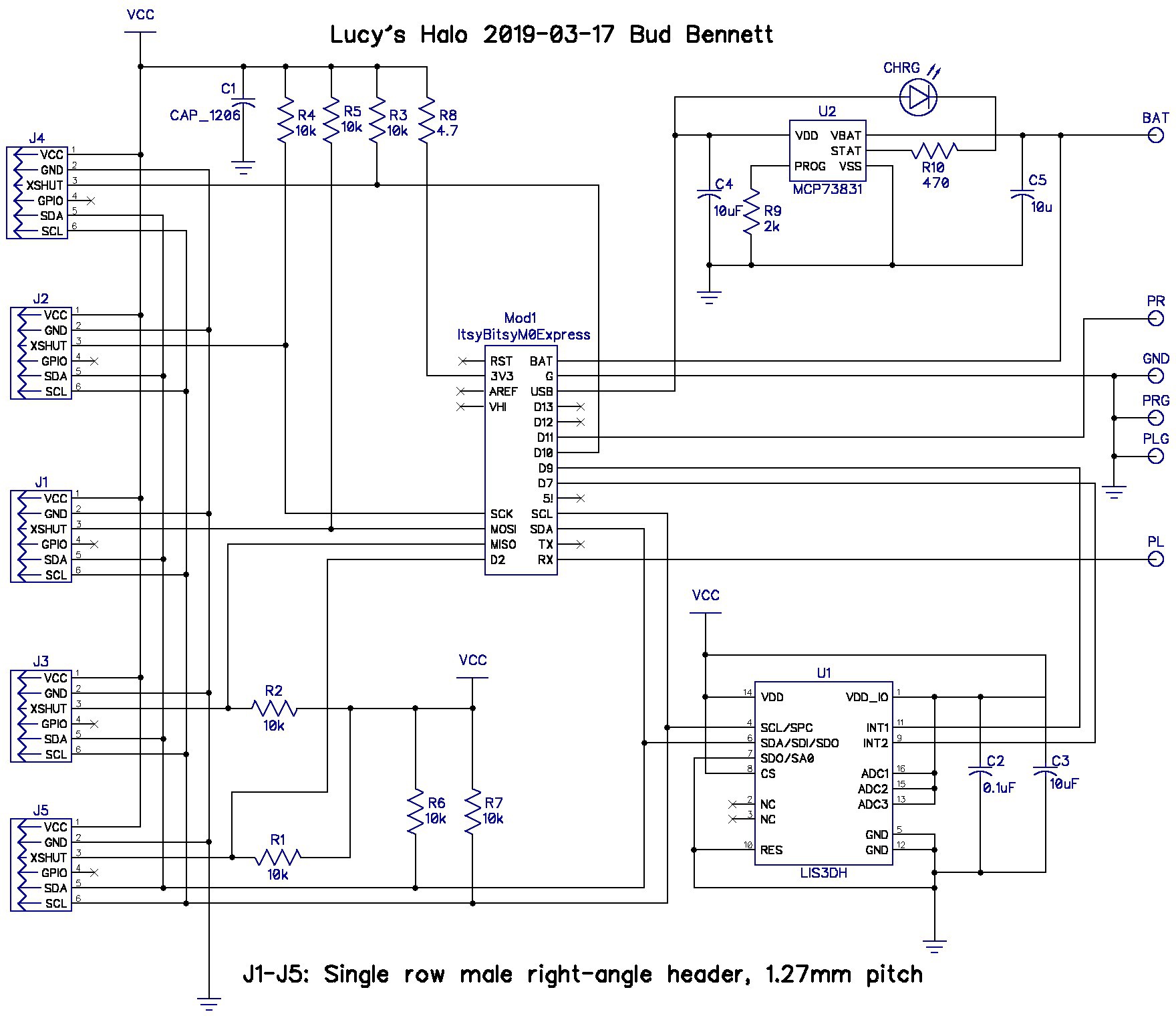
I let the layout guide the schematic.
![]()
The ItsyBitsy is now included on the mother board schematic.
Motion Sensing:
The halo must turn off when Lucy is not moving or if it is tilted to an extreme position indicating that she is sleeping. Therefore I added a simple accelerometer to the system. The LIS3DH should do the job. I wanted to implement a 6-axis motion sensor, but the only one available in CircuitPython is a bit too expensive. This complicates the motherboard assembly since the accelerometer package is a 14-pin QFN. (At least it doesn't have an exposed pad.)
Too Far Too Fast:
I think I'm getting way way ahead of myself with this latest design. The AliExpress sensors are stuck in U.S. customs, so I haven't even been able to test the multiple-sensor capability yet. I will probably just sit on this while the rest of the project catches up to it.
-
Getting Physical
03/13/2019 at 22:27 • 3 commentsWhile I'm waiting for the delivery of the VL53L0X sensor boards from AliExpress, I thought I'd take a whack at understanding the PCB requirements for a first prototype of the halo. The Arduino Feather M0 Express that I got from Adafruit has been working flawlessly. The current drain of the Feather coupled with a VL53L0X sensor board was about 40mA, <20mA for just the Feather, so I thought it worthwhile to explore using the Feather with some custom sensor PCBs as a simple solution (since I only need to make one of these systems).
My first attempt was to just place the AliExpress PCBs into a motherboard that attaches to the Arduino Feather that I ordered from Adafruit. It was huge. The board would be at least 3 inches in width, which might cause Lucy some problems with the fit. I can do better. Therefore, the AliExpress boards will only be used for prototype purposes -- whatever physical arrangement works to prove the concept. I'm planning on using six-pin dupont connectors and gluing the AliExpress boards to a substrate to get the first prototype working. (Or maybe just desoldering the sensors and migrating them to new PCBs.)
Going My Own Way:
By abandoning the AliExpress boards I need to make two sets of PCBs: a daughterboard to contain each VL53L0X sensor and any support circuitry, and a motherboard that attaches to the Feather M0 Express.
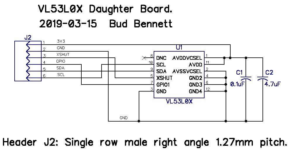
After examining the space requirements of a 0.1" header vs. a 0.05" header, I decided to use the smaller headers to save a lot of space. I ordered a slew of 1.27mm pitch right angle male headers from eBay. Each VL53L0X sensor daughter board only needed the sensor and two capacitors:
![]()
I also decided to use the Arduino 3V3 regulated power supply. This saved many resistors, level translator transistors, and a voltage regulator -- for each daughterboard and the motherboard. The VL53L0X data sheet claims that the part will function without issues with a 3.3V power supply. So be it. The preliminary daughterboard dimensions are 0.35" x 0.4". Pretty small, compared to the AliExpress boards (but not cheaper). The daughterboard attaches to the mother board with 6-pin right-angle headers.
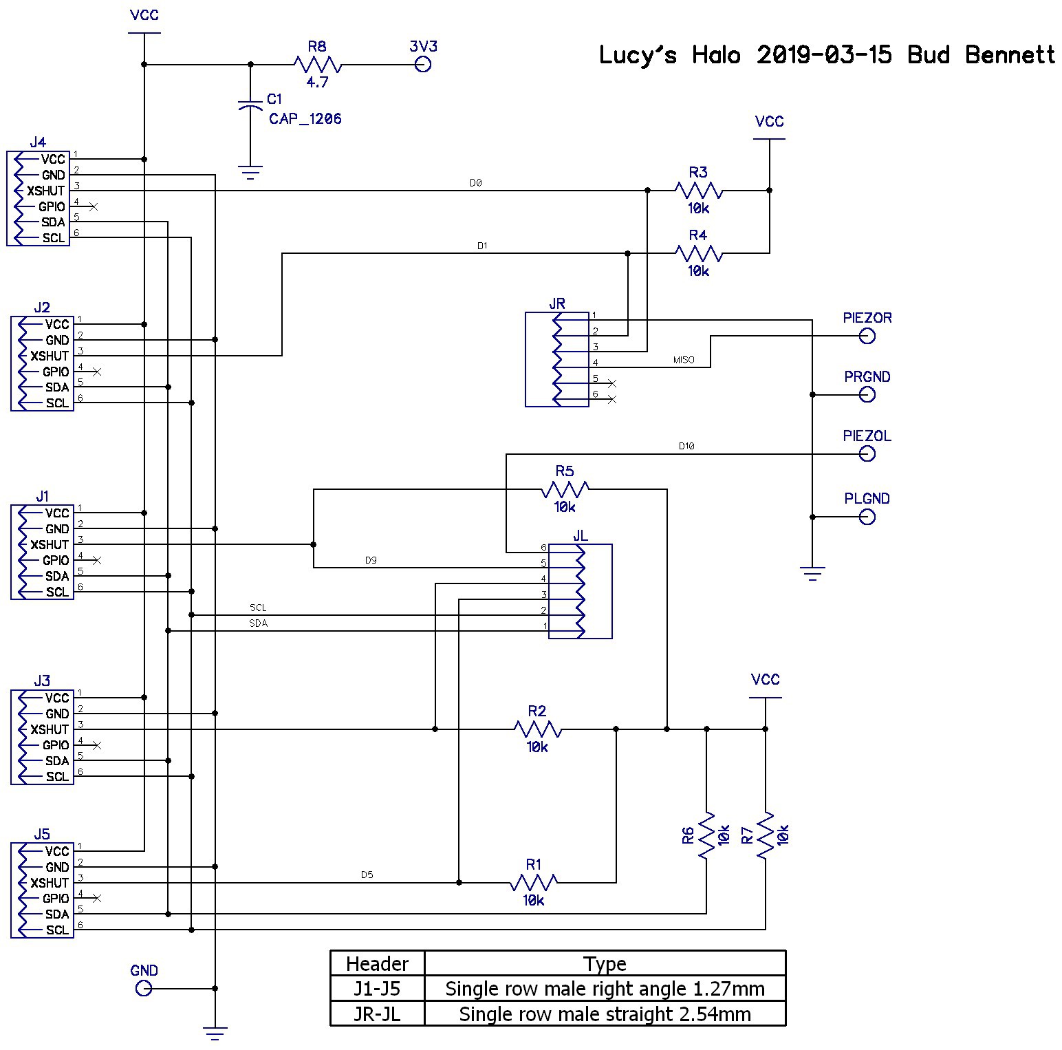
![]()
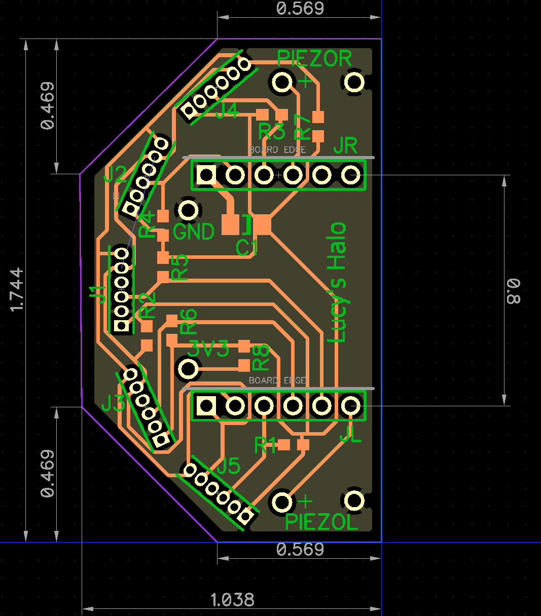
I'm not entirely convinced that all those resistors are necessary. There are placeholders for R8 and C1 -- CYA components. A lot of the pull-up resistors (R1-R5) may be depopulated after the first prototype. After creating the daughterboards I placed them into the motherboard PCB layout to see how big it would be and what challenges popped up. After a few iterations, I settled on the layout below.
![]()
The motherboard plugs into the Arduino using the 6-pin headers spaced 0.8" apart. I also need the Arduino's 3.3V regulated output, which is not available in the first six pins of the header, but Adafruit did provide it as part of a small breadboard area on the Feather M0 Express. Lastly, the two piezo speakers are mounted at the left/right rear of the motherboard -- pretty close to Lucy's ears. (Here's where a couple of resistors in series with the piezo speakers might have been warranted.)
![]()
I tested the assignment of the GPIO with the motherboard header pins -- no issues. Both the daughter boards and mother boards have been ordered. Awaiting delivery of PCBs fro JLCPCB -- check back in one week.
-
Adding Audio Output and Other Stuff
03/11/2019 at 22:47 • 0 commentsMy recent objective is to just get the piezo speakers to respond to changes in distance measured by the VL53L0X sensor. This is mainly a learning exercise for me -- to gain familiarity with the PWM capabilities of a digital output. I'm also attempting to streamline the code. Here's the latest code snippet:
# multiple sensors with PWM speaker outputs
import time

import board
from digitalio import DigitalInOut, Direction
import busio
import pulseio
import adafruit_vl53l0x

# assign pins to VL53L0X shutdown inputs
shutdown = []
shutdown.append(DigitalInOut(board.D5))
shutdown.append(DigitalInOut(board.D6))
shutdown.append(DigitalInOut(board.D9))
shutdown.append(DigitalInOut(board.D10))
shutdown.append(DigitalInOut(board.D11))

# assign PWM pins
piezoL = pulseio.PWMOut(board.D0, frequency=3000, duty_cycle=16000, variable_frequency=True)
piezoR = pulseio.PWMOut(board.D1, frequency=2000, duty_cycle=0, variable_frequency=True)

# turn off all sensors
for n in range(5):
    shutdown[n].direction = Direction.OUTPUT
    shutdown[n].value = False # low is off

# Initialize I2C bus and sensors.
i2c = busio.I2C(board.SCL, board.SDA)

# initialize led
led = DigitalInOut(board.D13)
led.direction = Direction.OUTPUT

# setup multiple VL53L0X sensors
VL53_address =[0x29, 0x2A, 0x2B, 0x2C, 0x2D]
for n in range(5):
    shutdown[n].value = True # turn on sensor
    time.sleep(0.1)
    print("Address = {}".format(VL53_address[n]))
    try:
        while not i2c.try_lock():
            pass
        result = bytearray(1)
        #set new address
        i2c.writeto(0x29, bytes([0x8A, VL53_address[n]]), stop=False)
        time.sleep(0.1)
        # verity new address
        i2c.writeto(VL53_address[n], bytes([0x8A]))
        i2c.readfrom_into(VL53_address[n],result)
        print("device address = {}".format(int.from_bytes(result,'big')))
    except:
        i2c.unlock()
    finally:
        i2c.unlock()

# instantiate all sensors and initialize distance array
VL53L0X = []
distance = []
for n in range(5):
    try:
        VL53L0X.append(adafruit_vl53l0x.VL53L0X(i2c=i2c,address=VL53_address[n], io_timeout_s=0))
        distance.append(1001)
    except:
        VL53L0X.append(None)
        distance.append(1000)

print("distance = {}".format(distance))

# Optionally adjust the measurement timing budget to change speed and accuracy.
# See the example here for more details:
#   https://github.com/pololu/vl53l0x-arduino/blob/master/examples/Single/Single.ino
# For example a higher speed but less accurate timing budget of 20ms:
#vl53.measurement_timing_budget = 20000
# Or a slower but more accurate timing budget of 200ms:
#vl53.measurement_timing_budget = 200000
# The default timing budget is 33ms, a good compromise of speed and accuracy.

def get_distances():
    global distance, VL53L0X
    for n in range(5):
        if VL53L0X[n]:
            distance[n] = VL53L0X[n].range
        else:
            distance[n] = 1000
# Main loop will read the range and print it. PWM Frequency increases with the inverse of distance.
while True:

    if (sum(distance) < 5000):
        print("distance1 = {}".format(distance[1]))
        if (distance[1] != 0):
            piezoL.frequency = int(1000/distance[1] * 300)
            piezoL.duty_cycle = 32768
            led.value = not led.value  # blink LED
        else:
            piezoL.duty_cycle = 0
        get_distances()
        piezoL.duty_cycle = 0
        time.sleep(0.01)
    else:
        led.value = False
        piezoL.duty_cycle = 0
        get_distances()
        time.sleep(0.25)
I still only have one VL53L0X sensor to play with. The main loop just obtains the latest distance measurement from the sensor and changes the PWM output frequency in inverse proportion to the distance. So the piezo speaker frequency increases as the object distance decreases. It works.
Eventually, I'll mix the amplitude between the two piezo speakers to indicate a direction...
Other Stuff:
The other stuff is related to automagically detecting VL53L0X sensors and assigning addresses, and then looping through the sensors to get distance measurements. I'm trying to keep the code relatively compact, so addressing the distance sensors as an array is pretty efficient. If a sensor is not responding, or not populated, the code doesn't care and simply skips it during the measurement process.
I think that I smoked the battery charger on the Feather M0 Express board. I connected a 260mAh HV LiPo battery to the JST connector on the Feather board and noticed magic smoke escaping. I should have checked the pinout documents from Adafruit prior to connecting the battery. It seems that Adafruit decided to reverse the normal positive/negative leads from a battery and, "Did it My Way." I checked the markings on the battery charger IC -- it is a MCP73831. I have a few of these in inventory (doesn't everybody?). I might try to replace the smoked battery charger in the near future.
The misadventure with the battery/charger did not damage the rest of the Feather circuitry. I was able to measure the current drain of the system ( from the USB inputs) as roughly 40mA. If I use a 600mAh 14500 cell, the expected battery life would be about 15 hours. An 18650 cell with 2500mAh would last about 80 hours. Not too bad., but that is for a single sensor --- more sensors = more current.
Bottom Line:
I'm getting closer. Next steps are dependent upon receiving the ordered VL53L0X sensor modules from AliExpress. If they work as intended, then the multiple sensor data needs to be transformed into left and right audio information for direction and distance.
-
CircuitPython Progress
02/28/2019 at 21:15 • 0 commentsThe coding is coming along faster than anticipated. In order to manage the input and output requirements of the sensors and transducers there has to be an understanding of the Arduino's basic I/O capabilities. At a minimum there has to be one I2C interface (2 pins), 5 digital outputs to allow changing of the VL53L0X I2C addresses -- enabling multiple sensors on a single I2C bus, and two PWM digital outputs to generate the audible feedback containing direction and distance.
I tend to write large pieces of code and then get bogged down trying to comprehend what exactly went wrong. This time I just wrote code snippets to get familiar with CircuitPython and the Arduino hardware platform. I'm not using the Arduino IDE -- it is not compatible with CIrcuitPython.
The first objective was to just wiggle the correct digital pins, so I wrote and debugged this code snippet:
import time
import board
from digitalio import DigitalInOut, Direction

# assign pins to VL53L0X shutdown inputs
shutdown = []
shutdown.append(DigitalInOut(board.D5))
shutdown.append(DigitalInOut(board.D6))
shutdown.append(DigitalInOut(board.D9))
shutdown.append(DigitalInOut(board.D10))
shutdown.append(DigitalInOut(board.D11))

for n in range(5):
    shutdown[n].direction = Direction.OUTPUT
    shutdown[n].value = False

while True:
    for n in range(5):
        shutdown[n].value = not shutdown[n].value
    time.sleep(5)
All that this does is wiggle the digital I/O pin on/off every 5 seconds. I was able to put a DVM on the pin and verify that it was behaving correctly.
I then got the PWM outputs to function with this code the generates a 10 Hz square wave on D0 and D1:
import board
import pulseio

# assign PWM pins
oudio_l = pulseio.PWMOut(board.D0, frequency=10, duty_cycle=32768, variable_frequency=True)
audio_r = pulseio.PWMOut(board.D1, frequency=10, duty_cycle=32768, variable_frequency=True)
I got errors trying to assign the PWM outputs to D14 and D15. I took the path of least resistance with D0, and D1. I got correct DC and AC values on both pins with the DVM.
Multiple Sensors
After this initial success, I attempted to implement a method to assign a different I2C address to each VL53L0X sensor. I only have one VL53L0X at this point but that didn't stop me.
This is the algorithm in english:
- Assign pins to I/O.
- Assert the shutdown pins (active low) on all VL53L0X sensors to disable them from communicating on the I2C bus.
- instantiate a generic I2C interface just to assign new addresses to the sensors.
- for each sensor:
- de-assert its shutdown pin to activate the sensor
- send an I2C command over the generic interface to change the I2C address to a unique one.
- read back the I2C address of the sensor as a check.
- leave the sensor active at this point.
- Instantiate the five sensors with unique names and addresses. This will call the calibration procedure and initialize each sensor properly. I commented out all of these instances except the second one in the sequence -- since I have only one sensor.
- Run the main loop using the single sensor. This loop blinks an LED when the distance sensor detects an object. The blink rate starts at 0.5 Hz for distant objects increasing to 10Hz or so for near objects.
Here's the final code that puts all of the above into place.
# multiple sensor simple sensor with PWM speaker outputs
import time
import board
from digitalio import DigitalInOut, Direction
import busio
import pulseio
import adafruit_vl53l0x

# assign pins to VL53L0X shutdown inputs
shutdown = []
shutdown.append(DigitalInOut(board.D5))
shutdown.append(DigitalInOut(board.D6))
shutdown.append(DigitalInOut(board.D9))
shutdown.append(DigitalInOut(board.D10))
shutdown.append(DigitalInOut(board.D11))

# assign PWM pins
oudio_l = pulseio.PWMOut(board.D0, frequency=10, duty_cycle=32768, variable_frequency=True)
audio_r = pulseio.PWMOut(board.D1, frequency=10, duty_cycle=32768, variable_frequency=True)

# turn off all sensors and intialize distance array
distance = []
for n in range(5):
    shutdown[n].direction = Direction.OUTPUT
    shutdown[n].value = False # low is shutdown
    distance.append(1000)

# Initialize I2C bus and sensors.
i2c = busio.I2C(board.SCL, board.SDA)

# initialize led
led = DigitalInOut(board.D13)
led.direction = Direction.OUTPUT

# setup multiple VL53L0X sensors
VL53_address =[0x29, 0x2A, 0x2B, 0x2C, 0x2D]
for n in range(5):
    shutdown[n].value = True # turn on sensor
    time.sleep(0.1)
    print("Address = {}".format(VL53_address[n]))
    try:
        while not i2c.try_lock():
            pass
        result = bytearray(1)
        #set new address
        i2c.writeto(0x29, bytes([0x8A, VL53_address[n]]), stop=False)
        time.sleep(0.1)
        # verity new address
        i2c.writeto(VL53_address[n], bytes([0x8A]))
        i2c.readfrom_into(VL53_address[n],result)
        print("device address = {}".format(int.from_bytes(result,'big')))
    except:
        i2c.unlock()
    finally:
        i2c.unlock()

#VL53L0X_0 = adafruit_vl53l0x.VL53L0X(i2c=i2c,address=VL53_address[0], io_timeout_s=0)
VL53L0X_1 = adafruit_vl53l0x.VL53L0X(i2c=i2c,address=VL53_address[1], io_timeout_s=0)
#VL53L0X_2 = adafruit_vl53l0x.VL53L0X(i2c=i2c,address=VL53_address[2], io_timeout_s=0)
#VL53L0X_3 = adafruit_vl53l0x.VL53L0X(i2c=i2c,address=VL53_address[3], io_timeout_s=0)
#VL53L0X_4 = adafruit_vl53l0x.VL53L0X(i2c=i2c,address=VL53_address[4], io_timeout_s=0)


# Optionally adjust the measurement timing budget to change speed and accuracy.
# See the example here for more details:
#   https://github.com/pololu/vl53l0x-arduino/blob/master/examples/Single/Single.ino
# For example a higher speed but less accurate timing budget of 20ms:
#vl53.measurement_timing_budget = 20000
# Or a slower but more accurate timing budget of 200ms:
#vl53.measurement_timing_budget = 200000
# The default timing budget is 33ms, a good compromise of speed and accuracy.

# Main loop will read the range and blink LED at rate proportional to distance.
while True:
    distance = VL53L0X_1.range
    if (distance < 1000):
        if (led.value):
            led.value = False
        else:
            led.value = True
    else:
        distance = 1000
        led.value = False
    time.sleep(distance/1000)
Debugging with a single sensor was difficult and led down a few dead ends. It took a bit of trial and error to understand what was happening and how to interpret the result.
The second sensor (the only sensor) has its shutdown input connected to D6. Therefore it only responds the second time through the address change loop and has its address changed from 0x29 to 0x2A. After that it stops responding to any address changes since doesn't have the correct address anymore. The sensor can be instantiated as VL53L0X_1 and will operate correctly with the assigned address. This is proven by the blinking LED which changes its blink rate as objects get closer.
Some Griping:
I'm not entirely happy with the reliability of the USB interface between my iMac and the Arduino board. For no apparent reason the CIRCUITPY drive icon disappears from my iMac's desktop and the Arduino board reboots and reloads the CircuitPython code. Flakey.
Onward:
My swelling confidence that things were working out led me to make a couple more purchases:
Some piezo speakers from Amazon.
Six more VL53L0X distance sensors this time from AliExpress (sorry Adafruit, my loyalty has limits.) These 6 boards cost less, including shipping, than the single board from Adafruit. In fact, the board is less than 1/2 the price of a bare VL53L0X sensor from Digikey. Go figure.
-
A Working Sensor
02/27/2019 at 19:21 • 0 commentsI ordered a VL51L0X sensor breakout board and an Arduino Feather M0 Express from Adafruit. The Feather is attractive to me because of its inherent CircuitPython capabilities. I probably paid the highest prices for these items, but -- considering the support and the initial development of the sensor interface -- it is worth it. Soldering the pins onto the two boards took no time at all. After that I just plugged them into a half proto-board:
![]() I got into trouble immediately by not being familiar with the Arduino IDE and methodology. I overwrote the existing CircuitPython data with some C code for the VL53L0X. It took me about an hour to get the Arduino to report distance from the sensor. But after that I would have to learn to program in C to go any further. (One of these days I'll learn C.)
I got into trouble immediately by not being familiar with the Arduino IDE and methodology. I overwrote the existing CircuitPython data with some C code for the VL53L0X. It took me about an hour to get the Arduino to report distance from the sensor. But after that I would have to learn to program in C to go any further. (One of these days I'll learn C.)This morning I discovered that there was an existing VL53L0X python library that ran under CircuitPython. I then reinstalled the CircuitPython capabilities and spent an inordinate amount of trial and error time learning to get the simple sensor interface working. I finally got a stream of data out of a terminal program on the iMac.
![]()
Anecdotal Data:
The beam width is just as small as the data sheet says -- about ±12°. As the distance to the object increases, the size of the object must increase as well. It would not detect my hand at 800mm but would detect a sheet of 8.5x11 white paper. So it seems that five sensors will be a good starting number to get the required beam width.
Next steps involve learning the sensor command interface, experimenting with time/accuracy tradeoffs, reassigning the sensor's I2C address, and getting familiar with the CircuitPython libraries for GPIO and PWM. I also need perform some experiments with detecting objects of different reflective properties and the sensors resistance to ambient light. Lots of work left.
-
Thinking Out Loud
02/19/2019 at 23:30 • 2 commentsLocation:
I've had a couple of days to think about this project. I've also been observing Lucy when she's out and about to determine the best location for the halo. Lucy tends to walk with her head lowered, so it seems the best place to put a smallish electronics package is on her forehead between her eyes and ears. She has about 50mm to work with. This location would not have any obstructions from Lucy's other body parts and could be secured with a simple strap around her head. I think that I'm being overly simplistic here, but my expertise is not with mechanical things.
Choosing a Sensor:
There is a whole universe of distance sensors out there. I've ruled out certain types for size, power consumption, or aesthetic reasons. The favorite so far is ST's VL530X ToF (LIDAR?) distance sensor, for the following reasons:
- It's tiny. (4.4x2.4x1.0 mm)
- Low power drain: 20mW avg.
- Low component count.
- Good Range: 5-200cm
- More accuracy than needed: < 5mm.
- Fast: 33ms acquisition time.
- I2C interface. (This is both good and bad...details below.)
What's not to like:
- Narrow field of view: 25°. (Multiple sensors required to cover adequate field of view.)
- The data sheet sucks. ST has decided not to include a table of registers addresses for the I2C interface. (Details below.)
- Extremely complicated to implement if you're not expert in C or compilers or the jargon of embedded processors.
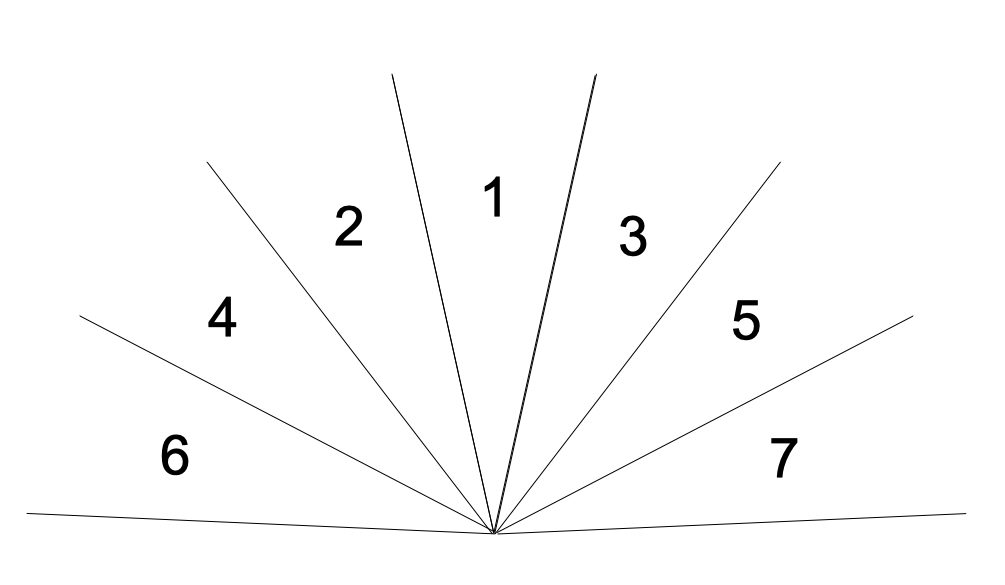
Field of view:
The VL530X has a field of view, per the datasheet, of 25°. This is pretty narrow. I put together a simple diagram to aid in determining the number of sensors required for this application:
![]() I believe that the minimum number is 5. It's possible that 3 would work, given that Lucy is most likely to collide with something directly in front of her and her head is swiveling to match forward direction. Any comments on this? More sensors mean higher power requirements and shorter battery life (and higher cost -- the sensor is about $6).
I believe that the minimum number is 5. It's possible that 3 would work, given that Lucy is most likely to collide with something directly in front of her and her head is swiveling to match forward direction. Any comments on this? More sensors mean higher power requirements and shorter battery life (and higher cost -- the sensor is about $6).The Interface:
I like the I2C interface. It's a standard. Some aspects difficult to implement and many components don't comply with all aspects. But the problem here is that ST has not properly documented how to use this sensor. There is not a word about the registers that can be addressed or what they do. ST requires the prospective customer to use their API (written in C) as the only method of communicating with the sensor. This sucks badly.
I found that Pololu offers a reasonably priced breakout board for this sensor, and also provides a library of commands that work with the Arduino. I've never messed with Arduino, so this is still a bit intimidating. But this is probably the path I'll choose going forward. I've asked a friend who's familiar with Arduino for help.
Other Features:
- Battery and charger. Probably a single cell Li-Ion battery. An 18650 cell contains quite a bit of energy. Charge from USB port.
- Power supply: 3.0V switcher. Or LDO with a 3.3V switch mode converter for efficiency.
- Accelerometer. To turn off the unit if Lucy is not moving or is laying on her side sleeping. A power saving feature.
That's all I've got so far. I'm sure a lot of this will change as things progress.
 I got into trouble immediately by not being familiar with the Arduino IDE and methodology. I overwrote the existing CircuitPython data with some C code for the VL53L0X. It took me about an hour to get the Arduino to report distance from the sensor. But after that I would have to learn to program in C to go any further. (One of these days I'll learn C.)
 I believe that the minimum number is 5. It's possible that 3 would work, given that Lucy is most likely to collide with something directly in front of her and her head is swiveling to match forward direction. Any comments on this? More sensors mean higher power requirements and shorter battery life (and higher cost -- the sensor is about $6).