 Connor Yamada
-
1Step 1
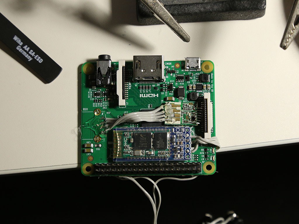
I started by trying to package the peripherals as tightly as possible on the Pi. The largest obstacle was the USB WiFi adapter, which stuck out quite a bit more than everything else. I removed the USB jack with some side cutters and my iron and attached ribbon cable to the exposed data and power lines. I then removed the WiFi adapter from its plastic case and soldered the wires directly to its board. Next, I hot glued the Bluetooth module to the top of the Pi and ran more ribbon cable to the headers underneath. I also attached the two pushbuttons with slightly longer pieces of cable.
![]()
-
2Step 2
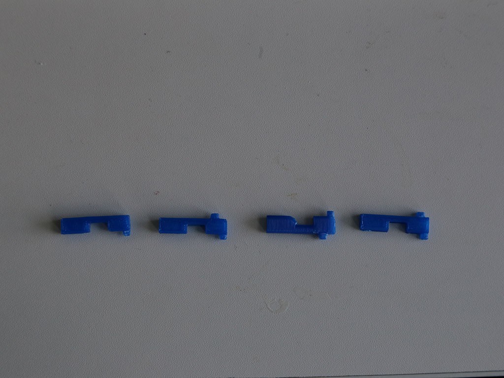
Space was already pretty tight and I still needed to attach the LiPo charger/booster. I did some quick measurements and printed out a support for the board. Took a few tries to get it right.
![]()
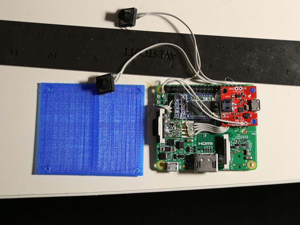
With everything mounted on the Pi, I printed off a quick base to see if my measurements lined up.
![]()
-
3Step 3
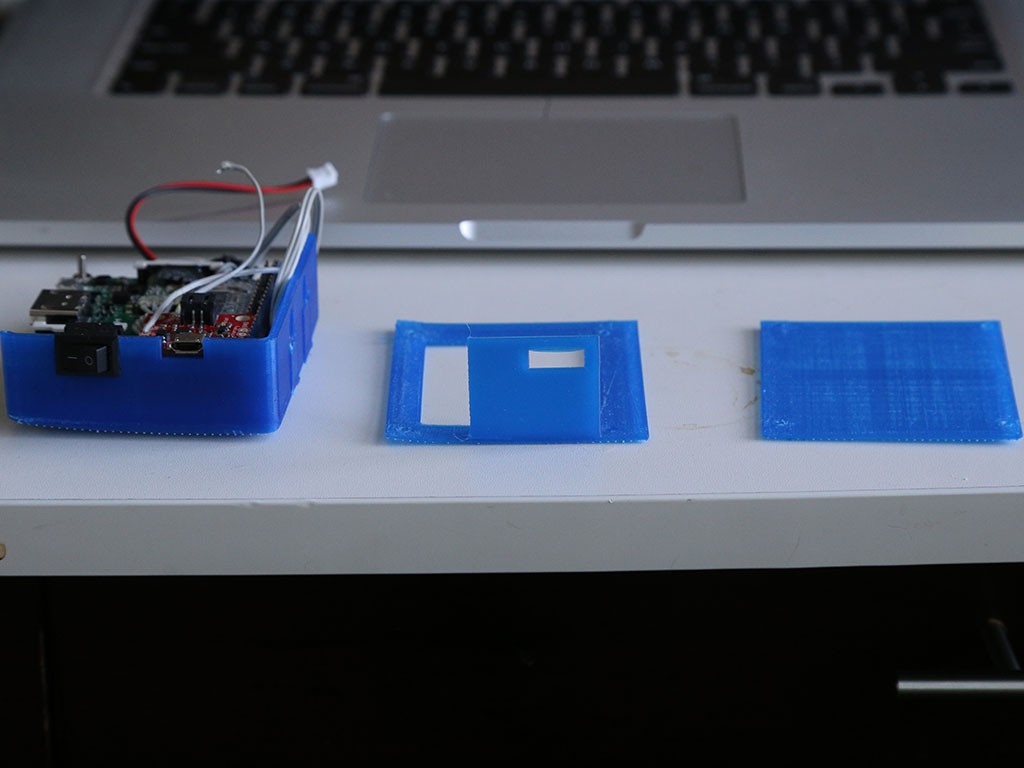
I now had a pretty good idea what the final x and y dimensions were going to be. I wanted to keep the camera as close to the size of the Pi as possible, which meant the large battery had to fit snugly underneath the bottom of the Pi. I printed out a few spacers so that the LiPo wouldn’t get punctured by any of the protruding headers. After that I printed off a few more test pieces to make sure that the Pi, battery, charging port, buttons, and switch would fit.
![]() More test prints.
More test prints.![]()
A cutaway of the case (saves time and printing material!)
Everything lined up.![]()
-
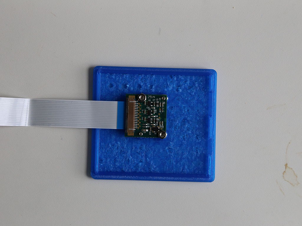
4Step 4
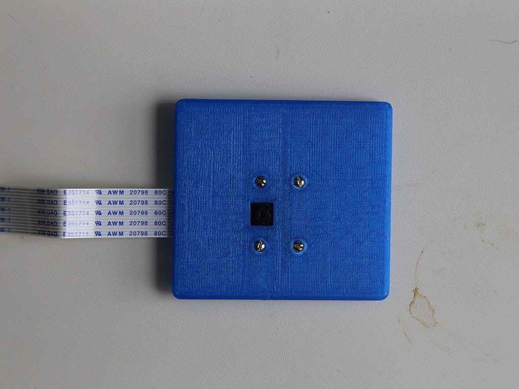
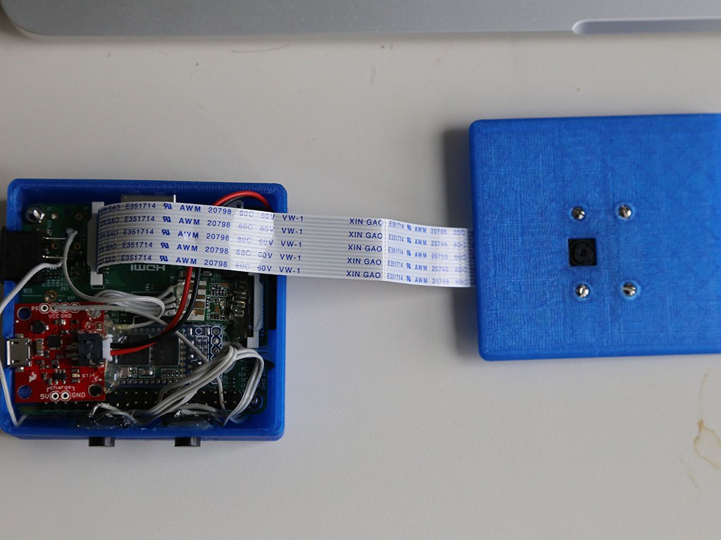
With the bottom of the case completed, I now had to figure out a way to mount the camera module to the top. The previous camera case I had used tension to hold the camera via its four mounting holes however, I wanted something a little more secure. I designed platforms for the camera board to rest on which held the board in place with screws.
Recessed the screw on the front![]()
![]()
-
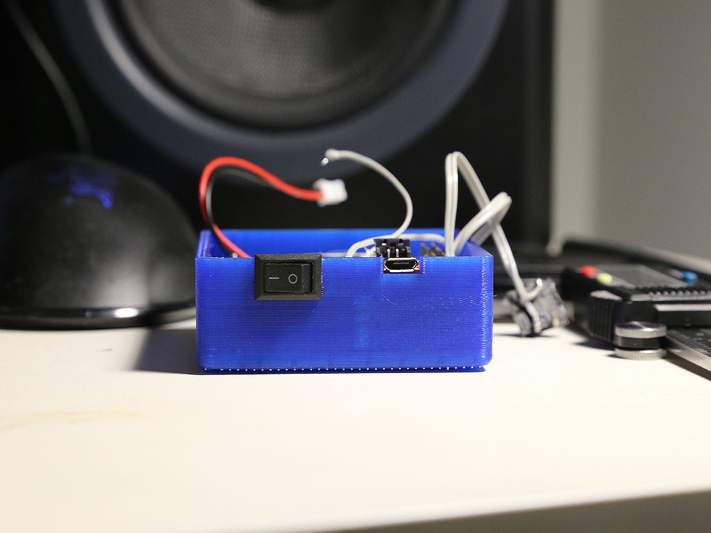
5Step 5
The last step is putting the two halves together!
![]()
![]()
Raspberry Pi Action Cam
A video and still camera based on the Raspberry Pi A+. The camera has integrated bluetooth and wifi for file transfers, as well as an on-boa
 More test prints.
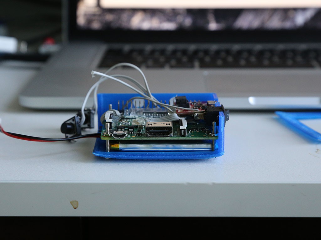

Discussions
Become a Hackaday.io Member
Create an account to leave a comment. Already have an account? Log In.