Close
0%
0%

Design and Build a Companion Robot for MS Care

The project aims to design and build a companion robot for aid in primary and secondary progressive Multiple Sclerosis care.
Similar projects worth following
The companion robot will provide multiple functions including biomechanical movement, heart rate measurement and visualisation and automatic 999 calling. This will involve software design, programming, 3D printing, electronics and mechanical engineering to provide a fully working prototype.

The instructions and information for this project will be presented as project logs. Information will also be available in the form of files and pictures to aid mechanical and software development. Feel free to ask questions in the discussion and highlight areas where more information is required. The project is being featured at the OER19 conference https://oer19.oerconf.org/news/guest-blog-adding-to-the-open-ecosystem-open-source-hardware-by-beverly-gibbs/

guistart.py

x-python-script - 2.51 kB - 03/18/2019 at 12:05

Download

example.py

x-python-script - 287.00 bytes - 03/18/2019 at 12:04

Download

pulsesensor.py

x-python-script - 5.16 kB - 03/18/2019 at 12:04

Download

MCP3008.py

x-python-script - 766.00 bytes - 03/18/2019 at 12:04

Download

board .dxf

AutoCAD DXF - 2.27 kB - 03/11/2019 at 19:27

Download

View all 7 files

  • 1 × Raspberry Pi
  • 1 × servo
  • 1 × 3D printed components
  • 1 × 7" touch screen
  • 1 × Pulse Sensor

View all 9 components

  • Touch feedback

    joshastley104/03/2019 at 12:10 0 comments

    Once the companion robot was assembled i had the idea of adding a touch feedback element. this low cost solution allows patients to rub their finger against two different grains of sand paper and monitor how this feeling can change over time. Loss of sensation can be an early indicator of a MS episode and this low cost solution provides some feedback on how this changes.

  • Final Assembly

    joshastley103/27/2019 at 14:53 0 comments

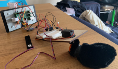
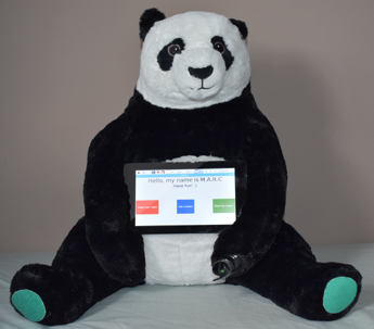
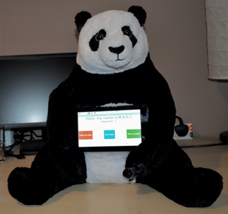
    Once the internal assembly is working and tested it can be inserted into the 'skin'. This proved a challenge and, in my case, is not perfect. The final output is functional and serves as a prototype proof of concept of what can be done with minimal experience and cheap components. The pulsesensor was attached to the paw of the companion robot and the screen sits on the chest of the companion robot secured by connections to the arms of the panda. 

  • Assembly

    joshastley103/27/2019 at 14:50 0 comments

    The initial part of the assembly attaches all the components we've used before to a laser cut board. This is completely decided by the internal structure of the 'skin' used and the space available to work with. The hardware is then screwed on to the board and wire extensions added. Much of this centres around tinkering and aesthetic appeal. for example a used fabric glue and electrical tape to attach fur over the mechanical tail and wrap wires together.  

  • GUI

    joshastley103/27/2019 at 14:45 0 comments

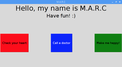
    This project uses a basic GUI aimed at proving concept feasibility compared with actual usage. As a mechanical engineer by trade developing a commercially viable GUI is probably out of my wheelhouse so instead I settle with functional. the GUI screen allows the user to interact with 3 large simple buttons to enact the three different functions. Code will be found in the finalgui.py posted in the file log.

    M.A.R.C refers to the Medically Aided Robotic Companion (yes I named him!)

  • Automatic calling - Twilio

    joshastley103/27/2019 at 14:42 0 comments

    The automatic calling function is facilitated by an online service called Twilio. Multiple similar services are available and most provide tutorials on how to make outbound calls. for this project I use only outbound calls so a trial account is sufficient however if you wish to receive calls and send multiple calls then a full account is required. The companion robot can be customised to say whatever is desired and is something that can be developed in-conjunction with patients needs.

  • PulseSensor

    joshastley103/27/2019 at 14:38 0 comments

    The code for the pulsesensor draws on https://tutorials-raspberrypi.com/raspberry-pi-heartbeat-pulse-measuring/. The code is amended to provide use with the specific hardware used in this project and can be found as a file in this project. In addition a line of code was added to save the data as a csv file and a second python script to convert this csv into excel. Data visualisation tools are available however for this project is appropriate for doctors to have access to this sensor data retrospectively.

  • MCP3008 vs ADS1015

    joshastley103/18/2019 at 12:04 0 comments

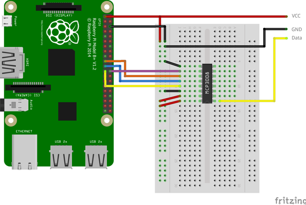
    A transformer is required to convert the analog pulse signal to a digital signal since the raspberry pi has no analog pins. I tried two different connections. 

    • ADS1015 connected to GPIO pins
    • MCP3008 connected to SPI pins in Spi-Dev library

    I found that the second configuration was much easier to code for and overall more accurate. I compared the pulse values to those given by a garmin smartwatch. using GPIO pins the pulse varied wildly and gave a value of 138BPM compared to the gramins value of 78BPM. Using the SPI library The pulse was measured at 78BPM compared to 72BPM by the smartwatch. This is within the standard tolerances used in portable heart rate monitors at a commercial level.

    The code and wiring diagram can be found in the file log and instructions.

  • Attaching the screen

    joshastley103/12/2019 at 19:31 0 comments

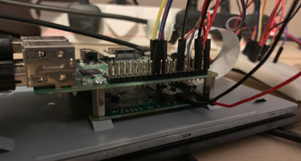
    The 7" touchscreen is a specially designed raspberry pi accessory. the Pi fits directly onto the back of the screen. The screen requires two GPIO pin connections and feeding the display tape into the raspberry Pi. set up is simple and then you can begin using the touchscreen.

  • Rechargeable battery

    joshastley103/11/2019 at 20:38 0 comments

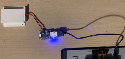
    The battery use din this project is a LiPo 850mAh. it is connected to a Adafruit PowerBoost 1000C. The battery cable directly connects to the powerboost which in turn connects via USB - MicroUSB to the Raspberry Pi. The USB adapter comes with the powerboost however it will need to be soldered to the Adafruit before use. The battery and rechargeable board will need to be charged.

  • Battery holder

    joshastley103/11/2019 at 20:33 0 comments

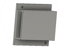
    The battery is encased in a 3D printed holder. This prevents leakage and also provides extra fireproofing in case of an incident. The battery holder is found as an .stl file in this project. 

View all 15 project logs

  • 1
    MCP3008 connection

View all instructions

Enjoy this project?

Share

Discussions

Trois C Ainsley wrote 03/14/2019 at 22:01 point

cool project, can’t wait to see the result!

  Are you sure? yes | no

Alexander wrote 03/09/2019 at 17:31 point

Very neat idea -- there is a lot of research and testing going on in this space at the moment. One problem area that some research suggests might hinder adoption of this type of technology is charging. People who are elderly or who have movement difficulties can find it very difficult to a) remember to charge a device and b) find the charge port, and connect it. Many designs are moving to Qi wireless charging or something equally easy to use. 

I really hope to see your project come to completion! Will be keeping an eye out.

Cheers!

  Are you sure? yes | no

joshastley1 wrote 03/11/2019 at 19:31 point

Interesting idea! Charging definitely is an issue and unfortunately will not be in the scope of this project. Many current companion robots are used in conjunction with conventional care. Hence carers, who may visit less frequently due to the companion robot, can make sure the device is charged for the patient.

  Are you sure? yes | no

Dusan Petrovic wrote 03/08/2019 at 17:18 point

I love the idea! Could you please document your work progress!

  Are you sure? yes | no

Similar Projects

Does this project spark your interest?

Become a member to follow this project and never miss any updates