-
1Basics
Hey whats up Guys! Akarsh here from CETech.
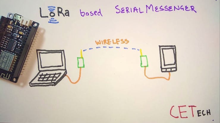
Today we are going to make a project which can be connected to your smartphone or any computer and it makes that device LoRa enabled messenger. Now when that will be done you would be able to message any other device using the same LoRa messenger. This all is done without presence of 4G/LTE/3G/GSM/WiFi/SMS.
![]()
Lets start with the project now
-
2Parts
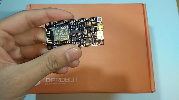
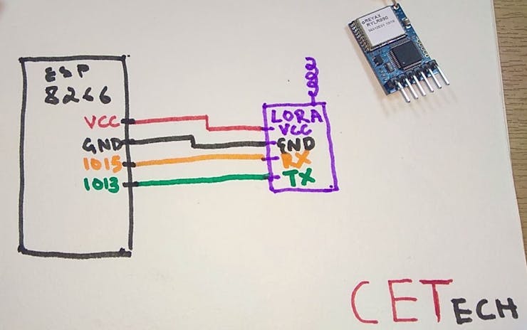
To make this you will need an ESP8266 board, I suggest to use a NodeMCU style board, I used Firebeetle board from DFRobot as it has on board battery charging and monitoring solution.
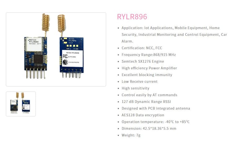
For the LoRa purpose I used a RYLR896. I highly suggest this module as it is very easy to use over UART using AT commands.
I would also recommend using a PCB to make the project so that adding battery/OLED display/switch/esp8266 doesnt remain difficult. You can order your PCBs from PCBWAY as they offer 10 PCBs for just 5$. Check out their online Gerber viewer function.
![]()
The Firebeetle board ESP8266
![]()
-
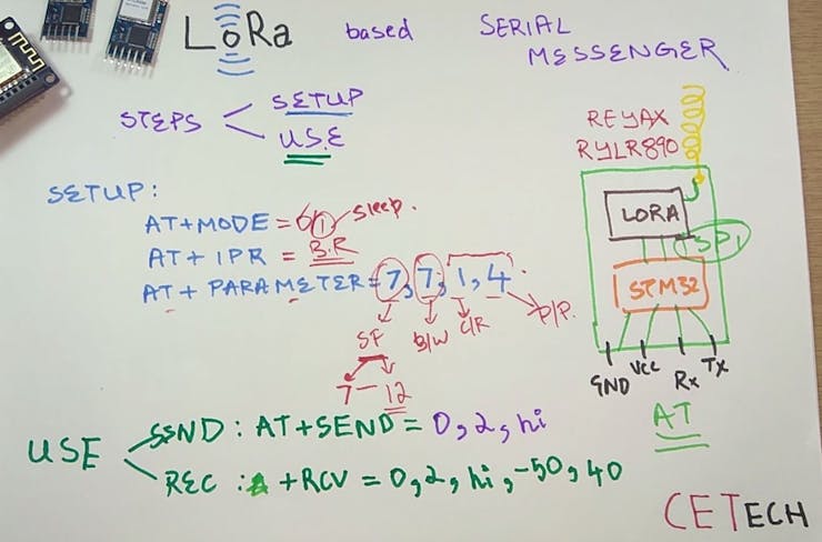
3Understanding the Reyax Module and how to use it. (OPTIONAL : you may skip reading this step if not interested about the working)
1. The LoRa module we have is a UART module which is configured using AT commands.
![]()
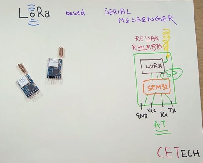
2. The module houses a STM32 MCU which does all the talking to the SPI LoRa module onboard the RYLR896.
![]()
3. The commands in the picture are basic ones you may refer to this document for more: REYAX-Lora-AT-COMMAND-GUIDE
4. I still strongly recommend you to go through my YouTube video where I explain this properly.
-
5Download and setup the Arduino IDE
Download the Arduino IDE from here
1. Install the Arduino IDE and open it.
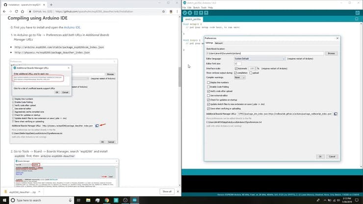
2. Go to File > Preferences
![]()
3. Add http://arduino.esp8266.com/stable/package_esp8266com_index.jsonto the Additional Boards Manager URLs.
4. Go to Tools > Board > Boards Manager
5. Search for esp8266 and then install the board.
6. Restart the IDE.
-
6Coding the project
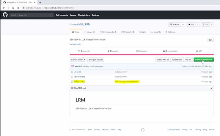
1. Download the repository: https://github.com/akarsh98/LRM
![]()
2. Extract the downloaded folder and open Stagei.ino file in arduino IDE.
3. Navigate to Tools > Board. Select the appropriate board that you are using NodeMCU(12E) works in most of the cases.
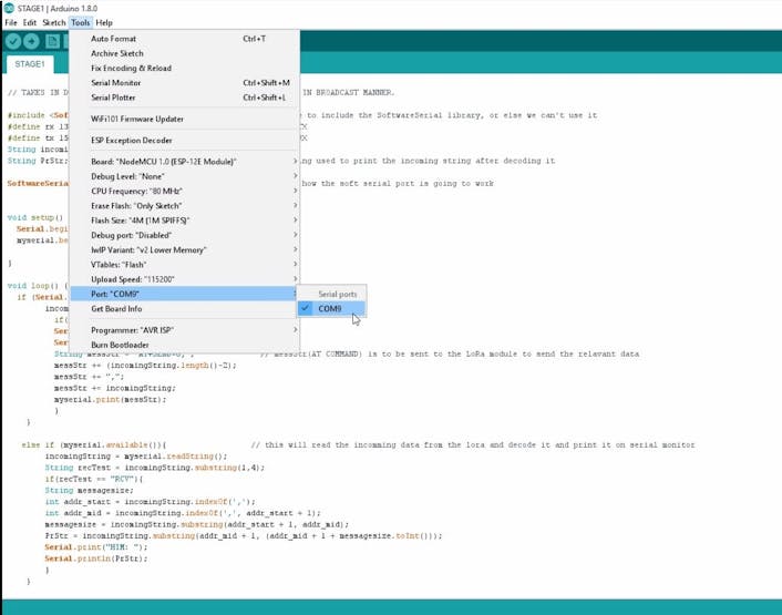
4. Select the correct comm. port by going to Tools > Port.
5. Hit the upload button.
6. When the tab says Done Uploading you are ready to use the device.
![]()
After uploading open the serial monitor to view the following details
-
7Playing with the device
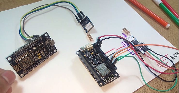
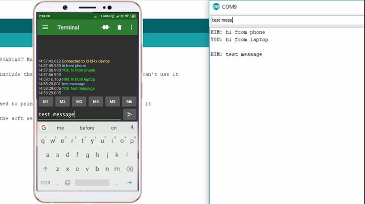
1. Connect the devices using USB cables to two different devices on which you need to do the messaging from. In my case I connected one module to my laptop and the other one to my phone using OTG cable.
2. Move over to the serial monitor and start texing instantly!
![]()
3. CONGO! the device is working as expected.
LoRa Messenger for two devices for distance up to
Connect the project to your laptop or phone and then chat between the devices without internet or SMS using just LoRa. Serial terminal based
Discussions
Become a Hackaday.io Member
Create an account to leave a comment. Already have an account? Log In.
Could this conceivably used with something like Z-Modem to create a full ANSI TUI like the old BBS's from the 1980s/now?
(Asking for a friend) 😀
Are you sure? yes | no
what distance have you achieved? What are your line of sight conditions like?
Are you sure? yes | no