-
Current state of prototype printer
01/06/2024 at 07:12 • 0 commentsCurrently the prototype can produce prints, but there are serious defects in the motion system. Most notably, the pinion gears do not stay still on the stepper motor shafts. This inconsistent wobble distorts print lines, especially when travelling diagonally. Here's a video of the x-y gantry in motion.
Hard to see the wobble here, but it was quite apparent in the first few test prints, and became worse with time.
To fix this, I'm going to reduce the size of the pinion gear and lasercut a series of these gears with varying internal diameter. I cant easily control the kerf-width of the lasercutter (at least down to the tolerance needed for a press fit), but a rough estimate would be ~0.3mm. To cover this range, I'll lasercut a series of gears with ID 5mm +- 0.3, 0.2, 0.1 and see what fits. Should get around to it in a day or two. :)
-
Creating custom functions in Marlin
08/02/2019 at 16:51 • 2 commentsThis log will be both a description of how the backlash determination function is called in Marlin, and a brief tutorial on how to run your own functions using gcode commands.
First, lets go over how the backlash determination function, M954, is called.
All gcode functions in Marlin must have two pieces, both located in Marlin_main.cpp;
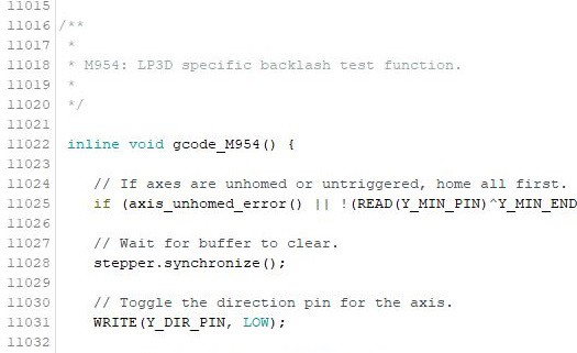
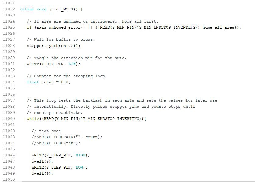
The function definition, which is of the form, "inline void gcode_(your gcode number)":
![]()
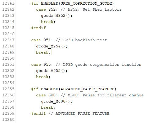
And a case for your specific gcode number, which looks like this:
![]()
When the printer receives a gcode command, its case is called by the parser, and the gcode command in the case is run. This is how all gcode commands are run. Therefore to run my own function, I chose an unused M-code, M954, and created a case and function definition using that number. Now when the printer receives "M954", the backlash determination function is run.
To call the function from an LCD, you must create a menu item in ultralcd.cpp that sends the printer your chosen gcode. Thankfully, there are macros in Marlin that make this very easy, and all you have to do is place 1 line in the right place. The syntax is described below.
ultralcd.cpp contains the LCD menu tree for Marlin, eg. the main menu, prepare menu, control menu etc. Each section is denoted by a small header:
![]()
![]()
If you would like to place your new menu item in the prepare menu for example, you must place your menu item below this header. Menu items that call gcode functions are structured like this:
MENU_ITEM( gcode, "name of your item", PSTR("your gcode number") );
The name you would like to appear on the LCD goes in "name of your item", and your gcode number goes in quotations inside of PSTR(). This will create a menu item that, when selected, sends the printer your chosen gcode number.
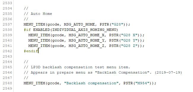
Below you can see a portion of the prepare submenu:
![]()
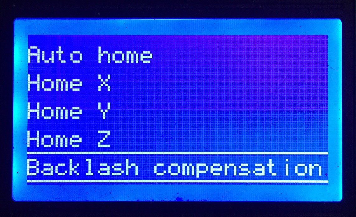
I wanted my function to appear in the prepare menu below the auto home section, so I found the prepare sub menu at line 2514, scrolled down to find the "Auto Home" menu item at line 2537, and placed my new menu item below this. This created a new menu item in the LCD below the homing items:
![]()
Now when I select Backlash compensation from the LCD, the printer receives "M954". :)
A quick recap on creating your own functions:
1) Go to the top of Marlin_main.cpp, and find an unused M-code. There are quite a few around ~M900.
2) Create a function definition in Marlin_main.cpp around line 11000, in the form, "inline void gcode_M(your chosen gcode number)"
3) Create a case for your function around line 12300, in the form found above.
4) If you would like to create an LCD item for your function, create a new menu item in the form:
MENU_ITEM( gcode, "name of your item", PSTR("your gcode number") );
in ultralcd.cpp, and place it where you would like your new item to appear.
And now you can run whatever you want! Errors may still appear on compilation, but this will hopefully help you get past most of them.
Thanks for reading! The next update will be on re-writing gcode files to compensate for the backlash in each axis. I've posted my python script that accomplishes this, and I'll be transferring that code into C++.
-
Automatic backlash determination
07/31/2019 at 19:46 • 0 commentsI'm just finishing up travelling for the summer and I've been slowly testing new code while I can. As of a couple days ago, I've finished the automatic backlash determination function and have it running as a gcode function in Marlin.
The goal of this piece of code is to use the endstops on the printer to automatically determine the backlash in each axis. To do this, the printer first homes itself so that the given carriage to test is pressing into its endstop switch. It then steps the carriage the opposite direction and counts how many steps it takes to deactivate the endstop. It is theoretically a very simple piece of code, just a "G28" (home all axes) call and a while loop to step each axis and count, but Marlin has a timeout safety feature that restarts the printer if the main control loop is interrupted for more than ~5 seconds.
It took quite a bit of trial and error to find a solution, but it turns out that if you wrap your function in an unused gcode name, M954 in my case, the main control loop will allow your function to run until completion. This is what I ended up using, and as a handy side effect, it also makes it very easy to add any other function into Marlin. I'll put out a short tutorial in my next update on how to add your own functions into Marlin, and what I've had to lookout for while building mine.
Here's the backlash determination function in its current state:
![]()
![]()
First I'll go through the function itself and what it outputs, and then I'll go through how it is called in a second update when I have the time.
When the printer receives "M954", the function first checks if the axes haven't been homed, or if any of the endstops aren't triggered. If either is true, it then homes the axes. This ensures when the rest of the program runs that the carriages are in position to be tested. Currently, the code is only configured to run the Y axis, but the final code will simply loop the entire function over each axis.
"stepper.synchronize()" then tells the printer to wait for all moves in the buffer to clear before continuing. This means that if the printer is still moving, the function won't continue past this line until everything's done. This prevents functions from stepping on eachother.
"WRITE(Y_DIR_PIN, LOW)" then writes a low value to the Y axis drivers direction pin, making the stepper turn in the opposite direction that it homed. WRITE(...) is part of the fastio.h library in Marlin, which is an extremely useful for tool for directly controlling or reading the output of pins on your printers control board. For anybody else trying to write functions for Marlin, fastio.h is very much your friend. (READ(pin) is also from fastio.h)
Now that the axis is safely homed and prepared to be stepped in the right direction, the while loop will begin to step the given axis forward until, "READ(Y_MIN_PIN)" returns 0, eg. the endstop deactivates. When complete, the step direction pin is then returned to HIGH.
The counted steps are then divided by the axis steps/mm, given by planner.axis_steps_per_mm[Y_AXIS], finally yielding a backlash in mm. For the time being, the backlash is simply echoed over serial, but in the final iteration the code will set values to be used by the backlash compensation function, which I described in the previous update.
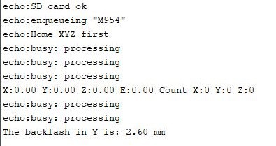
The final output from the arduino serial monitor looks like this:
![]()
:)
How accurate the function is remains to be seen, but the 2.6mm value is relatively close to the 2.3mm I've been measuring by hand. The extra distance looks like it's coming from the endstops themselves, as due to their internal switch mechanism, there is some "give" before the endstop releases after it is pressed. This distance should be relatively consistent between endstops of the same model, so dealing with it in code should be simple enough. I'll get around to accurately measuring it when I can. Updates on that later.
I should also note that this code is not at all generalized for different printer configurations, and running this on a delta machine or core-xy could seriously damage or misalign your printer. My level of Marlin knowledge is not far along enough to write safe code for anything other than cartesian machines, so a more advanced Marlin-er will need to take up the challenge before anything can be integrated into released code.
Thanks for reading! The next update should be quick.
-
Backlash compensation algorithm running
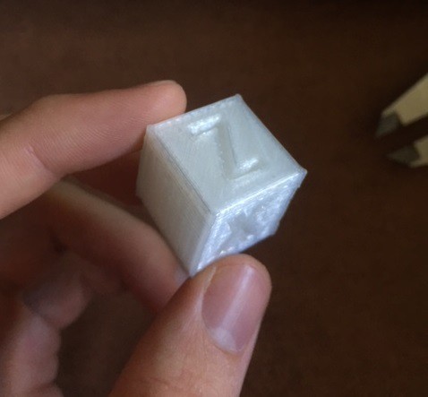
05/19/2019 at 03:19 • 1 commentThere's been a huge improvement in print quality since I got the backlash compensation algorithm running. Test print number 8-ish looks pretty good! I'd caution even acceptable.
![]()
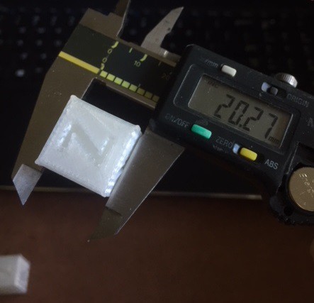
![]()
The y-axis is now much closer to 20mm than without compensation, so I'd say that the algorithm is working!
The backlash compensation software isn't actually too complicated. It's just a python script that I run the gcode files through before printing, and it adds quick G0 moves that take up the backlash before every direction change. Right now it is a separate program from the printers software, but in the next update I'll be dealing with placing it inside Marlin 1.1.9 to run before every print.
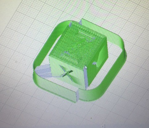
The compensation moves can be seen if you load the altered gcode files in Pronterface.
![]()
In the picture above, that 'split' in the line around the cube is due to the compensation moves that the script added. Here the script is only running for the Y axis, as the backlash in the X and Z axis is unnoticeable. But if the other two axis had significant backlash, we would see similar splits on the left and right sides as well as the front and back. For context, the backlash in the Y axis is ~2.3mm and the backlash in the X axis is ~0.2mm.
I should add that the Y axis only has this much backlash because I've put off upgrading the Y axis rack and pinion to test the compensation. Once I've finished testing I'll install the new rack and pinion and the backlash will be much closer to the ~0.2mm of the X and Z axis.
Now here's how the compensation algorithm works:
To determine the amount of backlash in each axis, I measured the backlash in each axis and entered the measured values before running the script. In the next update, I'll be dealing with using the endstops to determine these values instead.
Once we have the backlash values, we need to determine where to place our compensation moves. To do this, the script splits the gcode files into three lists; all lines containing X moves, all Y moves, and all Z moves. It then iterates through each of these lists and determines the direction of the printhead at each line. To do this, the script compares concurrent pairs of moves, subtracting the current position from the last position and storing the sign of the remainder. ( either +1 or -1 )
This creates three new lists with a negative or positive value for each line. The script then iterates through these three new lists and compares pairs of lines. If the sign of the current line differs from the sign of the next line, that means the printhead has switched direction at that line.
For example, if the list was, [ +1, +1, +1, -1, -1, -1, +1, +1 ], a direction change would occur at line 3 and line 6, where the list flips signs.
The script then stores every line that contains a direction change, and uses the inputted backlash values to generate and insert a compensation move at those lines.
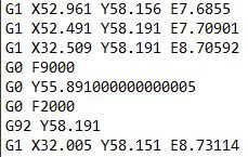
Here's a screengrab of a gcode file with a Y axis compensation move inserted. The lines starting with G1 are print moves, and the lines starting with G0/G92 are inserted by the algorithm.
![]()
You can see from the first two lines that the Y axis is moving in the +Y direction, as 58.191 (line 2) - 58.156 (line 1) = 0.035, which is a positive value. So the first value in this direction list would be +1.
Next, the algorithm ignores lines that have 0 difference between them, so line 3 is ignored (Y58.191 - Y58.191), and Line 4 - 7 is the compensation move, so the next Y move it would compare is the last line. Comparing the Y component of line 8 to line 2, we get 58.151 - 58.191 = -0.04, a negative number. Therefore the next value in our direction list would be -1. This indicates a direction change, as the two direction differ in sign.
When the algorithm compares the direction list for this portion of the file, it will see that the direction flipped at line 3, and will insert lines 4 - 7 as compensation.
The first compensation line, "G0 F9000" sets the movement speed, 9000mm/min.
The next line, "G0 Y55.89..." is the actual compensation move. You can see that it is ~2.3mm less than Y58.191, as this was the measured Y axis backlash, and that it is in the direction of the next move, -Y.
The third line resets the speed to a slower value, 2000mm/min.
And the final line, "G92 Y58.191" resets the Y axis position to the same as line 3, so the printer doesn't think it moved at all.
The backlash has now been removed, and the print can continue on. :)
Below is a video of the Y axis rack and pinion. If you watch the pinion gear you can see it jump backwards to press into the opposite side of the teeth before each direction change.
For the next update I'll be working on making sure the algorithm works for curves and other more complicated gcode moves, as well as automating the compensation process and placing the code inside of Marlin to run when a print is selected. Thanks for reading!
-
First print!
05/08/2019 at 22:59 • 0 commentsI've got a couple videos of the printer running now, including the first print!
Here's a dry print from before the extruder was working.
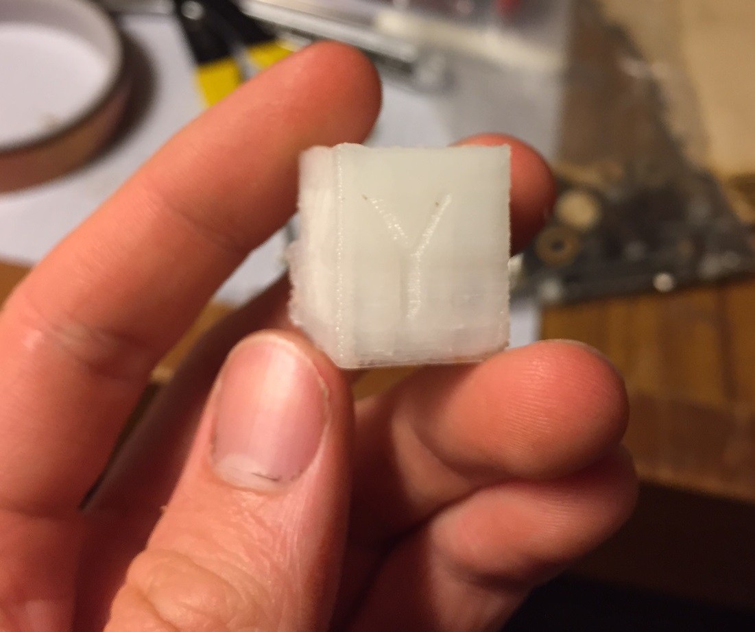
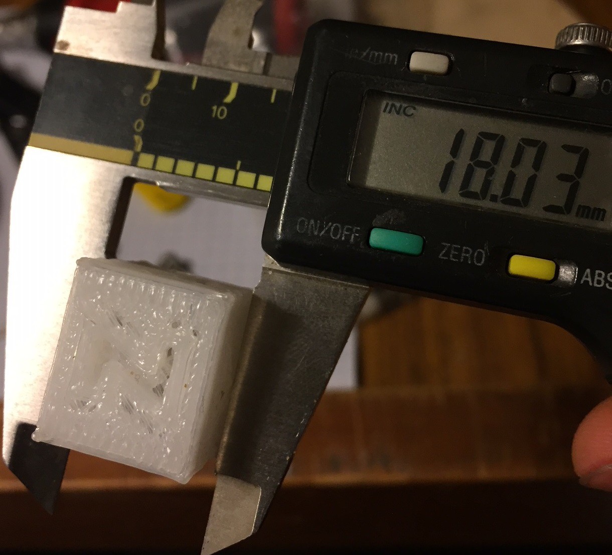
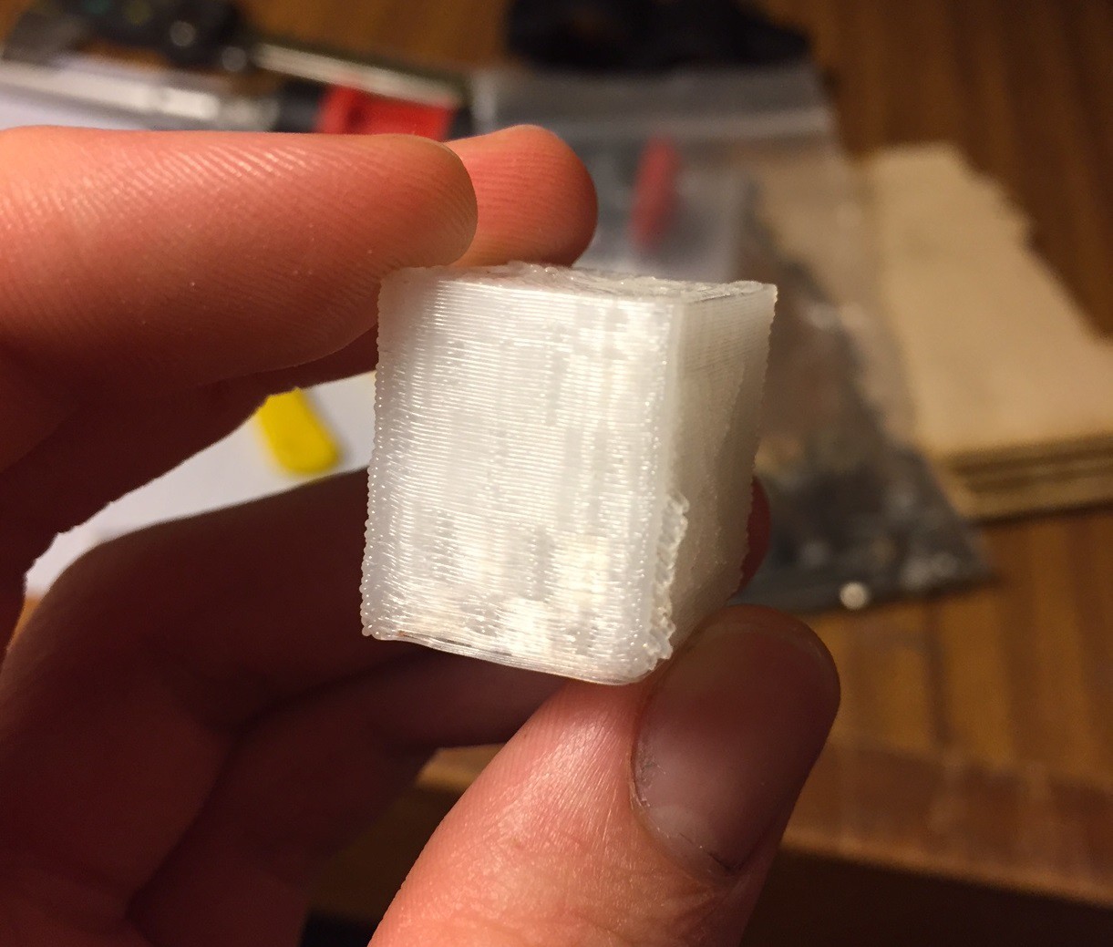
And here's the first actual print, but with a not so great extruder:And the result is, well, pretty bad!
But I think I can see what needs improvement other than just backlash.
![]()
![]()
![]()
![]()
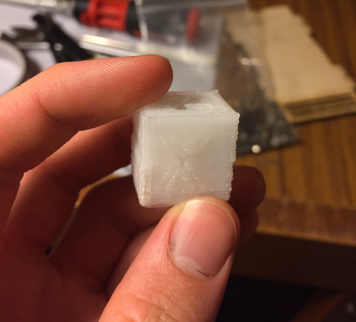
The X and Z axis are very close to the expected 20mm, (20.78mm and 20.43mm respectively) so I'll ignore any issues in those axis' for the time being. The Y axis though is almost a full 2mm smaller than it should be, so I'll focus all of my backlash compensation efforts on bringing this value closer to 20mm.
The strangest part of the cube is the checkerboard pattern on the back of the X side. This could be somehow due to backlash, but it looks like it might be the X carriage rocking back and forth. It looks like the spring mechanism keeping pressure on the roller bearings lost it's integrity, and the bearings are no longer pressing against the rails. With no proper constraint anymore, every direction change angles the carriage in an odd direction. I'm redesigning the X carriage so that the top roller bearing can be tightened against the rail with bolts and I'm hoping that will fix it.
I'll cover how I'm dealing with backlash compensation in the next update.
LP3D: A fully lasercut kit 3D printer
LP3D is an (almost) fully lasercut, low component count 3D printer with all linear motion components cut directly into the frame.