If you're interested in TDR and want to learn more about how it works, check out this great application note from Keysight. They do a great job at explaining the theory, and there isn't much I would add (well, maybe later).
The idea for this project goes back 20 years or so to a design by Tomi Engdahl. That version used 74AC logic to generate fast-edged pulses for checking relatively long cables. I'm more interested in testing smaller structures, so I wanted an even faster edge. The circuit uses a 74LVC1G14 as a relaxation oscillator. I used a 1 nF capacitor at C1, and 1.2k resistor at R6 for an oscillation frequency around 1 MHz. The output of this oscillator drives a 74LVC1G04 inverter as an output driver. R3 and R4 match the output of the inverter to 50 ohms and reduce the drive current to under the maximum 32 mA. The output is coupled to the test port and the oscilloscope input using a 50-ohm delta resistive splitter.

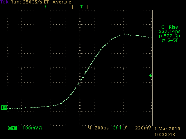
The rise time of the pulses is less than 530 ps, as shown here. To obtain this trace, the test port was capped with a 50-ohm SMA terminator.
Here's a simple example usage: the output is connected to a 50 cm section of RG316 cable, with the end unterminated.
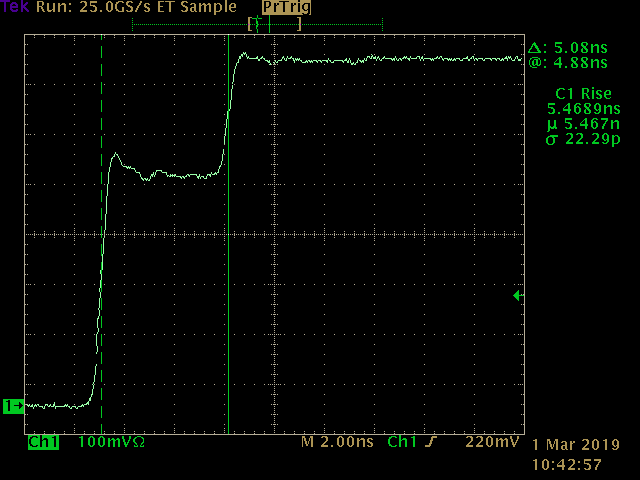
From the cursor measurement, we can determine the velocity factor of the cable. The round-trip has taken 5.08 ns, and the total distance traveled was 1 m, so the edge was traveling 1.966x10^8 m/s. This equates to a velocity factor 0f 0.656, which is around 5% off from the published value of 0.694 for this cable. Given that I didn't account for the length of the connectors, and simply eyeballed the cursor placement for the time measurement, this seems reasonable.
Going forward, I'll work out some calibration methods.
This is just the simplest example of what you can do with a basic TDR setup like this. I'll add some more examples as I use it to test some other stuff I'm building.
PCB Design
The Eagle design files for the PCB are in GitHub and also shared on OSH Park.
The parts list can (almost) be inferred from the schematic above, here it is in detail:
- (1) 1 nF 0603 capacitor
- (1) 1.2k 0603 resistor
- (1) 130-ohm 0603 resistor
- (1) 82-ohm 0603 resistor
- (3) 49.9-ohm 0603 resistors
- (1) 74LVC1G14 Schmitt-trigger inverter
- (1) 74LVC1G04 inverter
- (1) 10 uF 16V 1206 capacitor
- (2) 1 uF 16V 0603 capacitors
- (1) end-launch SMA connector for 1.6 mm PCB
- (1) PCB-mount BNC male connector (like this one)
More to Come
I'll add more information and example measurements in project logs as I go. At least now, I have a place to put it.
 Ted Yapo


 Bud Bennett
Hi Ted,
You have some really interesting projects!
Just thought you might be interested to know that there are indeed some step recovery diodes easily available (I am using some for one of my projects to generate a fast pulse).
For some reason you can't find them by using mouser's search as they have categorized these as "varactor diodes", but they are indeed step recovery diodes (look up the part number in google):
- One from Microsemi (70ps transition time - normally out of stock, but minimum order is just 1, if you are happy to wait 40 weeks): https://www2.mouser.com/ProductDetail/Microchip-Microsemi/GC2521-450A?qs=%2Fha2pyFaduh1RTLYyNedhCWxJey%252BPxV2%2FV9hBP5hCXfsQ6MxchPZeg%3D%3D
- One from Macom (150ps transition time, very cheap and a lot of stock): https://www2.mouser.com/ProductDetail/MACOM/MAVR-044769-12790T?qs=%2Fha2pyFadugtRxnexksvBiMI2gqDsaSMQhXoZmzGtjZ8My8jSvQtC%2FWlyLlZI%252Brd
I have successfully used the Macom one to sharpen a pulse to less than 200ps.
Qbort