Yann Guidon / YGDES
-
Got NTC
07/27/2019 at 23:47 • 0 commentsI finally got them !
![]()
These are negative temperature coefficient resistors, or NTC. I measured about 104 Ohms at 28°C and the resistance should drop a lot under heat. Which is going to happen because I'll put one in series with the isolation transformer, itself a mere 3 ohms. Under 220Vac, that means > 2A ! And 220V×2A=400W...
So it's going to get pretty hot.
BUT this is orders of magnitude lower than the naked transformer and the inrush current should be palatable to the 1A-rated input circuit breaker.
And as it heats, the NTC's resistance drops and the power too... It should reach some kind of equilibrium
More information is explained at https://www.tdk-electronics.tdk.com/blob/528070/download/4/pdf-inrushcurrentlimiting-an2.pdf
The exact model I have selected is B57364-s121-m, a 21mm disk that should not be touched by naked fingers, and I found the datasheet there : https://www.mouser.fr/Datasheets/_/?Keyword=EPCOS+B57364S121M&FS=True (I put the datasheet in the files section as well)
Here are the ratings :
Pmax 5W R @25°C 120Ω I max (0..-65°C) 3.5A Rmin (at Imax, 25°C) 0.4Ω That thing can absorb 1000µF loaded at 230Vac and the resistance has decreased by a factor of 300... The power loss is in the range of 1 to 2W but the part's body temperature could reach 250°C under high load !
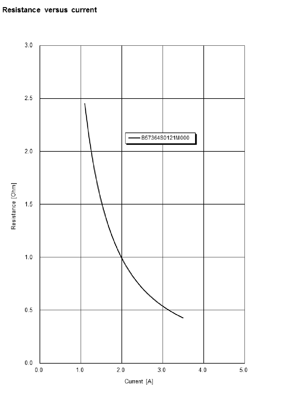
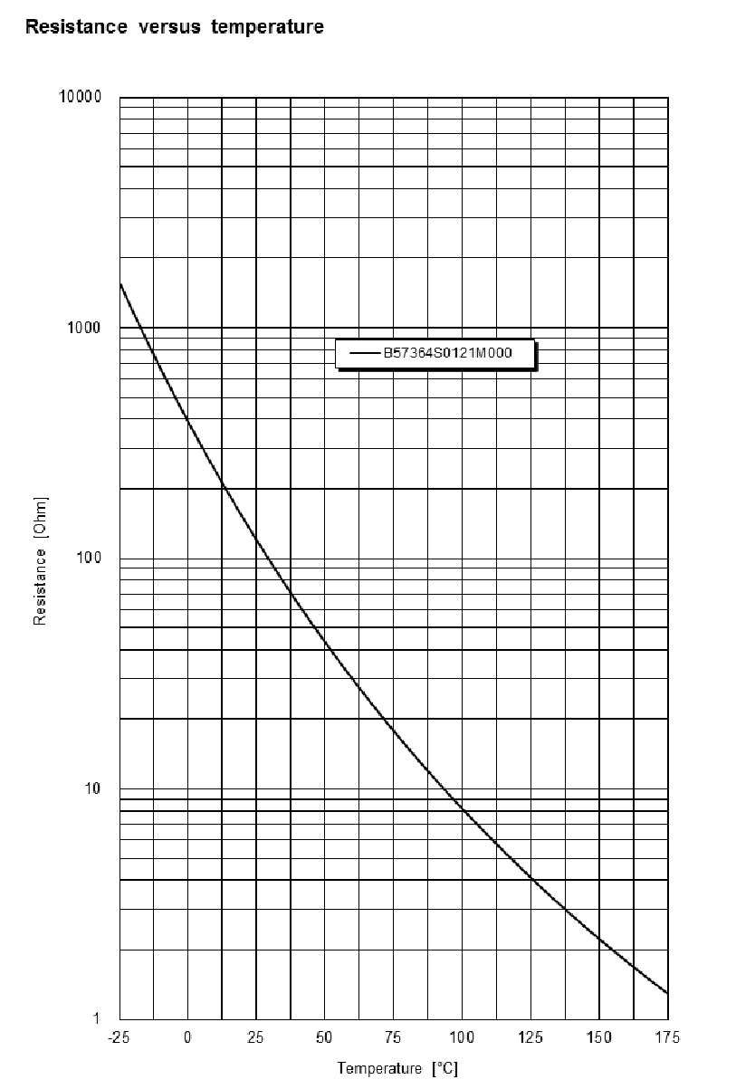
Some useful curves have been extracted from the datasheet :
![]()
![]()
Under a 1A load, the resistance is about 3 ohm, or 3W. There is enough margin to sustain some shorts and give enough time for the 1A circuit breaker to trip. The behaviour under low or light load is however not covered...
This solution is the best compromise I have found because an electromechanical delayed switch or a static relay would create too many design challenges. The small power loss is not critical in this application but convenience and repeatability matter : if the protection trips, the only thing to take care of is to not restart the circuit too early, as the NTC needs "some time" to cool enough so it won't trip again.
I'm a total noob with this specific type of part but I learned something new, YAY ! They are as cool as the "polyswitch"/"polyfuse" I have used in other systems in the past.
I did a quick test :
That thing can get quite HOT so I was wondering if a thermal switch could help and take some of the burden away...
@Morning.Star found this page: https://www.ametherm.com/blog/inrush-current/transformer-inrush-current-40va-transformerI get some interesting values:
- Stady State current : 1.8A (nothing surprising here)
- Inrush current : 54A (I expected the double: 308V/3 ohms=100A)
- Inductive impedance : 5,7 ohms
- Inductance : 0.9 H (I measured 3,3H so what happened ?)
- Energy : 1300J ? (This rating is not mentioned in the datasheet, I only see a capacity of 2.4J/K )
The NTC cools in about 100s so this is something else to consider. Maybe a light bulb would be simpler in the end ?
-
OverCurrent again again
05/20/2019 at 23:05 • 1 commentI have the relay :-)
![]()
and the socket for the DIN rail. I also added a push-button to the front panel. I can finally implement the overcurrent protection :-)
![]()
Using a 230V coil simplifies the system a lot :-)
-
A proper AC voltmeter ?
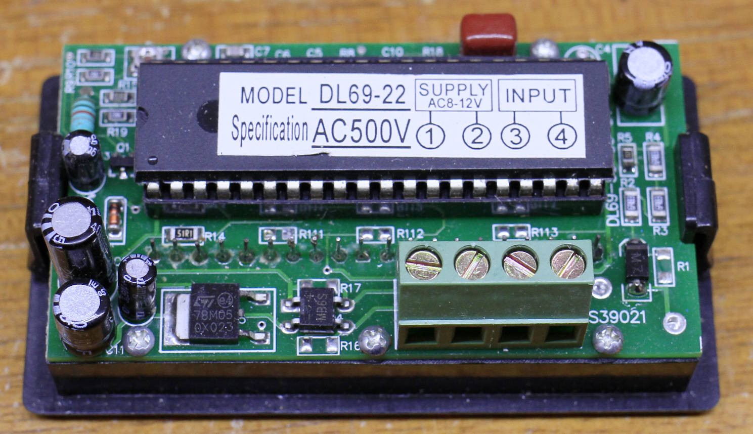
05/17/2019 at 22:34 • 0 commentsI also received a front-panel AC voltmeter.
It was a bet because the specs were not very precise but for less than 8$ on eBay, it was worth a try.
![]()
I like that this model seems to be "old school", based on the venerable ICL7107, so there is headroom for "adaptation". The box looks like it was stored 10 or 20 years (or more ?). It is rated at 500V max (peak ? RMS ?) and can work from an independent power supply though there is less than 2M Ohms of isolation. The integrated diode bridge makes the power easy to supply, with a small 9Vac transformer for example.
I just need to find the proper transformer and I'll test it, and even probably compare with my multimeters.
And of course I'll have to build a stand/support to fit the display on the fraim...
Tests with the PM5715 signal generator show that it's pretty biased ! The display changes a lot with the offset, duty cycle etc. but it shouldn't. That thing is crazy. It's obvious its power supply must float well...
Anyway the display draws 50mA @ 12Vdc, it's good to know.
-
OverCurrent again
05/17/2019 at 22:08 • 0 commentsI think I have the solution !
I have found reasonably cheap current limit detectors on eBay : https://www.ebay.fr/itm/Current-Monitoring-Relay-0-05A-16A-24V-240V-Over-Under-Current-Protection-Relay/113187089821
It costs around 30$ and I finally received it :-) The build quality is better than the much cheaper noname DIN voltmeters I received as well. The provided documentation is actually useful :-)
![]()
I have chosen the 0.05-0.5A range version so I can trip from 10W to 100W.
A very good thing is the current sense input that is separated from the other circuits. The isolation makes it perfect to sense the output current that it will break.
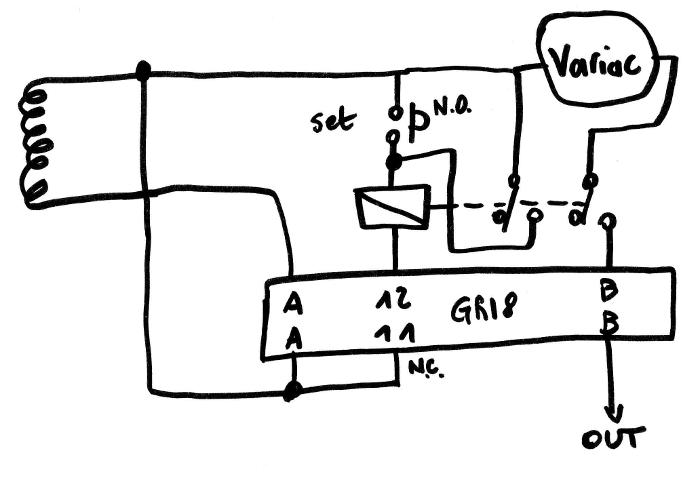
However the break is momentary only. The duration can be from 100ms to 10s but I want a bistable system to ensure that the power is totally removed until I decide otherwise. A DPDT relay can be wired as a latch, its own coil being fed by the normally-open contact. A push-button in parallel would trigger the latch (only on demand), and the GRI8-01 is wired in series on the normally-closed contact, to disengage it when the current is exceeded. Yes, a basic set/reset latch.
I don't have a DIN-railed relay but I have powerful DPDT relays with 220Vac coils so I can try something!
-
Circuit parameters
05/15/2019 at 01:25 • 0 commentsBefore powering it on for the first time, it's good to test all the parts and their connections, which is also a great opportunity to measure all the parameters :-)
- The input goes through the 2A circuit breaker. There should be no noticeable effect unless the current reaches 2A :-) So nothing to measure here.
- The output of the circuit breaker is connected to :
- a 300V MOV (a surge protection protection) : nothing to measure at low voltage
- a neon pilot lamp : shouldn't be noticeable either
- the primary coil of the isolation transformer : here we can measure the resistance and inductance:
Primary : 3 ohms, approx. 3.3 Henrys (disconnect the variac !)
Secondary : 4 ohms, approx. 3.8 Henrys (it seems to drift ???)Between primary and secondary : > 2G ohms but 1.5nF...
...
The secondary is connected to quite a few things:
- Input of the voltmeter : should not be measurable
- Capacitor and MOV : neither
- Switches: N/A :-D
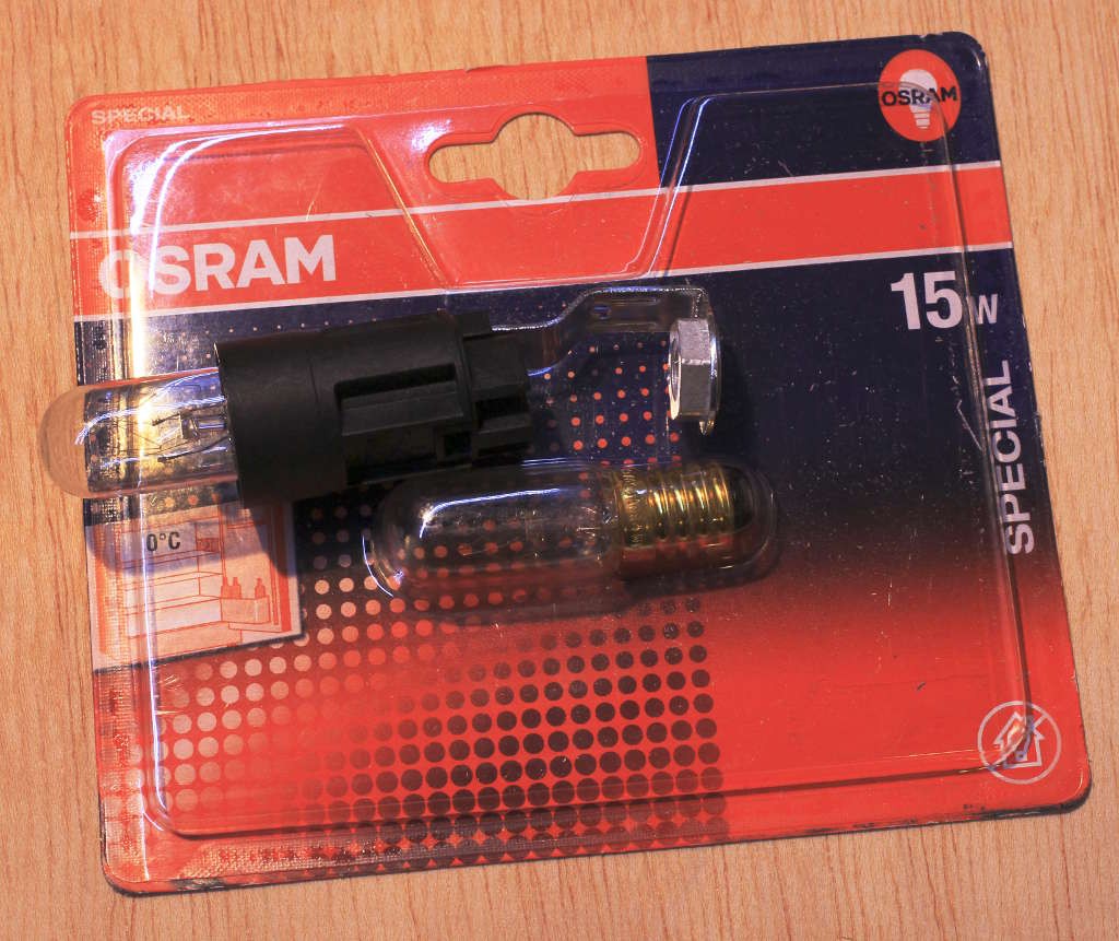
Let's see the incandescent bulbs : I measure the "cold" resistance
- 5W : 734 Ohms
- 15W : 314 Ohms
- 28W halogen : 134 Ohms
The variac is a different story, because it's variable...
-
MainsBox v1.0 ready !
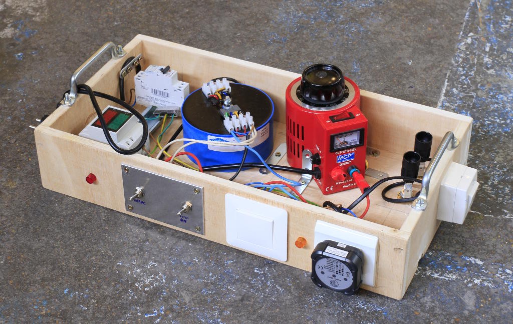
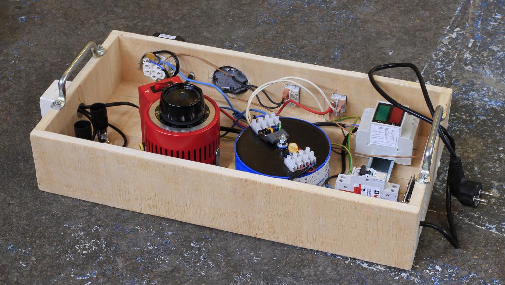
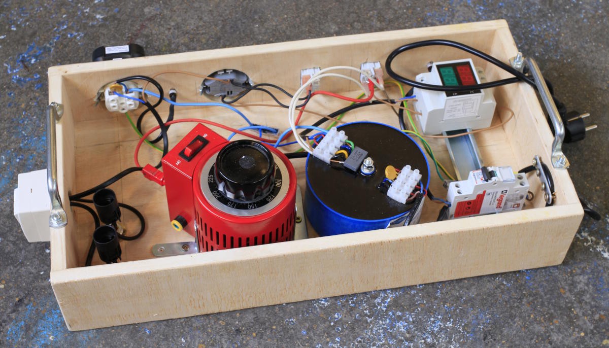
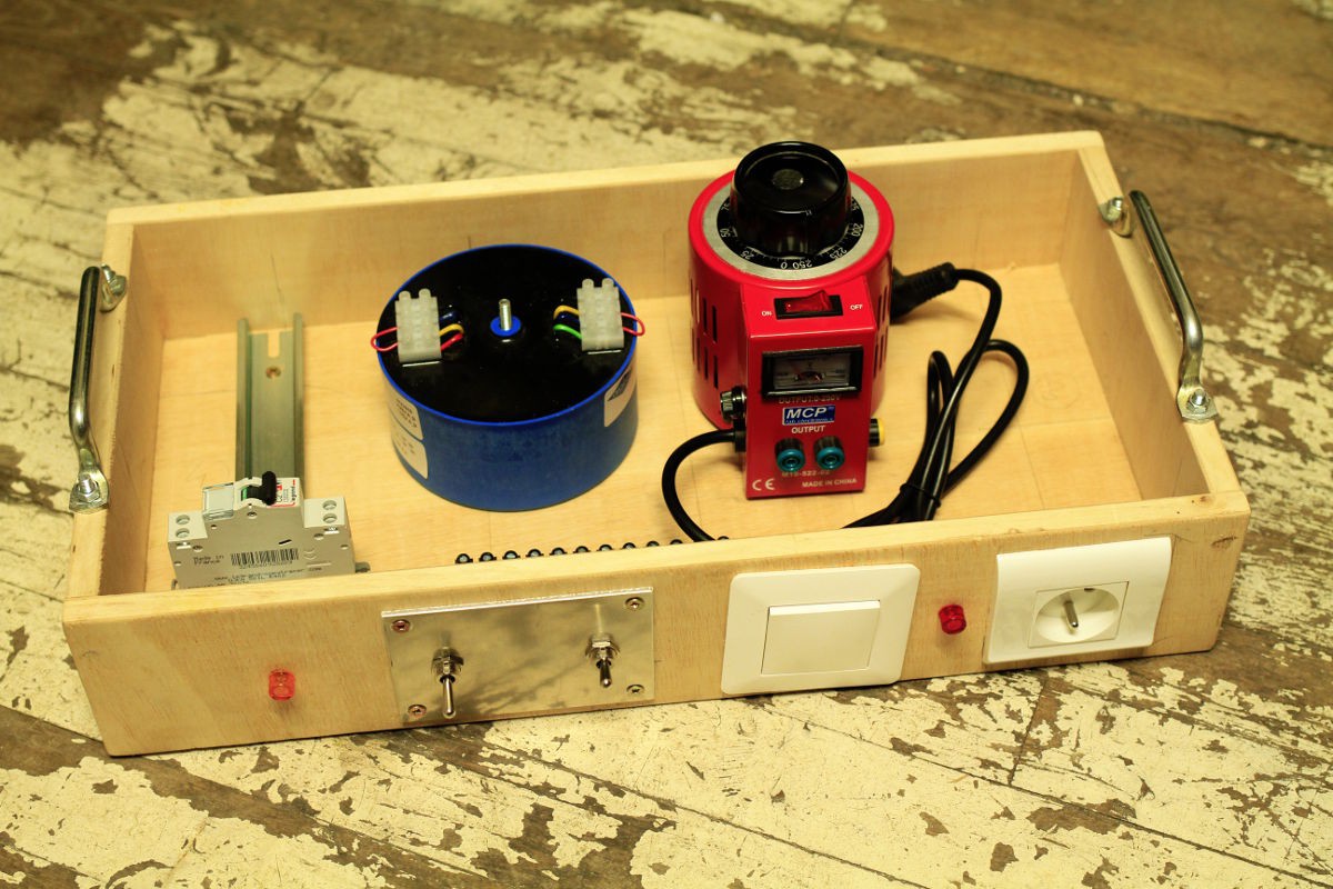
05/08/2019 at 16:16 • 0 commentsVoilà !
The first version of the box is ready for the tests, it still misses a few accessories but the system is useful and usable :-D
![]()
![]()
![]()
The main features are here, I'm waiting for the AC voltmeter to be delivered.
The passive series loads could be better but we'll see in practice if the design must be changed. After all, everything can be re-wired so there is no need to worry about "getting it right at the first try".
-
Incandescent load(s)
05/07/2019 at 15:08 • 0 commentsI'm still trying to find an active system to cut the power during over-current conditions (with selectable current values).
Meanwhile, an additional passive current limiter is easy to implement with plain incandescent light bulbs, you know, the old-school type with a tungsten filament. I measured the below bulb at about 360 ohms (cold) and it will increase during use, due to the heat, so it works almost like a "polyfuse".
![]()
The tricky part was to mount it to the wooden frame but I managed to find a decent system.
I "just need" to add more switches to bypass these loads... More switches, *sigh*...
-
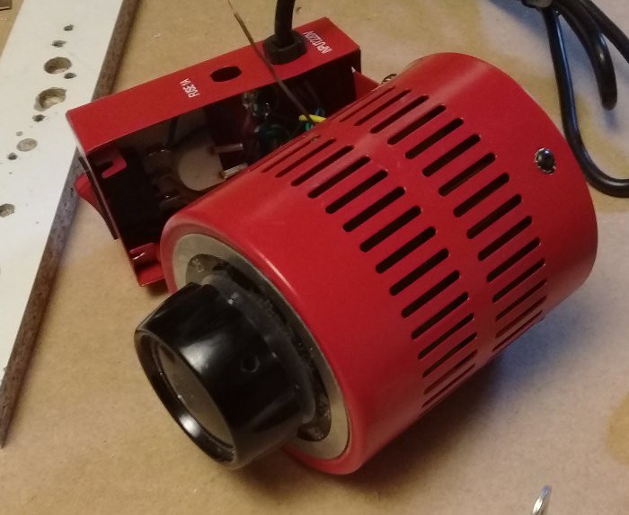
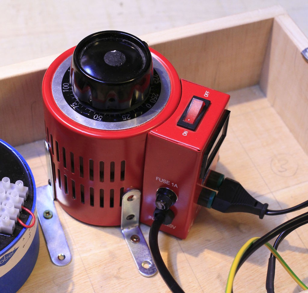
Variac: solved !
05/07/2019 at 03:26 • 0 commentsAs mentioned in the last log, the variac's issues are finally solved !
First : the fuse holder was damaged and finding an exact replacement part was almost impossible.
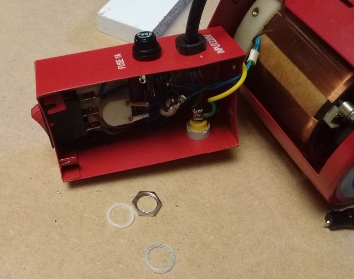
![]()
I found a suitable fuse holder but the hole was not adapted...
Enter Alex and his extensive collection of power tools and bits.
![]()
A conical bit was used to reshape the fuse holder's hole so the new part would fit :-)
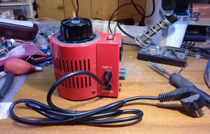
![]()
After a bit of re-soldering, the variac is finally operational !
![]()
But wait, it's not finished.
Tying the variac to the wooden box is another challenge. The variac has no fixation point so it would move around in the box... which is out of question.
Alex has found a very smart, cheap, efficient and unintrusive system with L-shaped steel bits, which by coincidence have the right dimension for the holes. 4 of these are now keeping the variac in place !![]()
The trick was simply to unscrew the frame's screws...
Some screws tie the assembly to the wooden frame, and that's it.
To say I'm thankful for Alex's help is an understatement ;-) -
First assembly
05/02/2019 at 21:43 • 0 commentsMore woodwork and metal work later, the "rack" is looking more like something that could work !
![]()
Elements are still missing but some devices are on their way :-) I'll be able to install a combined voltmeter/ammeter soon.
The big question is how to attach the variac to the frame but Alex might have found a great solution.
And the other big great news : the variac suffered from bad packaging and the fuse holder broke during delivery but now (after 2 long years) it is repaired ! In part thanks to Alex again :-)
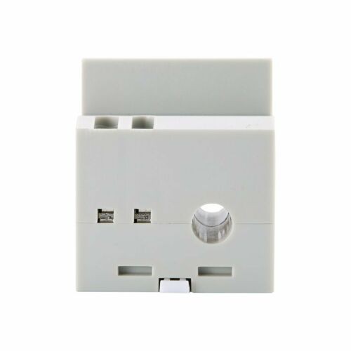
BTW, I'll soon mount a DIN-rail module to display current and voltage. The current sense is inside the module and one wire goes through it :![]()
This simplifies my system because I can power it from the secondary of the isolation transformer while sensing the current that goes to the wall plug. What I still need is an AC voltmeter to measure the output of the variac.
-
More woodwork
04/30/2019 at 01:39 • 0 commentsToday I took some time to progress with the wooden frame : two big sturdy handles, a fixing point for the isolation transformer, and large holes for the front switch and "wall plug".
The great thing with this style of circuit is the possibility to wire something that is functional despite the absence of other parts. I can re-wire later :-)