 Jack Flynn
Design Style
My vision for this design is to have the final boards produced with a black PCB and to remove the silk screen from the top overlay. I think this should give the cube a really modern and clean look while really allowing the LEDs to shine.
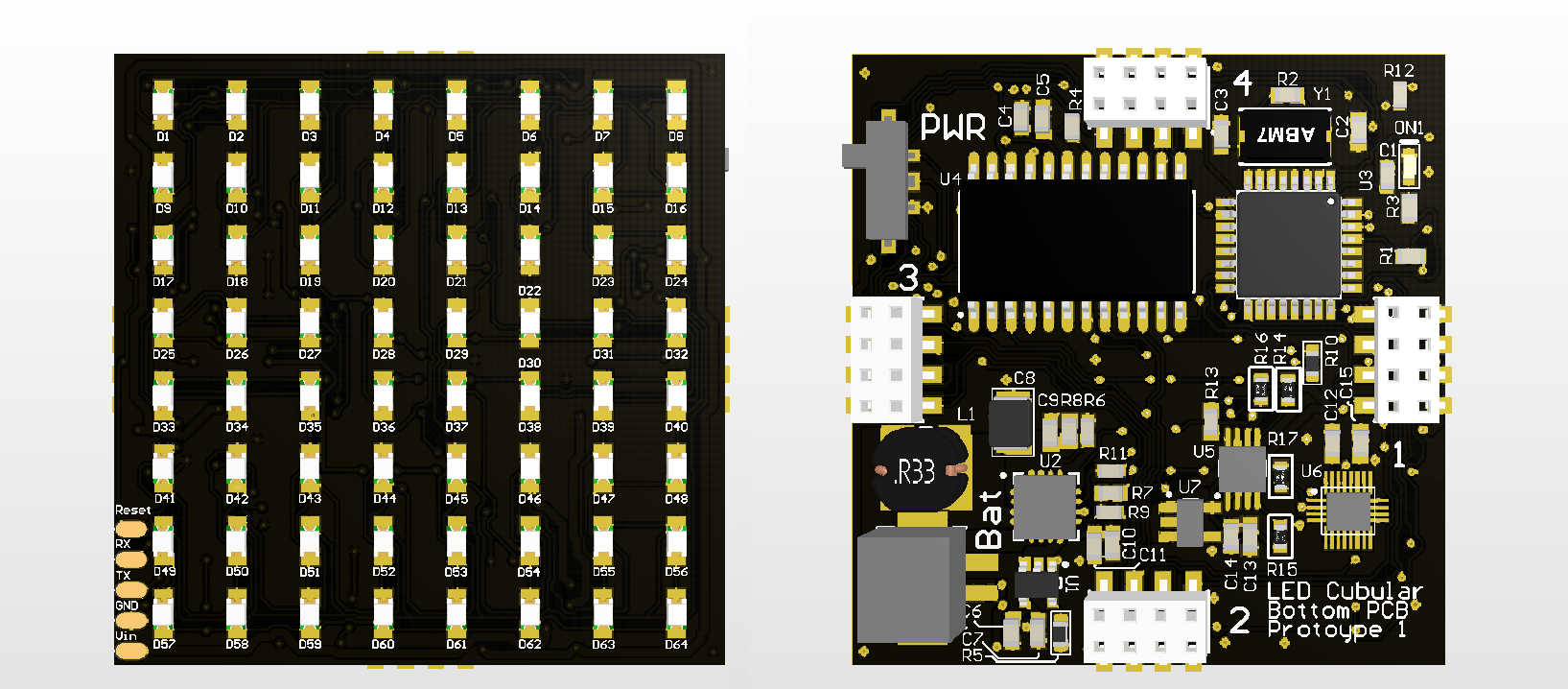
My latest changes to the bottom PCB are purely for visual. I've tried to add clear text where possible to highlight the key input/outputs and for prototyping I've left the Top Overlay on so we can see the individual LED numbers and interface pads.
General Connections
I've produced the following diagram in an effort to explain the general connection layout and functionality.
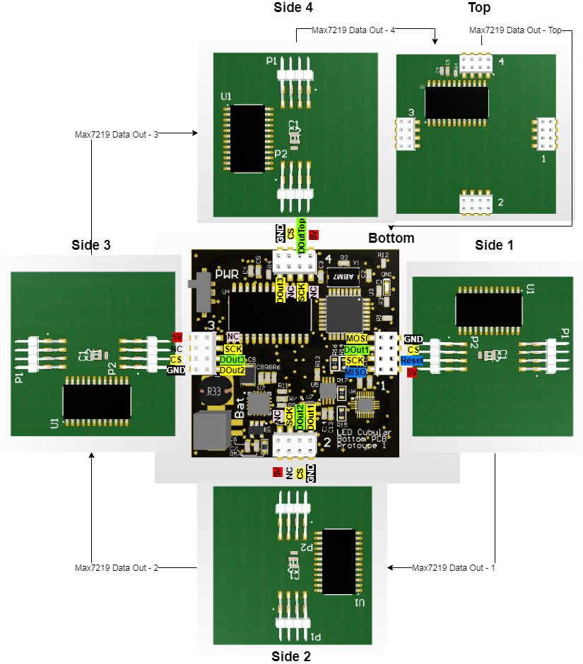
Each side panel and top panel have a max7219 for running the LEDs. These are daisy-chained through the bottom board as the data out of each max7219 is passed to the next board. Port 1 on the bottom panel can be used with an ICSP in order to burn the Arduino Bootloader to the ATMega328P as well as being used to drive the first side panel.
Discussions
Become a Hackaday.io Member
Create an account to leave a comment. Already have an account? Log In.
There are too many designs are accessible right now, can see all photos which the writer share on this essay writing service blog. These General designs pictures are significant for those individuals who are keen on this work.
Are you sure? yes | no