 Jack Flynn
I put together a short video of my pcb track layout for the 64 front LEDs on the side panel. I'm no video editor but I think it comes across well. As can be seen from the schematic, the LEDs are connected to the Max7219 in a matrix layout.
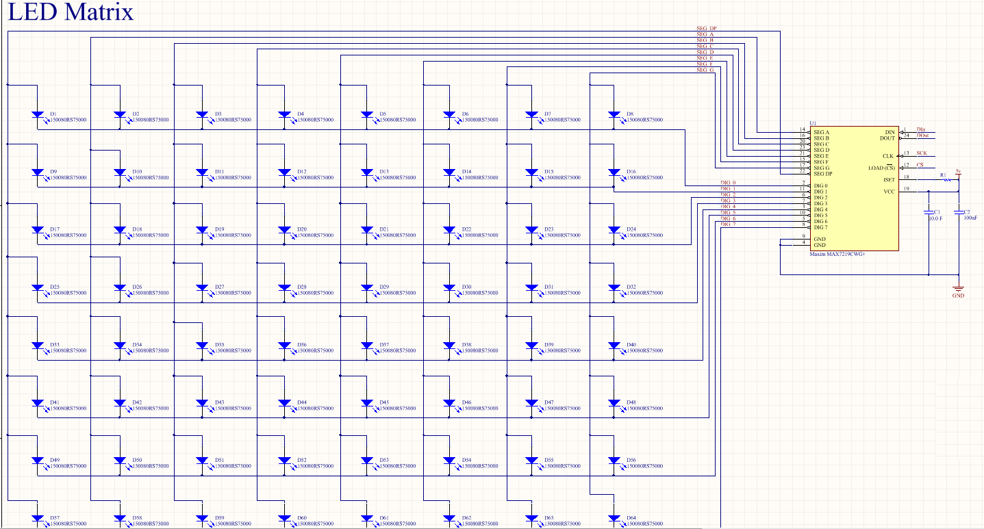
This daisy chains the LEDs together in columns and rows which initially makes it difficult on a 2 layer design to not end up getting your wires crossed and losing a tonne of space on the bottom layer. I came up with a way of interconnecting the columns and rows (8x8) by passing the 6 mil traces under the LEDs. I could fit 2 lines under each LED while maintaining a 6mil clearance. Something I note that the Bantam Tools CNC mill should be able to achieve. Check out the video to see how I pulled it off;
Discussions
Become a Hackaday.io Member
Create an account to leave a comment. Already have an account? Log In.