 Alastair Hewitt
The first 5 chips of the GPU were added this weekend. This included the H register (4-bit counters and buffer) and the V and S registers (8-bit flip-flops). Most of the time was taken up with software development for a video timing loop.
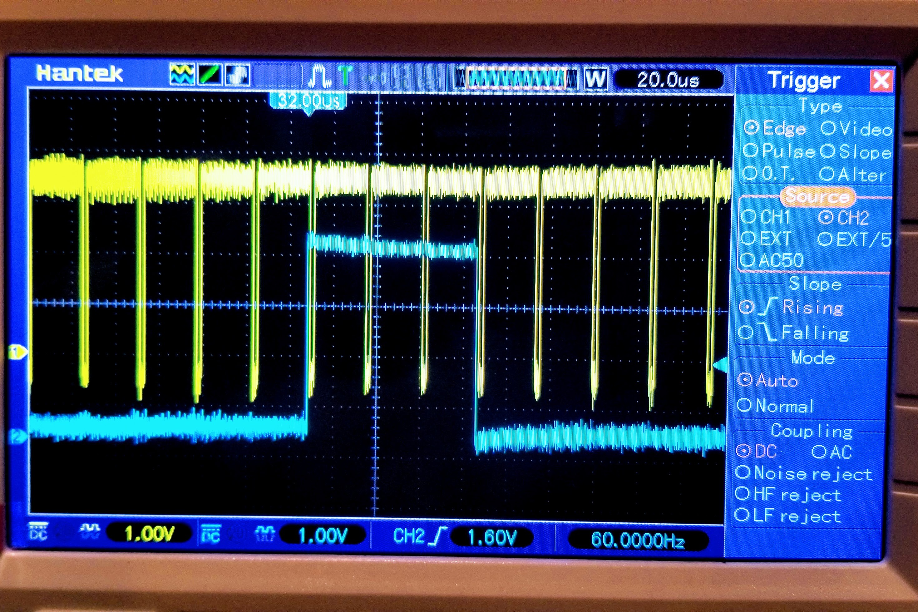
The end result was the 38.4 kHz H-sync and 60 Hz V-sync signals. This matches the modified SVGA timing used with the Arduino in earlier testing. The syncs follow the GTF timing spec with a negative H-sync and a positive V-sync signal spanning three H-sync pulses (as seen below).
The actual firmware is highly optimized and uses a custom ALU function to return all the video timing based on a single counter and video-specific modulo function. There is still a lot missing from the ALU with only the basic binary functions like ADD, SUB, AND, and OR available, so a multilayer loop was coded to calculate the timing in real time.
A precise cycle count of 208 is required for each iteration of the video loop regardless of any conditional branching that occurs. This is achieved by adjusting the length of the inner loop (shown first in the listing below). This tight 5-cycle loop is used to burn up the remaining cycles given an initial value loaded into the HL register. The other execution paths are padded with NOPs to be divisible by 5 cycles.
The video timing loop uses four bytes of the zero page:
- 0x1FF20: $BURN - temporary store of burn-down count.
- 0x1FF21: $SCAN - line of text glyph to render (0-7)
- 0x1FF22: $LINE - line of video memory to read (0-79)
- 0x1FF23: $SYNC - mask of the V-blank and V-sync bits combined with the scan to make up S register.
The code is located at the reset vector (0x08000) and consists of 109 bytes. The first condition will increment the scan count when the burn loop expires. The V-sync bit is cleared when the scan count is greater than 3. The second condition is met when the count gets to 8 and results in a reset to the scan count and an increment of the line count. The third condition is met when the line count is greater than 75 and results in setting the V-blank and the V-sync bits, where the latter is only set for the first cycle. The final condition is reached when the line count reaches 80 and both the line count and mask are reset to zero.
The listing is show below where the numbers in square brackets represent the number of cycles. The address and encoding is shown along side the nemonic and a comment per instruction.
[2] 8000: 9420    LD Y, 20
[4] 8002: 0804    MVHLZ ND1       # immediate load of $BURN
[2] 8004: 9510    LD HL, 10
[3] 8006: 582C    SUBH D1Z, ND1   # count down to -1
[2] 8008: A606    LDP PC, 06      # 5-cycle loop, [5n - 1] cycles

[2] 800A: 9421    LD Y, 21
[3] 800C: 591F    ADDH D1Z, HLD1  # increment $SCAN
[2] 800E: 9423    LD Y, 23
[4] 8010: 1E5E    ORHL D1Z, SA    # strobe scan with $MASK
[2] 8012: 9421    LD Y, 21
[2] 8014: 9520    LD HL, 20
[3] 8016: 5C2C    SUBH D1Z, NA    # compare using $SCAN - 2
[2] 8018: 9423    LD Y, 23
[.] 801A: A5DF    LDP HL, DF      # clear vsync
[3] 801C: B5FF    LDN HL, FF      # leave vsync
[4] 801E: 184C    ANDHL D1Z, ND1  # update $SCAN if S > 3
[2] 8020: 9421    LD Y, 21
[2] 8022: 9570    LD HL, 70
[3] 8024: 5C2C    SUBH D1Z, NA    # compare using $SCAN - 7
[2] 8026: 951F    LD HL, 1F       # set burn count to 32 (31 + 1)
[2] 8028: 8080    NOP; NOP
[2] 802A: 80      NOP
[2] 802B: B600    LDN PC, 00      # return [49]

[2] 802D: 95FF    LD HL, FF
[4] 802F: 0804    MVHLZ ND1       # immediate load of -1
[2] 8031: 9422    LD Y, 22
[2] 8033: 9510    LD HL, 10
[3] 8035: 5B1E    ADDH D1Z, VD1   # increment $LINE
[2] 8037: 954B    LD HL, 4B
[4] 8039: 1D2E    SUBHL D1Z, EA   # compare using $LINE - 75
[2] 803B: 951A    LD HL, 1A       # set burn count to 27 (26 + 1)
[2] 803D: 8080    NOP; NOP
[1] 803F: 80      NOP
[2] 8040: B600    LDN PC, 00      # return [48+26]

[2] 8042: 954C    LD HL, 4C
[4] 8044: 1C2C    SUBHL D1Z, NA   # compare using $SCAN - 76
[2] 8046: 9423    LD Y, 23
[.] 8048: A510    LDP HL, 10      # vsync off
[3] 804A: B530    LDN HL, 30      # vsync on
[4] 804C: 0804    MVHLZ ND1       # immediate load of $MASK
[2] 804E: 9422    LD Y, 22
[2] 8050: 954F    LD HL, 4F       # set HL to 79
[4] 8052: 1C2C    SUBHL D1Z, EA   # compare using $LINE - 79, strobe  E
[2] 8054: 9514    LD HL, 14       # set burn count to 21 (20 + 1)
[2] 8056: 8080    NOP; NOP
[2] 8058: 8080    NOP; NOP
[2] 805A: B600    LDN PC, 00      # return [48+25+31]

[2] 805C: 95FF    LD HL, FF
[4] 805E: 0806    MVHLZ XD1       # immediate load of -1, strobe X
[2] 8060: 9423    LD Y, 23
[2] 8062: 9500    LD HL, 00
[4] 8064: 0804    MVHLZ ND1       # immediate load of 0
[2] 8066: 9510    LD HL, 10       # set burn count to 17 (16 + 1)
[2] 8068: 8080    NOP; NOP
[1] 806A: 80      NOP
[2] 806B: 9600    LD PC, 00       # return [48+25+30+21]
Discussions
Become a Hackaday.io Member
Create an account to leave a comment. Already have an account? Log In.