-
Where Next?
03/27/2019 at 21:57 • 0 commentsThis project was featured on hackaday.com yesterday. This surprised me as it's at such an early stage, but thanks anyway [Brian Benchoff]!
Seeing as this has brought some more attention to the project I thought it would be a good time to explain where I want to take this next. I'm fairly happy with the prototype that I've built and I don't think that there are any serious flaws that need to be addressed. There are some minor tweaks though:
- Change the colours for the alternative functions on the keyboard labels. Some characters like the full stop and comma are hard to distinguish and I think darker colours would improve the contrast and help here. I'm also going to try printing the labels on glossy photo paper to see if that helps.
- The bars that hold the keyboard labels in place need to be slightly thicker for a more secure fit. A very minor change.
- Change the software so that it uses the more generic terms "modifier 1" and "modifier 2" instead of "shift" and "symbol".
Those things are just tweaks though and don't really add anything new to the design, so here are the REAL improvements that I plan to make:
- Add a version of the software that works with an IO expander chip so that the keyboard can be used with devices that aren't so well endowed with GPIOs, such as ESP8266 and Raspberry PI. This is actually written and will probably be the subject of the next log.
- A proper event queue callback and functions to poll the keyboard state.
- Allow for character sets other than 7 bit ASCII.
- Turn the software into a library.
- Fully parametrise the key label spreadsheet, include cutting instructions on the sheet itself with a guide to check that it has been printed at the correct size and print each label strip multiple times to make best use of the paper and allow for cutting mistakes.
- Fully parametrise the OpenSCAD code for the bezel, and include options to properly secure the bezel to the circuit board, including a full wrap around case.
- Write proper assembly instructions.
And a few things that are more long term:
- Allow for offset rows on the bezel, so the rows are slightly staggered like you get on most keyboards.
- Add support to allow modifiers to be toggled on or off with a press instead of needing to be held. This would be useful for single handed operation.
- Add support for external control of modifiers through, for example, a three position switch. This could allow for more more than two modifiers.
- Build some sort of central configurator, where you entry your keyboard layout once and it produces all the design files and source code.
I think that should be enough for now.
-
Keyboard Assembly 3 - 3D Printed Cover
03/26/2019 at 20:34 • 0 commentsThis is the last of these logs covering my first prototype and I'll be talking about the 3D printed front cover.
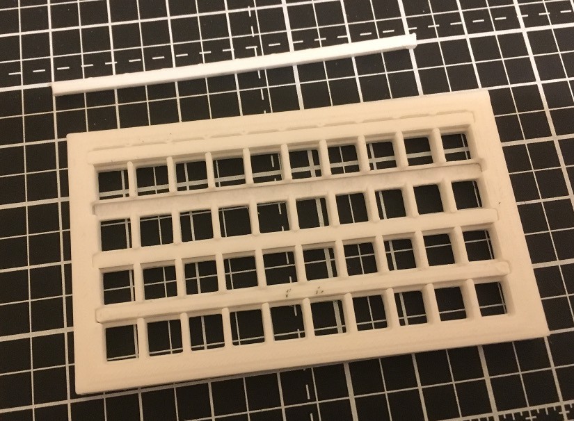
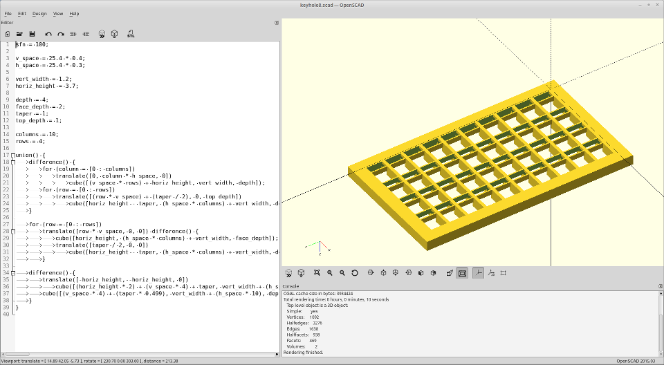
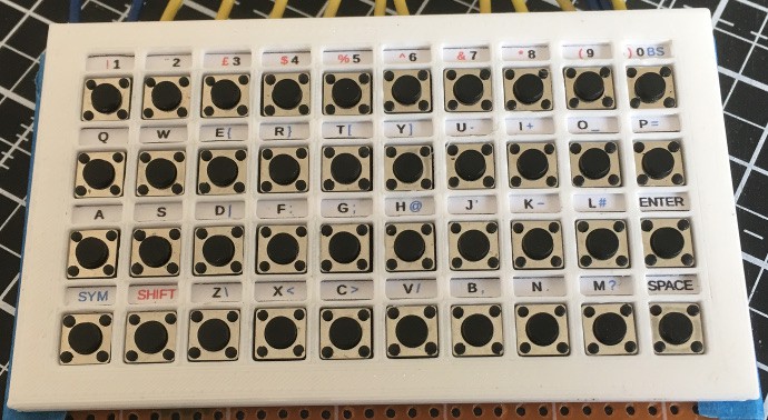
The most important function of the front cover is to hold the key labels, which are paper strips that go above each row of keys (see previous log). There are four rows of holes to accommodate the switches and above each row is another row of smaller holes to accommodate the labels. The label is slotted in from the back of the cover and a plastic bar (also 3D printed) holds it in place. Here is a picture of the back to help make things clearer. I've removed one of the bars that hold the labels in.
The parts were designed on OpenSCAD, which, for those of you that don't know it, is a tool that allows 3D models to be defined programmatically. The output is an STL file which can then be sliced and printed or incorporated into a larger part such as a complete case.
![]()
One of my aims with this project is to make the keyboard layout fully parametric. The current design allows the number of rows and columns to be changed but I would like to add more flexibility in future, such as allowing offset key rows or taller row labels.
The OpenSCAD files can be downloaded here. PLEASE NOTE: I have reorganised the downloads so that everything is in one archive. This one also contains the software and the key label spreadsheet covered in the previous logs.
-
Keyboard Assembly 2 - Key Labels
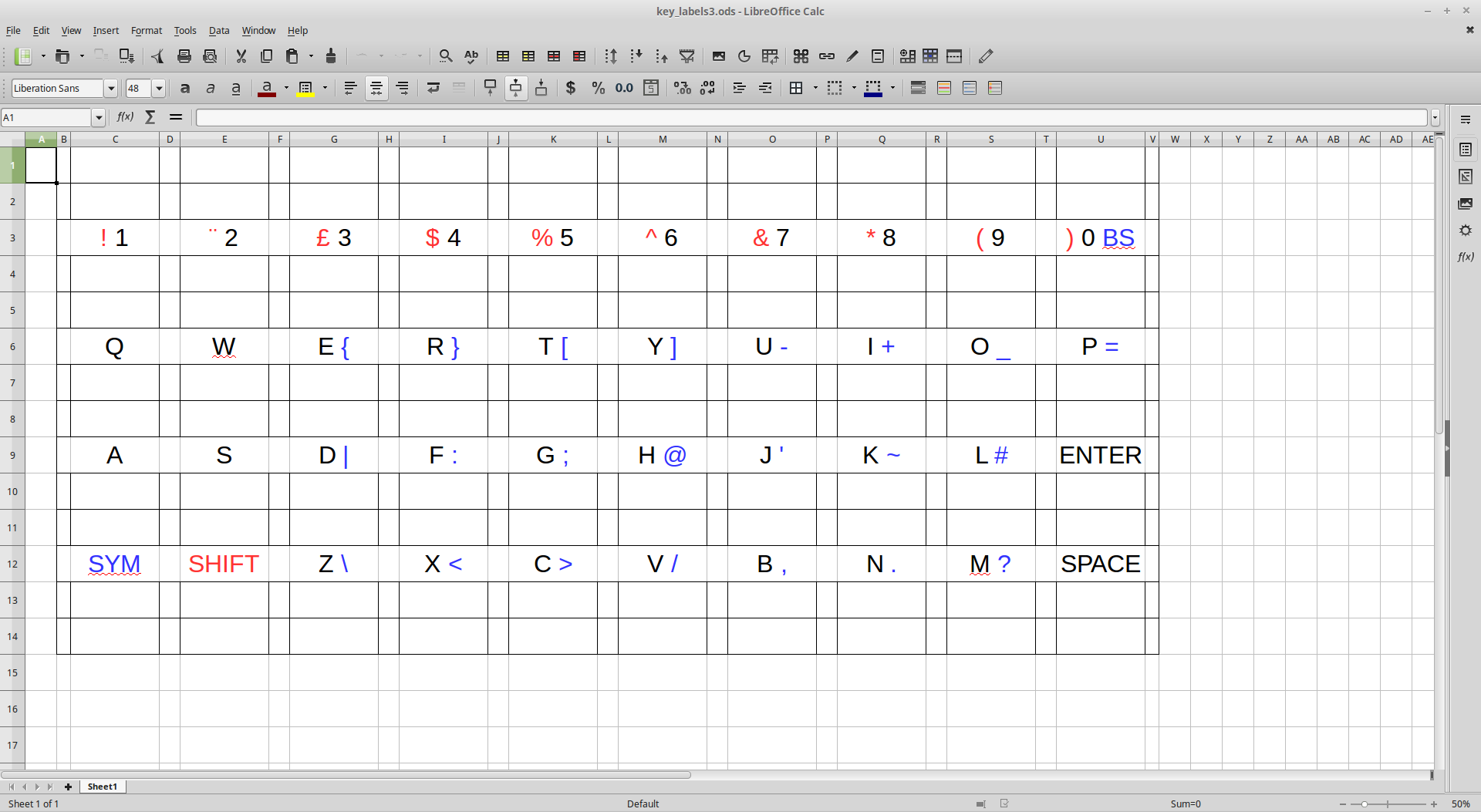
03/21/2019 at 22:14 • 0 commentsUnless you have a very good memory, it's useful for the keys on a keyboard to be labelled in some way. The usual way that this is done on a professionally produced keyboard is by printing or laser etching on to the keycap, but these methods are out of my reach and in any case, I'm not using keycaps, just the bare switches. What I have done is put the key marking just above the relevant key and this means that I can print a strip of markings for each row on a normal inkjet or laser printer.
I needed a good way to lay out these strips, so I tried a number of different graphics packages to see what worked best. I eventually found that the best graphic package for this was a spreadsheet.
Yes, that most abused piece of office productivity software is now a keyboard labelling tool in addition to being a database, project planner, form designer and all the other things that it gets used for.
![]()
Above is the spreadsheet in LibreOffice Calc. Each key is represented by a single cell and I'm using different colours to indicate the normal and modified key functions. The B and V columns are small overhangs to allow the strip to be positioned correctly in the 3D printed part. If you don't have access to a 3D printer, you could print these on to label paper and stick them directly on to the perfboard.
To get enough accuracy, I had to specify the cell sizes to be ten times their actual size and change the print setting to print at 10% size. When printed correctly, the strip should be 77mm long.
The spreadsheet is available for download. I also plan to do a more flexible version at some point where you enter the number of rows and columns and the marking for each key on one sheet and then run a macro which produces a second sheet which you print.
-
Keyboard Assembly 1 - Electrical
03/18/2019 at 22:52 • 0 commentsI'm going to go over how I assembled the prototype starting with how everything is connected up on the perfboard. I've already covered some of this in the first "Keyboard Basics" log, so this is mainly a recap with some more details.
The perfboard is the standard single sided type with holes spaced at 2.54mm/0.1in. Each switch takes up three holes across and four down and the grid is 10x4, so this gives us 30x16 holes. However, I also want a two holes margin around the whole board which I'll eventually use to help hold the board in a case, so the total size is 34x20 holes.
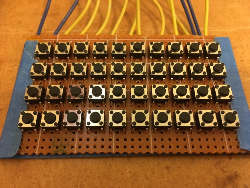
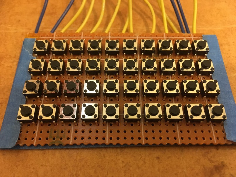
The switches are also a common type sold as "6x6x4.5mm Panel PCB Momentary Tactile Push Button Switch 4 Pin DIP". These fit into the perfboard with the pins facing top and bottom as close as they will go leaving a two hole gap around each edge. It should look something like this. Ignore the blue tape and wires for now:
Then I flipped the board over and folded the left side (as we are looking at the back of the board) pins of each switch outward and the right side ones inward. I made sure that each switch is flush with the board when folding the pins. I used the 3D printed part (which I know I've not covered yet) to check the switches were correctly positioned.
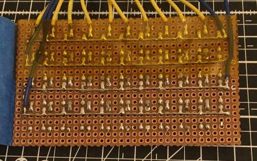
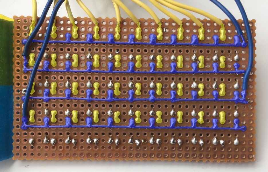
Finally, I soldered the switches as per the picture below. An uninsulated copper wire carries each row connection across the board and the column connections are carried through the switches (as explained in the log I mentioned earlier). In the picture below, I've coloured the row connections blue and the columns ones yellow to make things easier to follow. The uncoloured pins are not connected to anything and are just holding the switch in place. The row and column connections have to be bridged over two pads, which is why the soldering is messy. Well, that and the fact that my soldering is messy anyway.
![]()
The final bit of soldering is attaching the wires for the rows and columns. I put two row wires at each side to avoid a clump of wires at one end. If you look at the top left corner of the picture above you'll see two pieces of tape. I put a piece of kapton across the board to keep the wires in place and then later added a piece of masking tape (painters' tape) over the whole back side of the board when I found out that my fingers would short out the connections when I was holding it. If I had realised that in advance I could have skipped the kapton and just used the masking tape.
Now we have a keyboard and the code to scan it, but we need to know which key is which, so next time I'll cover making the key labels. -
Keyboard Scanning Demo Code
03/16/2019 at 14:41 • 3 commentsAs promised, I've put the keyboard scanning code covered in the last three logs online and you can download it from this page: https://dboucher.org.uk/keyboard.
![]()
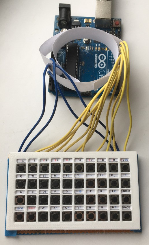
Keyboard with Arduino UNO and paper pin insulator.
This version is set up for Arduino but it should work on anything Arduino compatible with enough GPIO pins. I've used it on a Teensy LC for example.
There is a README with more info in the download. I hope you find it useful.
-
Keyboard Basics - Key Mapping
03/14/2019 at 20:50 • 0 commentsLast one of these I promise.
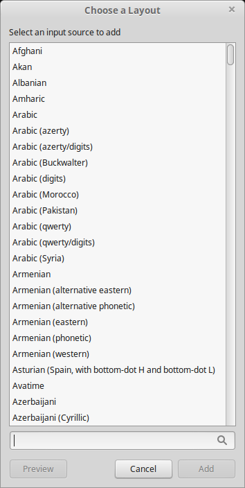
One of the problems with producing any sort of keyboard is all of the different layouts. Layouts vary by country, language, country AND language and sometimes there are different layouts for the same country and language.![]() A list of keyboard layouts in Linux Mint (just the 'A's).
A list of keyboard layouts in Linux Mint (just the 'A's).
One of the main aims of my project is to produce a design that the average electronic hobbyist can build and then customise the layout to their own requirements. Don't like my layout? No problem, you can change it.
There are two forms in which the keyboard layout is represented, the physical markings on the keyboard itself and in software. We'll cover the first of these another time, but I'll finish off this trilogy of logs about keyboard basics by discussing key mapping in software.
So far, we can scan the keyboard and get a series of key press, repeat and release events, but the key itself is only identified by a number. What we need to know is what the key is for. Most keys will represent a printable character of some sort but a few will have other functions.
For my key map, I use a two element structure to represent each key, The first element specifies whether the key is a normal printable key or it it has another "special" function. The second element is either the character to be printed for a normal key, or a value from a #define that indicates which "special" key it is.
To give you an example, my prototype has ten columns and four rows of keys, giving forty in total. If I press the key in the first column of the second row, the scan routine will read the 11th key map entry and find that this is a normal printable key and that it is a "q".
But what if I want an uppercase "Q" instead? I need a shift key for this, which brings us on to modifiers. Modifier keys, when held down, change the function of other keys, which means changing the key map used. I decided to have two modifiers, as I have limited space on the keyboard to print the alternate functions for each key. I also decided not to allow modifiers to be used together, as the keyboard can only reliably detect two simultaneous key presses (see the first keyboard basics log for an explanation).
This gives each key three possible functions, one on its own and one with each modifier, and so three key maps are required. The mapping routine first checks which modifiers are pressed to determine which map to use, then maps the key as explained above. Ta Da! Now we can type "Hello World!" complete with uppercase characters and punctuation.
And so ends this (longer than originally planned) explanation of how to scan a keyboard. I will post the code for this once I have tidied it up a bit and I will also be moving on to the hardware side of things. -
Keyboard Basics - Debouncing and Repeating
03/12/2019 at 22:27 • 1 commentThis is the middle bit of the keyboard reading code. At this point we have a map of which keys are pressed and we need to start turning that into key events. The events that we need are:
- A key has been pressed,
- A key has been released,
- A key is repeating.
In order to determine whether a key has been pressed or released we need to keep a record of the state of the keyboard on the last scan and check for state changes. This is simple enough, but the repeat event requires a little more work. For key repeat, we need to know how long a key has been held down, so we need to do a little bit of timing. There are actually two time periods associated with key repeat: the first is how long a key must be held down to produce the first repeat event and the second is how much additional time it must be held down for each additional repeat event. The first of these intervals is generally longer than the second.
The way that I've handled this is to have the scan routine run at regular intervals. I could do this on a timer interrupt but for simplicity I'm just using the millis() function to control a delay between scans. Then I maintain a counter of how many scans a key has been held down for.
I can also use this for key debouncing. Bouncing is when a circuit is made and broken multiple times as a switch is being pressed or released, which in a keyboard would cause spurious key press and release events. I've not actually had a problem with this unless I scan the keyboard continuously with no delay between scans, but I've included code to deal with it anyway just in case.
Putting all these things together, this is how I'm handling this part of the process. Firstly, though, I need a few constants:
- KEY_SCAN_INTERVAL = number of milliseconds between keyboard scans.
- KEY_DEBOUNCE = number of scans before a key press event is generated.
- KEY_FIRST_REPEAT = number of scans before the first repeat event is generated.
- KEY_NEXT_REPEAT = number of scans between subsequent repeat events.
Then the code does the following:
- Scan the keyboard every KEY_SCAN_INTERVAL milliseconds.
- For every scan that a key is held down, increase its scan counter by 1.
- When a key has been held down for KEY_DEBOUNCE scans, generate a key press event for it.
- When a key has been held down for KEY_DEBOUNCE + KEY_FIRST_REPEAT scans, generate a key repeat event.
- When a key has been held down for KEY_DEBOUNCE + KEY_FIRST_REPEAT + KEY_NEXT_REPEAT scans, generate a key repeat event and set the scan count back to KEY_DEBOUNCE + KEY_FIRST_REPEAT.
- When a key is released, if the scan count is KEY_DEBOUNCE or more, generate a key release event. Set the scan count back to 0 whether or not a key release event was generated.
Now we have a stream of key events but we only have the key numbers when what we really need to know is what that key represents. That needs key mapping which will be the subject of the next log.
-
Keyboard Basics - Scanning and Phantoms
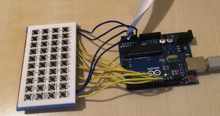
03/09/2019 at 10:40 • 0 commentsIn the last log I covered how a keyboard is wired up. This time I'll cover how it is scanned. My prototype thumb keyboard has four rows of ten keys each, giving a requirement for 14 GPIOs in total. This puts it within the capabilities of an Arduino. There won't be many pins left for anything else, but I'll cover a way around that in a later log.
Prototype 1 connected to an Arduino UNO. The piece of paper is just there to stop two of the pins shorting out.
To scan the keyboard, all the GPIOs are first set to INPUT_PULLUP, then each row GPIO in turn is set to output and pulled LOW and each column GPIO is read. A column GPIO that is LOW indicates a pressed key. The row is then set pack to INPUT_PULLUP and the next row is scanned. The end result of this is a map of pressed keys.
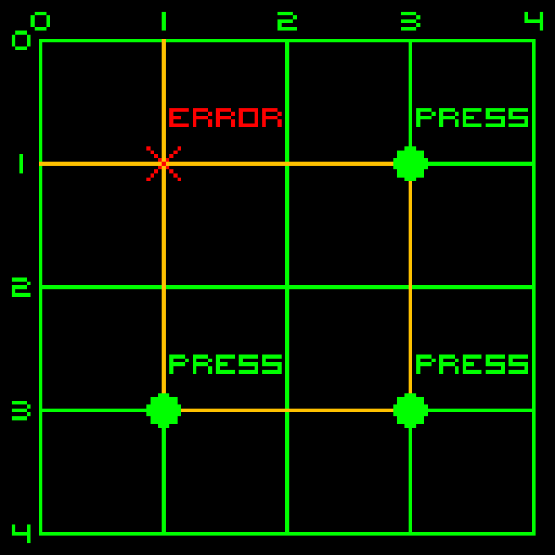
But there is a problem: if three keys are pressed together forming three corners of a square, a fourth, phantom (or ghost) key press will be detected at the missing corner. Here's a diagram to help explain that:
![]() In this example, keys are pressed at (c3,r1), (c3,r3) and (c1,r3), but when position 1,1 is scanned current will flow via the three pressed keys (orange line) and produce a phantom key press at (1,1).
In this example, keys are pressed at (c3,r1), (c3,r3) and (c1,r3), but when position 1,1 is scanned current will flow via the three pressed keys (orange line) and produce a phantom key press at (1,1).
This situation can be avoided by fitting a diode in series with each key switch. This means that current can flow from a row to a column but not the other way. Looking at the example above again, when (1,1) is scanned, current could flow from row 1 to column 3 at (c3,r1) but would not be able to flow onto row 3 at (c3,r3), so no circuit would be made.Most keyboards, including mine, do not do this and rely on detecting the phantom instead. This is quite easy to do: for each key, if two or more keys are pressed in same row and one one of those keys also has another key pressed in the same column then a potential phantom exists. Referring to the example above again, (c3,r3) would trigger phantom detection as it has a another key pressed in the same row at (c1,r3) and also in the same column at (c3,r1). When a phantom condition is detected, the scanning routine stops updating the state of the keyboard until the condition is cleared by releasing one of the keys.
Even with the phantom key problem, any two simultaneous key presses can be detected. As I'm building a thumb keyboard, and two is the usual number of thumbs per person, I think adding series diodes would be overkill in my case.
As this point we have the ability to determine which keys are pressed. In the next log I'll cover how this is turned into a series of key press, release and repeat events.
-
Keyboard Basics - Wiring
03/08/2019 at 21:17 • 0 commentsElectrically, a keyboard is just a grid of wires with a switch at each intersection. Pressing a key (switch) makes a connection between a single row and column. To read the keyboard, a controller energises the wires in one axis one at a time and checks each wire on the other axis for a circuit. If there is a circuit between a particular row and column then the key at that intersection is pressed (Probably, but I'll come back to that in another log).
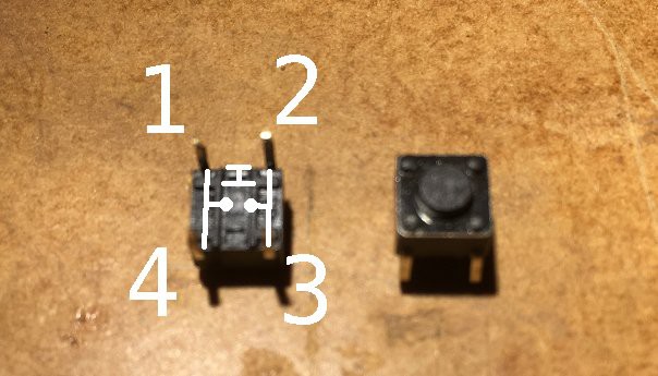
This is the back of my first prototype. Please excuse the terrible soldering and the fact that I totally missed a pin (which I've only just noticed). You can clearly see the row connections connected to the dark blue wires. The column connections are connected to the yellow wires. You don't see column wires running down the board because the columns are connected through the switches. The switches have two pairs of pins permanently connected:In the picture above, pins 1 is permanently connected to pin 4 and pin 2 is permanently connected to pin 3. Pushing the switch connects all four pins. This means that I can carry the column connections through the switch, bypassing the row wiring. A solder joint across two pads connects each row to the one below it.
Although my prototype has the keys laid out in a rigid grid, this is of course not usually the case with keyboards. Keyboards generally have their rows offset and include keys of different sizes, which sometimes cross multiple rows or columns. I don't think that different sized keys are practical with my design, but I want to look at offsetting the rows at some point. As this is meant to be a thumb keyboard, not a full sized one, I think that this is an acceptable compromise. -
Defining the Problem
03/05/2019 at 21:12 • 0 commentsRecently, I've been considering building something that would need a small thumb keyboard. I did consider modifying one of those mini bluetooth keyboards or a gaming chatpad but I couldn't find one that met my requirements, so I've decided to build one from scratch.
The requirements that I set myself are:
- Physical keys with tactile feedback (so touchscreens are out)
- Changing the layout and function of keys should be easy (as I will be experimenting with both)
- Should not require a custom PCB (although one could be used once a layout is chosen)
As you can see from the project picture, I've got as far as building a first prototype. I'll be talking about that more in another log soon.
My aim is to produce a flexible design and release the details in the hope that they will be useful to others.
 David Boucher

 A list of keyboard layouts in Linux Mint (just the 'A's).
 In this example, keys are pressed at (c3,r1), (c3,r3) and (c1,r3), but when position 1,1 is scanned current will flow via the three pressed keys (orange line) and produce a phantom key press at (1,1).