Taiwo
Taiwo-
Resuming The Project.
01/10/2020 at 19:36 • 1 commentI stopped developing Skrypt for a while due to my quite demanding school activities. Now, I am free for a long time and ready to put all of my effort into this.
PROBLEM FACED DURING PERIOD OF SILENCE.
Although, I was not posting here about my progress with the project, I have been quite busy with the hardware. My intention when I started this project was to learn what is to be learnt in the course of the project. I have not been disappointed. My PCBs failed woefully due to a couple of thing such as
- Poor Tools
- Poor PCB assembly skills
- Poor Design
- Latency between ordering of materials and receiving them.
It took me a while to get the hang of SMT reflow and assembly generally. I am glad I can do quite a lot now (Thanks FLUX). I got better tools and learnt better design and PCB assembly skills during the period of silence and I am quite confident.
It is quite apparent that I focused more on Hardware development than software/ firmware development during the period of "Radio Silence". This led to my decision to adopt a ready to use open source hardware for software development. This and the fact that my inadequacies should not hinder people that want to continue the project possibly on their own hardware.
CHOICE OF HARDWARE.
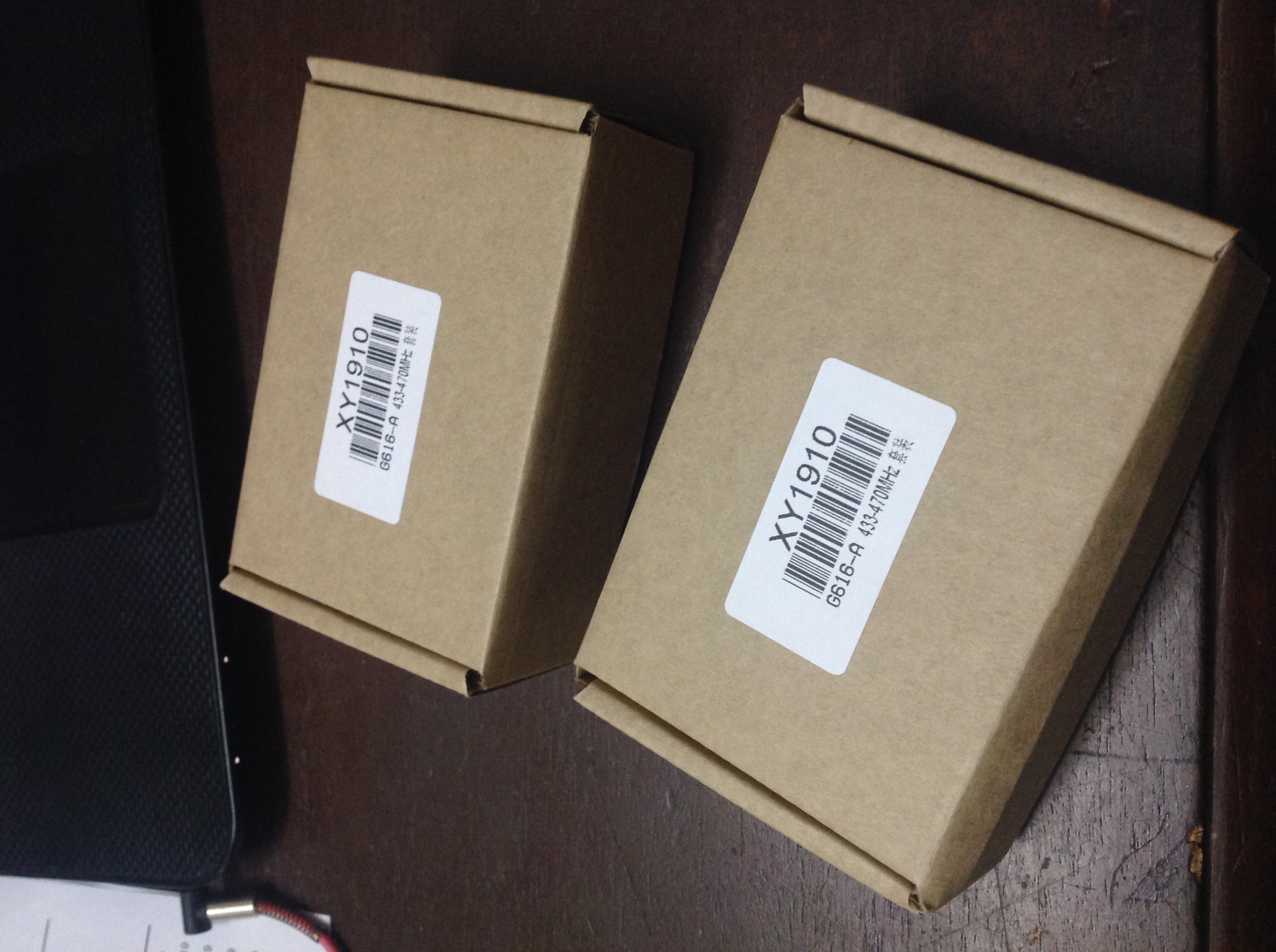
After surfing for a while, I noticed that there are quite a number of development boards that were designed for something like we are trying to achieve. I found a couple of TTGO LoRa based boards, Adafruit, Sparkfun and some other ones. What they all have in common is having an ESP32 chip connected to the LoRa chip on the same PCB. Nothing special. This coincided with the time when I was contacted by an official from Digitspace who expressed their wish to sponsor the project. Digitspace gave me a coupon and I spent the day perusing their huge catalog for an ESP32 LoRa Dev board and I found one with the name "LoRa 433MHz ESP32 OLED 0.96INCH BLE Wireless Module". It is basically a TTGO LoRa board that is well packaged and has a battery.
In a nutshell, it fits the base-band feature of the intended device that I set out to build. If you need to get started very quickly with no problems of connections and soldering, this is a great way to go.
![]()
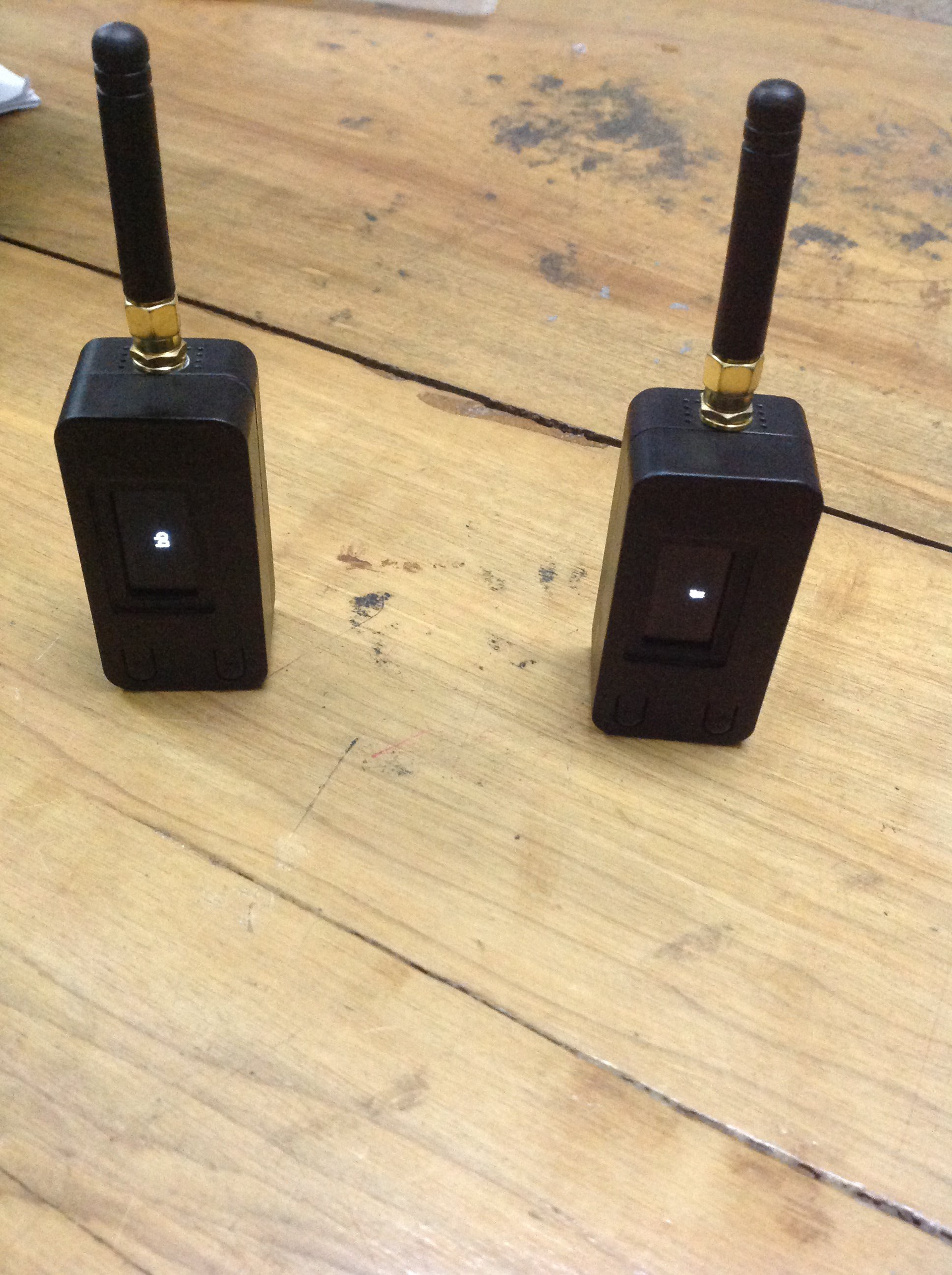
Each box actually contains a pair. It is quite good for a quick start. Check out the store. LoRa 433MHz ESP32 OLED 0.96INCH BLE Wireless Module
![]()
FIRMWARE DEVELOPMENT
This is a quite a developing aspect of the project. I wrote a basic Arduino sketch that just transmits and receives as requested by the user via Bluetooth. Its is a quite simple code that simply
- Listens for messages via the LoRa Chip interrupt pin
- Displays the messages on the appropriate output console.
- Send messages it receives via Serial Bluetooth.
- Set up an ID system for the device to know if the message is meant for it or not.
Making the ESP32 perform these tasks is not the hardest thing to do. With the help of several documentations and (of course) example codes, I completed the code and it worked quite well. I tested it on my PC and it worked. Then It happened.
The hardware is intended to be used with phones as well as PCs. I don't write android. At least not without the great help of the MIT App Inventor. So, I set out on a journey through the vast lands of the internet until I found BlueSPP. BlueSPP was the perfect temporary solution to my problem due to the following reason.
- It has a chat like interface for communicating with Bluetooth devices
- It stores messages
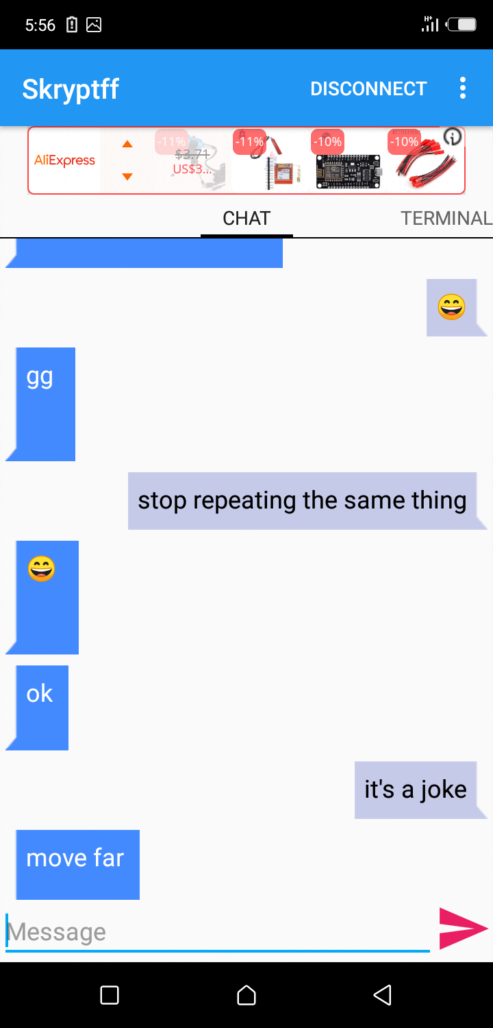
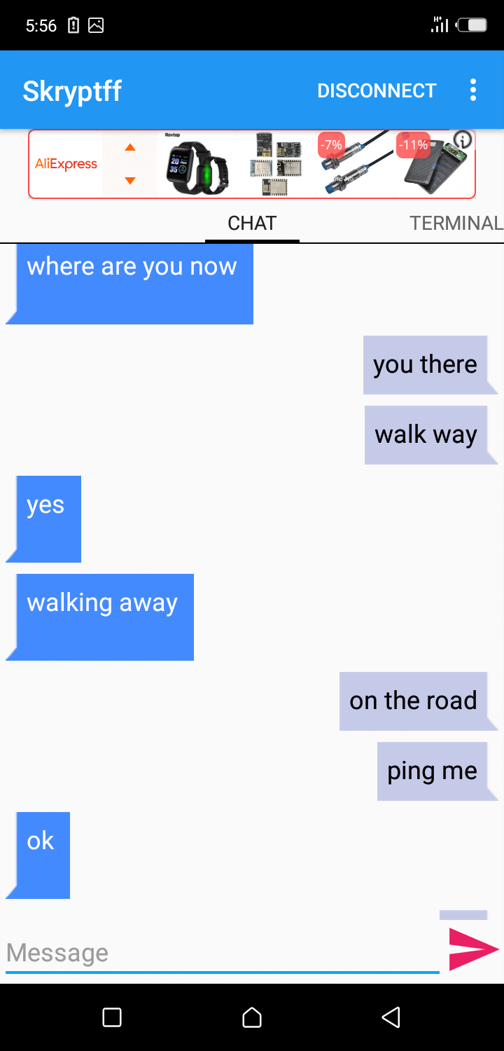
I settled for it as a temporary solution and it worked quite well. Here are some Screenshots of my phone running BlueSPP and communicating with Skrypt.
![]()
![]()
This was the messages that were exchanged between my friend and I while testing the range of the device. we covered like one Km with a lot of huge buildings between us. To be honest , it could be better. It does not seem like the dev board contains an LNA and our test ground is not as "Line of sight " as I would like it to be. I will test it again soon, this time, with actual figures.
I made a crappy video of the connection process.
Pro Tip: Use Full Screen to see details.
PLANS
I hope to
- perfect the software in the coming weeks to the best of my ability.
- make a mesh like self propagating network of such LoRa device with retransmission.
- find better Development boards that perform better.
- create a better hardware
If you know any board that is great for the application. Contact me.
If you possess any skill that might be of help to this project don't tarry to contact me. I could use some great help.
Thanks.
-
Change of project name.
07/16/2019 at 19:09 • 0 commentsI received an email today stating that the project name "LoraSleeve" needs to be changed as it contains LoRa which is a registered trademark of Semtech. This and some other things were the contents of the email. I had to change the project name to something not "LoRa" to avoid the project from being removed from the website.
So, here we are. Skrypt is the term that came to my mind immediately. Why ? I don't know myself. If another name pops up, I'll update appropriately. If you have a suggestion for a name, do well to comment and we'll review it together.
I have been a little busy these few weeks and I'll be back updating the project as it progresses. I have done some hardware tests with modules attached together and we seem to be on the right path.
There might be a need for an android application as I have been using BLE terminal apps and UART over USB OTG for my tests.
-
With Love from China.
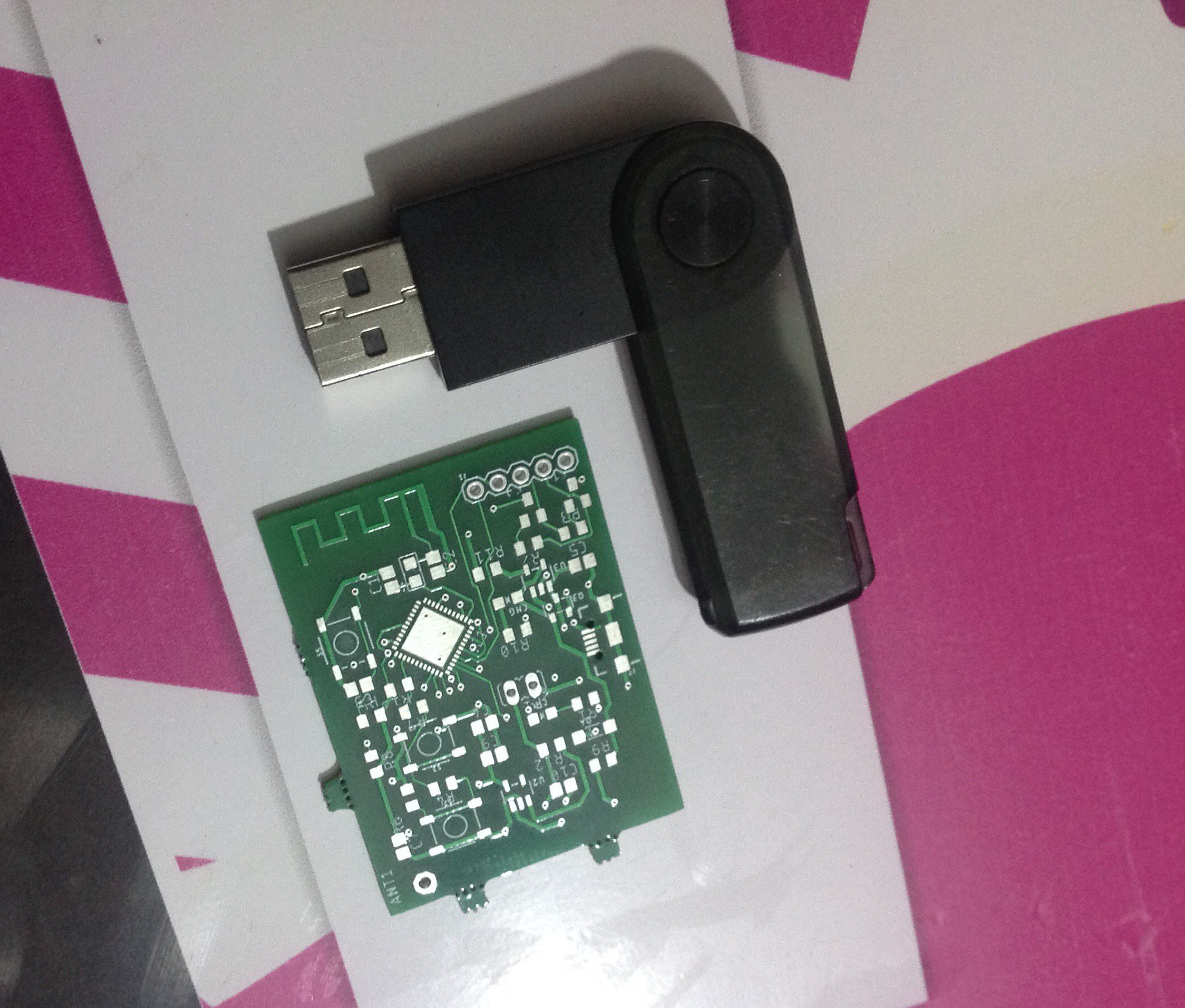
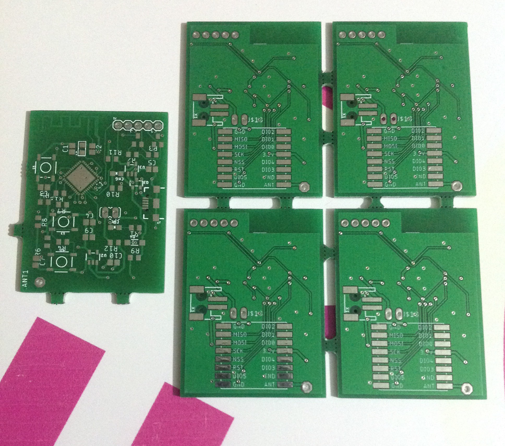
05/24/2019 at 05:23 • 0 commentsIt took quite a while for the PCB to arrive from China. Who knew China is that far away from here. The overall build quality of the PCB seems okay but I noticed a little problem. The board was a little bit bigger than what I had in my head and I added too much features for such low-power hardware.
![]()
![]()
It was probably due to the fact that it is my 4th board (noob alert) and I am still struggling to get my dimensions well. Also because I was a little too ambitious. At the end, I decided to
- Reduce the number of buttons drastically and allow tweaking of parameters via Wifi/BLE.
- Use ESP32 Wroom 32 for the next revision as they seem small enough for what I intend and I have(finally) experience soldering and troubleshooting them.
- Include a LNA and SMA antenna on the board without compromising its size. Probably a removable antenna or something similar.
- Make a repeater with better specs and to reduce the transmission time and power required by LoraSleeve.
- Find a way, if I can, to implement my own RFM96W on board. This does not seem very likely but who knows.
One important reason for switching to ESP32 Wroom 32 is its availability on Aliexpress compared to Esp32 Pico D4. And Aliexpress (3 weeks) seems to ship faster to my place than Lcsc (still waiting).
I am definitely not wasting 40 pieces of PCB (39 is okay). I will definitely populate at least one in the coming week ( when LCSC finally comes through) and will get started on the software.
I will make a log about the new schematic and layout soonest.
-
Ordering and Panelizing PCB
04/02/2019 at 06:26 • 3 commentsI have known about JLCPCB for a while and thought of giving them a try for this project. The PCB is a small one and to save money I thought of panelizing the PCB. I'll have more PCBs for the same price. YAY. There was only one problem, I had no idea how to go about it. I went off to google and searched. I got a couple of cool options. Some easy and others not so easy.
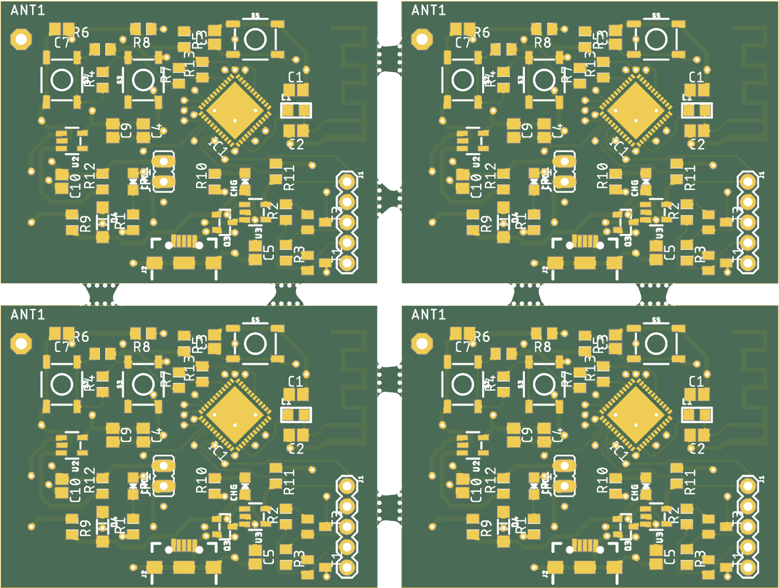
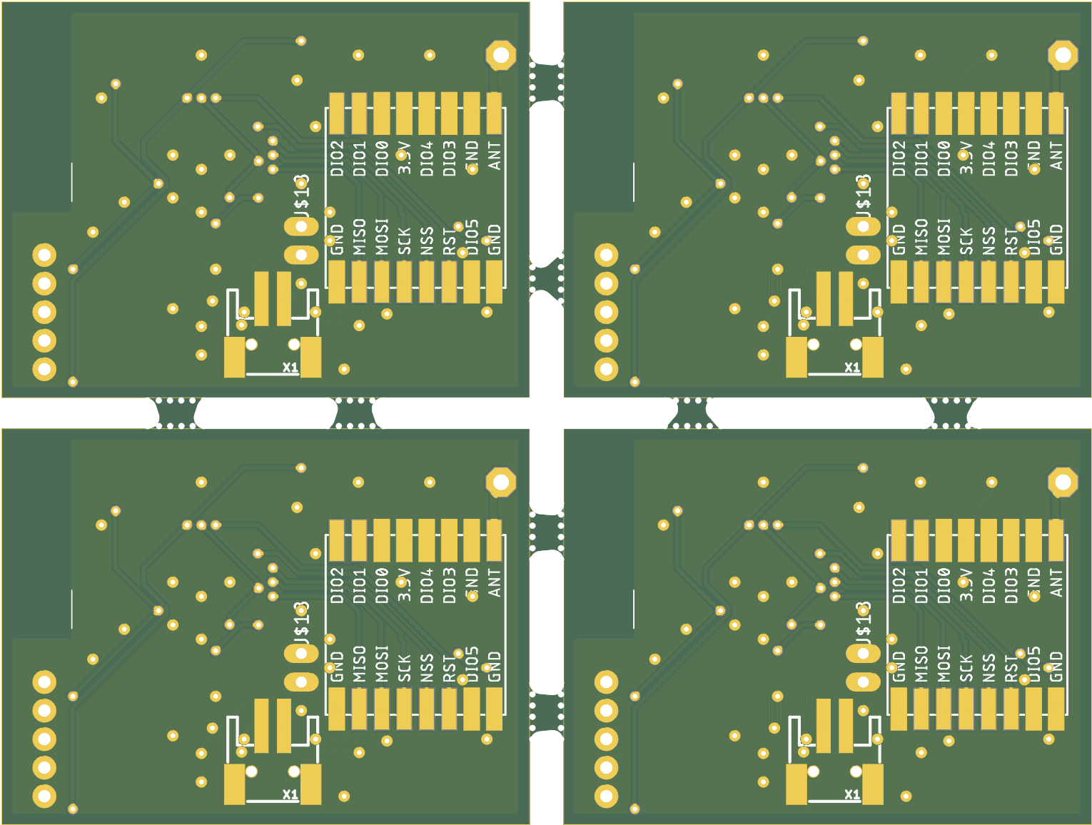
After deliberating with google and very helpful guys on the HackChat, I settled for GerberTools (https://github.com/ThisIsNotRocketScience/GerberTools/releases). This awesome application has a cool GUI and quite efficient gerber Panelizer. I took me a while to get the hang of it for I had dimensioned my board on the copper layer (yeah, who does that?). I finally got it to work by removing the dimension and using DirtyPCB's cam files on eagle after it turned out that the app was no fan of the .gbr format. Below is the result I got after panelizing
![]()
![]()
Notice the absence of traces in the bottom layer. Thats a bug I hope the maker of the gerber viewer fixes. I displayed it quite well on JLCPCBs gerber viewer though. Well, I am sure the PCB is very well on its way down and will be available in a few weeks.
NB. I'll update the PCB file again (Sorry)
-
Finishing Up and Cleaning Up
03/18/2019 at 11:37 • 0 commentsCORRECTION AND CHANGES TO SCHEMATIC.
It took a while for me to notice a "little" error in the previously posted schematic. I missed a pull up resistor for the buttons and misspelled some net names . Fortunately, I noticed it before starting the layout of the PCB. In my bid to correct the mistake, I thought it wise to review the components used with the device and made the following changes.
- I removed the OLED in a bid to reduce the power consumed and since all that it display could be inferred by other means (via LED and the PC/smartphone itself).
- I reduced the number of buttons to two.
- I added another LED for power and connection indication.
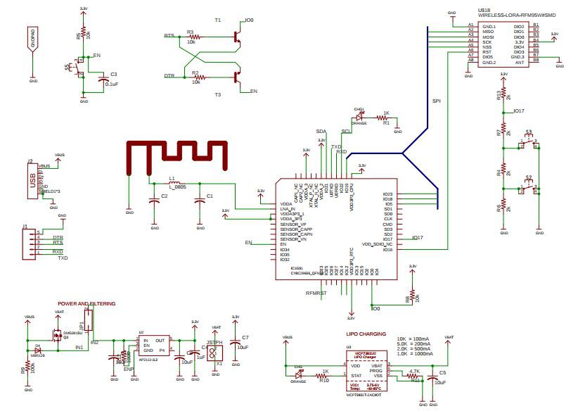
![]()
PCB LAYOUT.
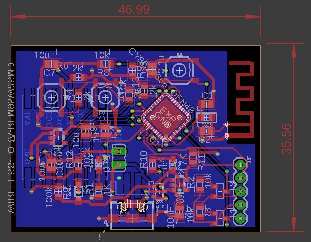
I began laying out the components on the board with the aim of making the PCB as small as possible. There was a limit to its size as I used 0805 components for easy hand soldering ( I can't cope with smaller components ,YET ). I used the ESP32 Pico D4 chip for smaller size. The PCB measured 5 cm by 3.6 cm at the end.
![]()
The new schematic and layout has been uploaded in the project page. Off to JLCPCB...
-
Let's Begin
03/14/2019 at 16:50 • 0 commentsSO FAR...
When I created this project page, I had no LoRa module at hand . I still don't, but I had to get started. I checked my stash of unused components, and found a pair of NRF24L01.
An RF transceiver, that is not LoRa.
I played around with its transmission and reception of messages. I used Serial via the Android Arduino application serial console on both phones. It worked, not well enough, but enough to prove a point.
My Android development skill is close to non-existent, and I hope to use Thunkable to make an app that interfaces with the ESP32 Bluetooth and sends and receive message from the hardware.
PCB DESIGN
I began making the schematic diagram early this morning. The device was to have
- A small screen to display basic information like battery level, number of connections etc.
- A rechargeable battery
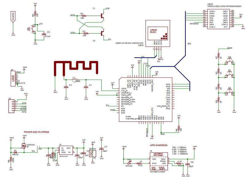
I used 0805 components and the ESP32 Pico D4. The PCB layout is not complete and I thought I'd share the PDF of the schematic.
This is the progress so far.
![]()