Actually I have very nearly completed this project, I will add further details and update this as time allows.
0%
0%
Tacx Flow Ant+ Conversion
Upgrade a Tacx Flow cycle turbo trainer to support Ant+
Become a Hackaday.io member
Already have an account? Log in.
Just one more thing
To make the experience fit your profile, pick a username and tell us what interests you.
Pick an awesome username
hackaday.io/
Your profile's URL: hackaday.io/username. Max 25 alphanumeric characters.
Pick a few interests
Projects that share your interests
People that share your interests


 Jesse R
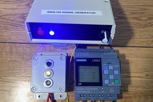
 Tom Goff
 Nitesh Kadyan
 esieapstvelo
The project works, I have not worked in this in 3 or 4 years. I have uploaded all files needed to build it. I don't get on here often, but drop me a msg if there are any questions.