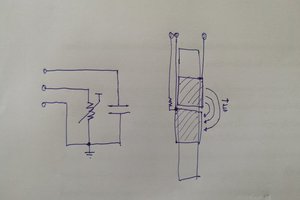
I drew a lot of inspiration from Marco Reps video Hi-Res Pressure Sensor Matrix with the LattePanda when I started this project. Since our application requires a much smaller matrix, we decided to use a flex PCB to arrange the sensor lines and interface connectors. There are several choices in the market for piezoresistive material. We selected Velostat and one other type as our starting point. The components of the sensor matrix are shown in the image below - note that both piezoresistive samples are shown, only one at a time is sandwiched between the pair of flex PCBs.
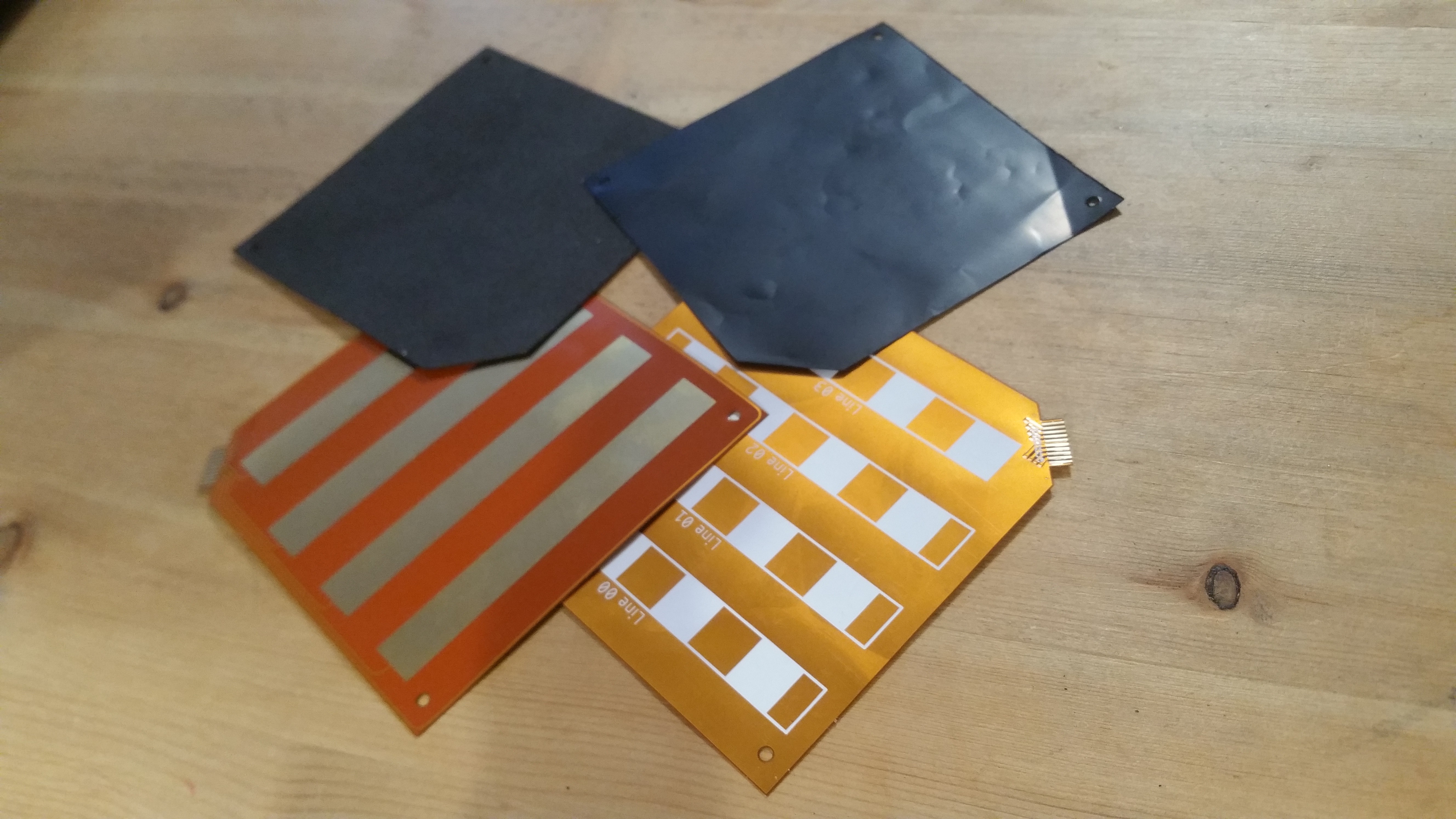
Since cost was a concern, I looked for a way to have a single flex PCB serve as the top and bottom of the matrix. The solution was to put the connector fingers symmetrically on the diagonal on both sides of the PCB with only half of the fingers

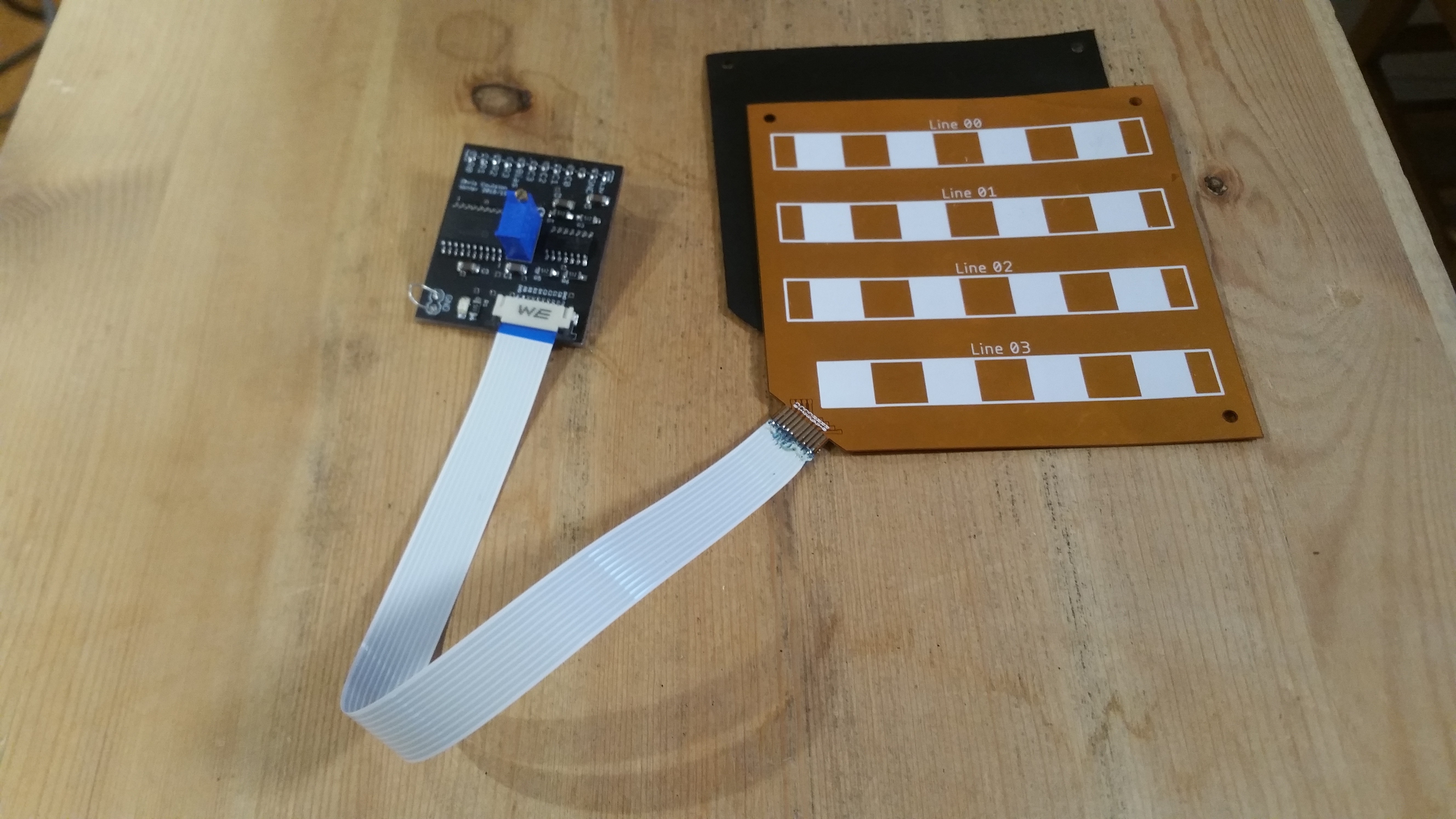
In order to measure the resistance a little analog wizardry is needed in the form of an interface board. This is shown in the image below.
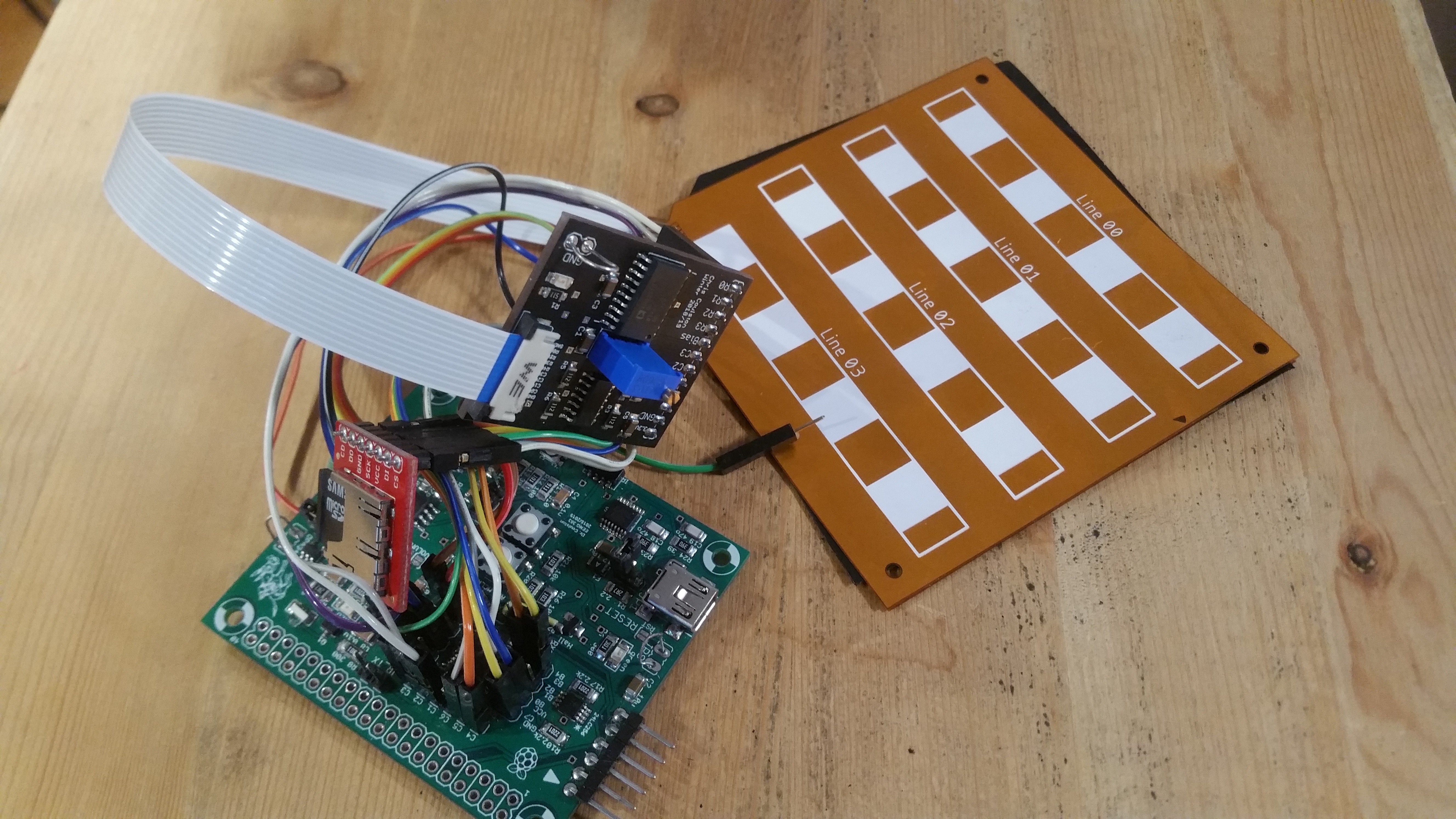
Once we got the interface board operational, I connected it to a PIC 18F26K22 development board that I use in my classes. With the accompanying SD-card we can record days worth of pressure sensing data. The image below shows the completed prototype.
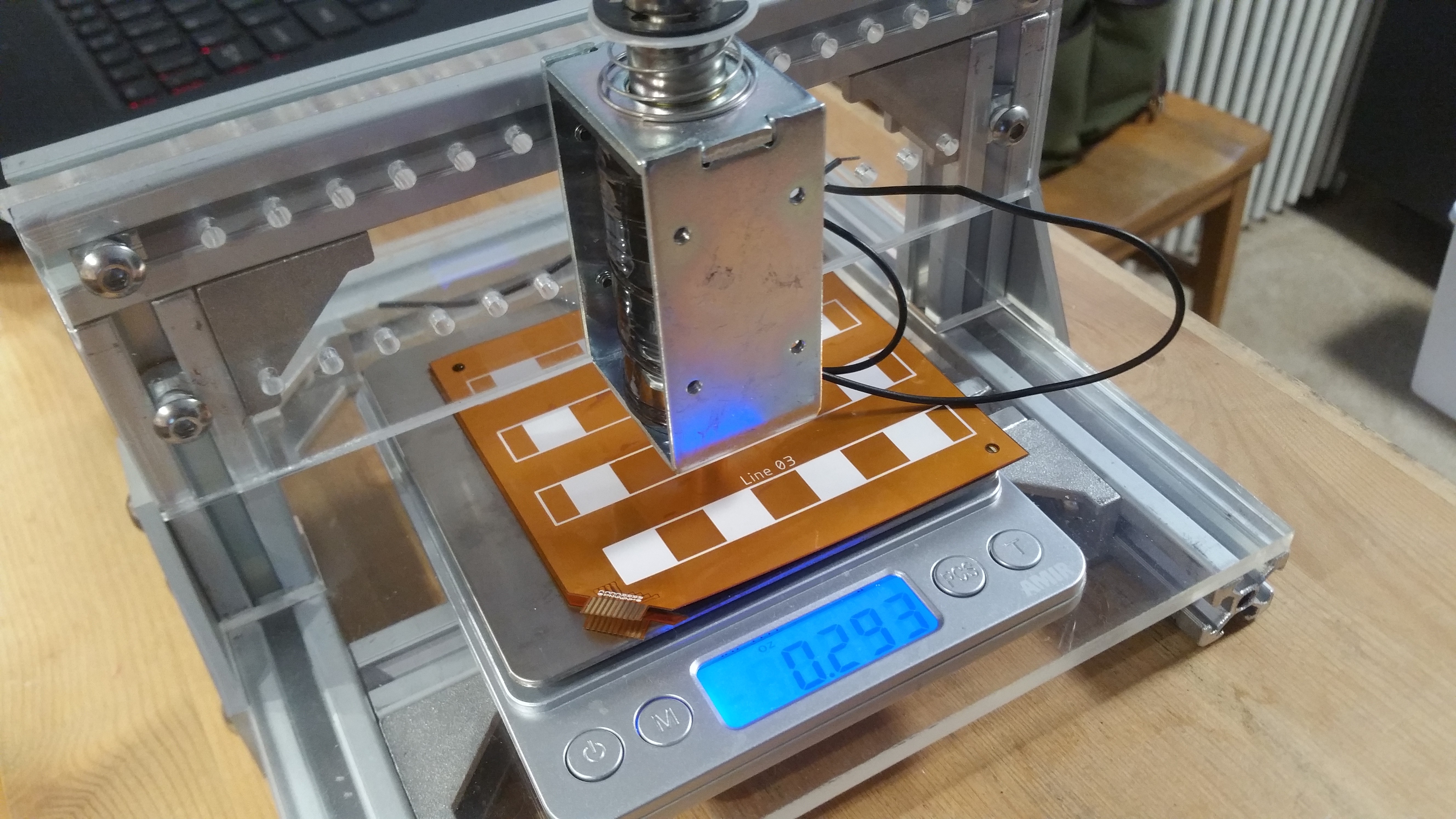
One of my main objectives is to characterize the frequency response of the sensor elements so that we know the bandwidth and consequently know what phenomena we can reliably observe. In order to accomplish this, I built a small testing platform from 2020 series T-Slot Aluminum Extrusion and laser cut acrylic. The solenoid is actuated with an external circuit. Using the scale below the sensor matrix and the size of the solenoid head, we can determine the pressure being applied to the matrix. This allows us to convert the resistance readings into PSI.
 chris.coulston


 ohmohm
 Anas Raza Khan
 DIY GUY Chris
 Nelson Phillips
My wife is a physical therapist and asked me to do something like this last week. II came up with something of a 1 point sensor using Velostat, but multiple points like this is ideal.
One of the first things to pop up in search for something similar was this project. Where did your pcb come from? I understand you designed it but was it made in house or ordered?
Her application is determining the pressure applied by feet inside a shoe when the patient is told not to bear weight on it due to their condition, and then use that to provide perhaps audio/visual feedback to get them to stop. Something this thin would be perfect inside of a shoe and not really be noticeable to the wearer. I was thinking of having it for use in a clinical application, where it could connect to the local network and log the data so that the clinician can provide real-time feedback to the patient, in addition to the audio visual feedback, such as a rumble motor /or blinky light.