Introduction
I wanted to see how far I could push the Cortex M0+ of the Arduino Zero. I think it is a balanced microcontroller: not too limited like an AVR, not too fancy, like a Cortex M4 (which has enough computing power even to run Doom).
I wanted to do something that could be challenging and, at the same time, funny. Well, I love 2D platform games. Why not starting from them?
Even if 2D platform games might seem outdated, they still require a good amount of memory, and if no hardware 2D acceleration is present, all the data must be processed by the CPU or, if present, by the DMA.
Initially I went on the conservative way: the ATSAMD21 specifies a maximum SPI frequency of about 12MHz, and by specification, the ST7735 controller allows a maximum SPI frequency of 15MHz (66ns SCLK time). Therefore I set the SPI frequency to 12 MHz and I also fixed the frame rate to 25 fps (without cap, the refresh frequency fluctuated from 28 to 33 Hz. I wanted to save a couple of fps because I will need to implement the sound later).
However I have recently realized that both the display and the ATSAMD21 can work at 24 MHz! That's a good overclock amount! (still the CPU is not overclocked!)
Now, the uncapped frame rate goes up to 51 fps, and, with capping a constant 40-fps frame rate can be achieved!
Specifications achieved so far:
- Resolution: 160 x 128 pixel
- Color depth: 16 bpp
- Dual playfield with parallax scrolling
- Up to full-screen overlay for score/life
- Multiple on-screen sprites.
- Frame rate: minimum 40 fps using an out-of-spec 24 MHz SPI frequency value. Using a 12 MHz SPI, we can achieve more than 28 fps.
The hardware:
The hardware is composed by three boards.
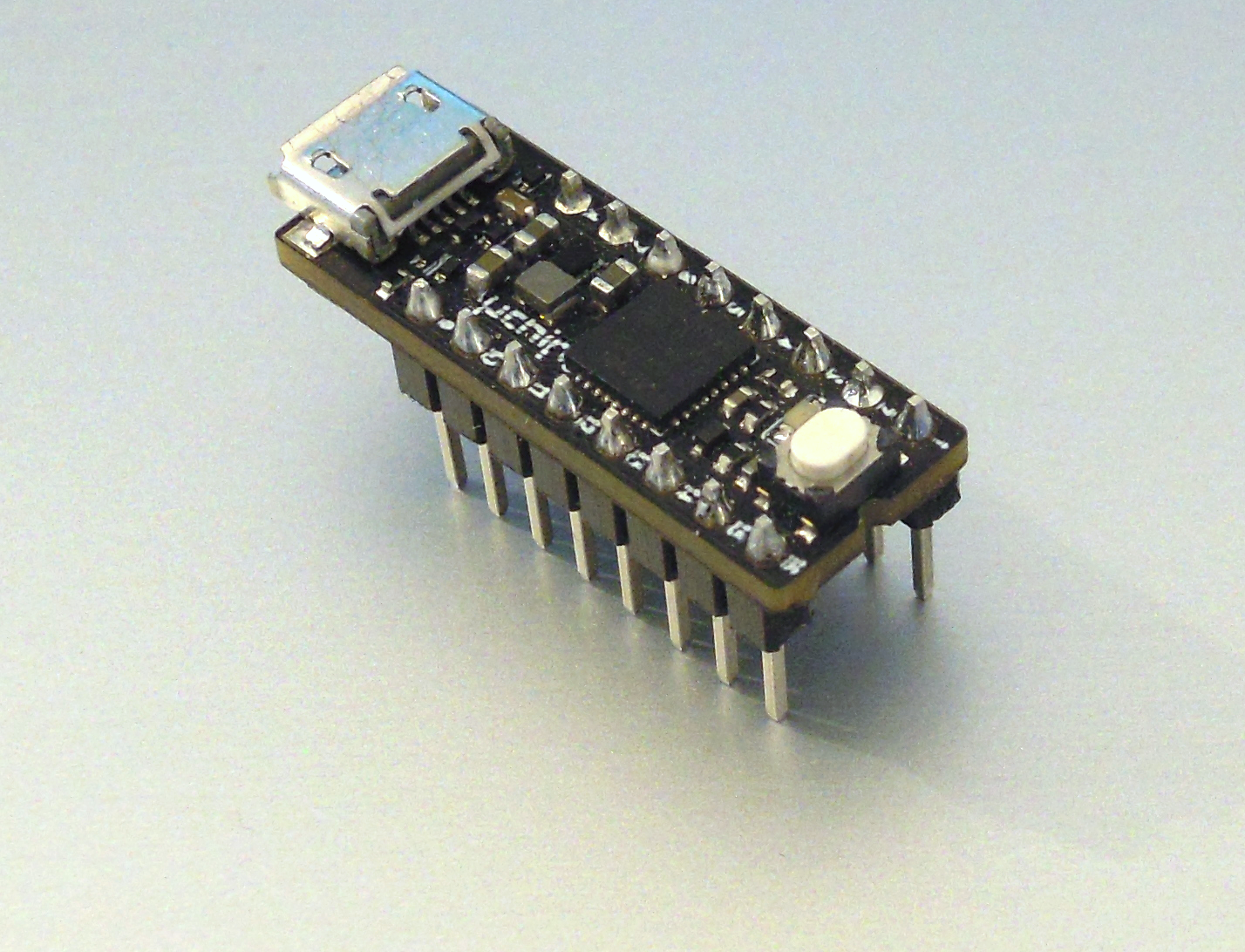
- The main core of this project is uChip, which is basically an Arduino Zero compatible board shrunk to a 16 DIP board (https://www.kickstarter.com/projects/1186620431/uchip-arduino-zero-compatible-in-a-narrow-dip-16-p). All the magic happens inside it, by software. Its MCU is an ATSAMD21, running at 48 MHz, featuring also a DMA engine.

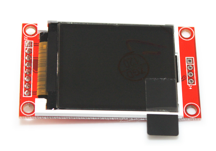
- Then there is of course the TFT LCD. I chose a 1.8” SPI 160x128 TFT module, with SD card slot (which might be useful to store audio samples and music). The controller of that particular module is an ST7735. I verified that the ILI9341 modules work too, without software modifications. As you can see, by default they come without the right side header soldered on them. You must solder it.

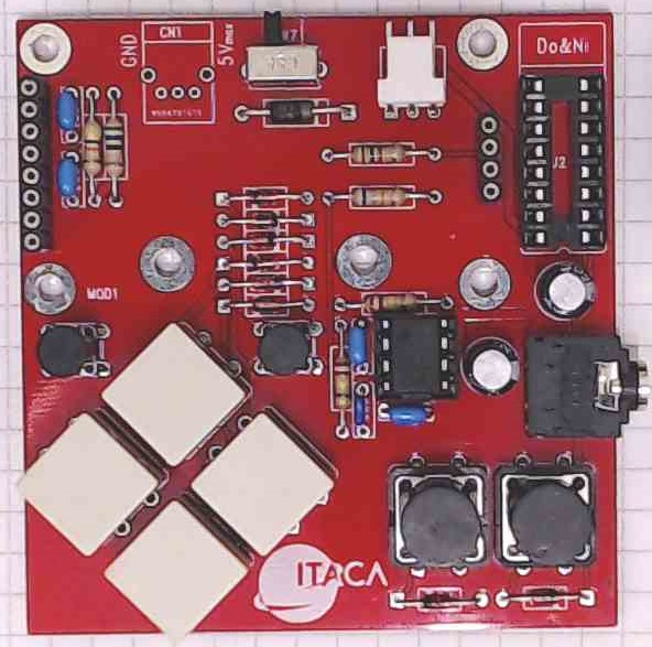
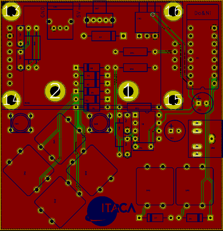
- And well, to play a game you’ll need some sort of input, something like a gamepad! I decided to implement a 8-key gamepad. These are placed on the carrier board, which hosts also few passive components and an 8-DIP IC, which is an operational amplifier for the earpieces. The op amp is connected to the 10-bit DAC output of the ATSAMD21.

The power can be provided either through the micro USB connector of uChip, or externally, for instance using 3 AA/AAA batteries.

The board layout and schematics will be available in KiCad format (a popular free PCB CAD program).
Preliminary considerations
Before jumping head-first into the project let’s make some rough estimations. Is it feasible?
Computing Power. Enough?
Yes, the ATSAMD21 is quite powerful. Enough powerful? It is a 48 MHz Cortex M0+, with a good DMA engine. Let’s make a ballpark calculations. The 48MHz frequency means that we have about 93 clock cycles per each pixel, at 25 fps....
Read more » Nicola Wrachien


awesome!