Introduction
I wanted to see how far I could push the Cortex M0+ of the Arduino Zero. I think it is a balanced microcontroller: not too limited like an AVR, not too fancy, like a Cortex M4 (which has enough computing power even to run Doom).
I wanted to do something that could be challenging and, at the same time, funny. Well, I love 2D platform games. Why not starting from them?
Even if 2D platform games might seem outdated, they still require a good amount of memory, and if no hardware 2D acceleration is present, all the data must be processed by the CPU or, if present, by the DMA.
Initially I went on the conservative way: the ATSAMD21 specifies a maximum SPI frequency of about 12MHz, and by specification, the ST7735 controller allows a maximum SPI frequency of 15MHz (66ns SCLK time). Therefore I set the SPI frequency to 12 MHz and I also fixed the frame rate to 25 fps (without cap, the refresh frequency fluctuated from 28 to 33 Hz. I wanted to save a couple of fps because I will need to implement the sound later).
However I have recently realized that both the display and the ATSAMD21 can work at 24 MHz! That's a good overclock amount! (still the CPU is not overclocked!)
Now, the uncapped frame rate goes up to 51 fps, and, with capping a constant 40-fps frame rate can be achieved!
Specifications achieved so far:
- Resolution: 160 x 128 pixel
- Color depth: 16 bpp
- Dual playfield with parallax scrolling
- Up to full-screen overlay for score/life
- Multiple on-screen sprites.
- Frame rate: minimum 40 fps using an out-of-spec 24 MHz SPI frequency value. Using a 12 MHz SPI, we can achieve more than 28 fps.
The hardware:
The hardware is composed by three boards.
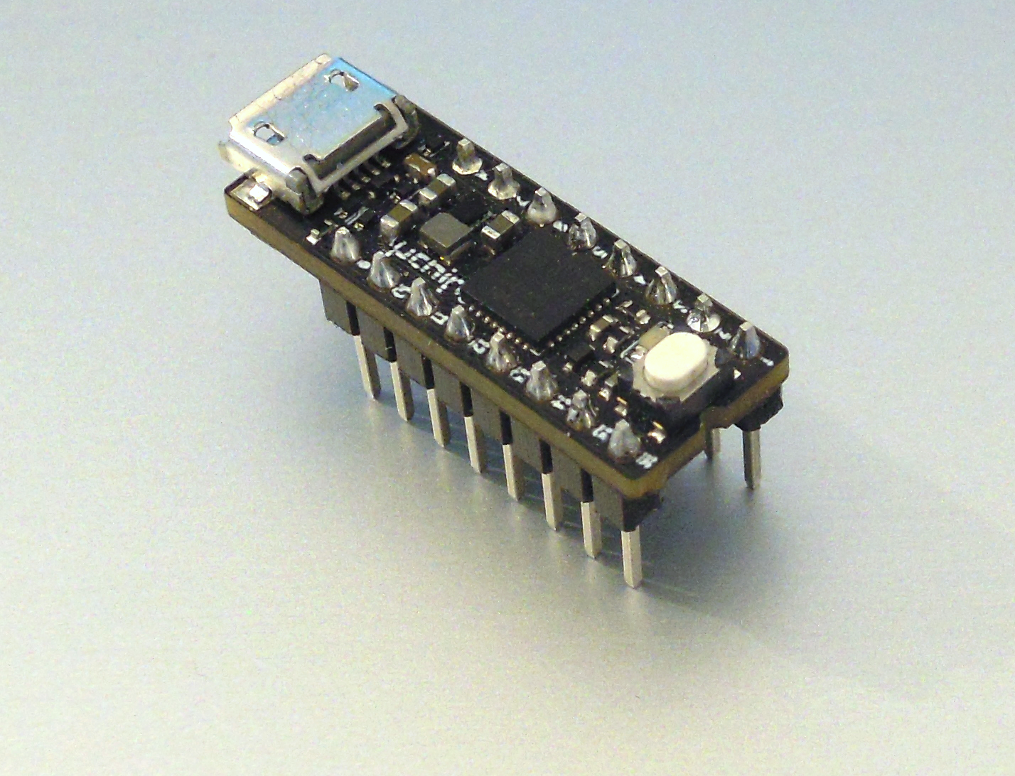
- The main core of this project is uChip, which is basically an Arduino Zero compatible board shrunk to a 16 DIP board (https://www.kickstarter.com/projects/1186620431/uchip-arduino-zero-compatible-in-a-narrow-dip-16-p). All the magic happens inside it, by software. Its MCU is an ATSAMD21, running at 48 MHz, featuring also a DMA engine.
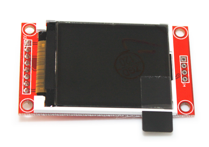
- Then there is of course the TFT LCD. I chose a 1.8” SPI 160x128 TFT module, with SD card slot (which might be useful to store audio samples and music). The controller of that particular module is an ST7735. I verified that the ILI9341 modules work too, without software modifications. As you can see, by default they come without the right side header soldered on them. You must solder it.
- And well, to play a game you’ll need some sort of input, something like a gamepad! I decided to implement a 8-key gamepad. These are placed on the carrier board, which hosts also few passive components and an 8-DIP IC, which is an operational amplifier for the earpieces. The op amp is connected to the 10-bit DAC output of the ATSAMD21.
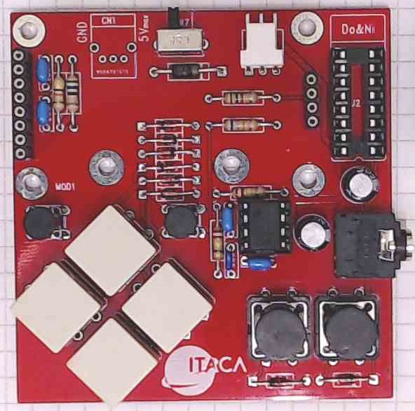
The power can be provided either through the micro USB connector of uChip, or externally, for instance using 3 AA/AAA batteries.
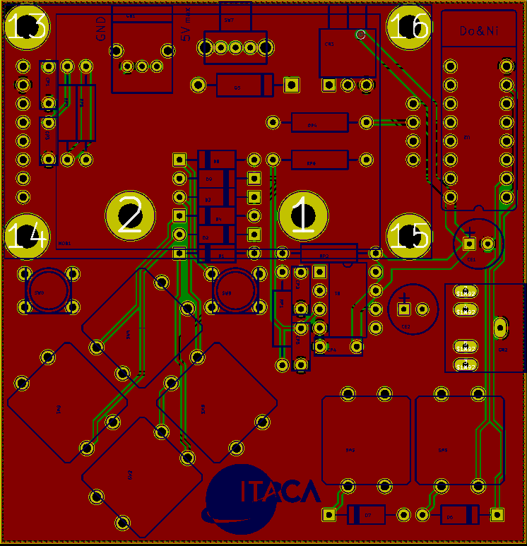
The board layout and schematics will be available in KiCad format (a popular free PCB CAD program).
Preliminary considerations
Before jumping head-first into the project let’s make some rough estimations. Is it feasible?
Computing Power. Enough?
Yes, the ATSAMD21 is quite powerful. Enough powerful? It is a 48 MHz Cortex M0+, with a good DMA engine. Let’s make a ballpark calculations. The 48MHz frequency means that we have about 93 clock cycles per each pixel, at 25 fps. In these cycles we can use both the CPU and the DMA (unless they access the same memory/resource). Each pixel is 16 bit, but both CPU and DMA can make 32 bit accesses. Therefore the initial goal of 25 fps was definitely achievable! We will see later that 40 can be also achieved!
Memory considerations - RAM.
A 160x128 pixel frame, at 16 bpp has a memory requirement of 40 kB. There is no way we can fit that framebuffer on the 32kB RAM of the ATSAMD21.
This can be easily overcome by noticing that we actually do not need to store the entire frame on the MCU’s internal RAM (why should we anyway?). We will generate our image data as the series of many horizontal stripes. For instance, we can consider a 16-pixel wide horizontal stripe buffer, and write on it. After we finished generating all the data on that stripe, we send the data to the display.
We said that CPU and DMA can work at the same time. Therefore, to optimize everything we won’t use only one buffer. In fact, when the buffer is sent (via DMA) to the display’s SPI, we can write on another buffer, and generate the next horizontal stripe (which will be sent again via SPI).
Memory considerations - FLASH.
We want our level to be very huge. Many horizontal screens, by many vertical screens. Let’s say 10x10! This would imply 40kB x 100 = 4 MB of flash memory just for the “image” of the level.
Of course we won’t use this naive technique. Each level will be made of a limited number of different square tiles (e.g. 128 tiles), which can be combined to create the environment. This drastically reduces the memory usage. We will use 16x16 pixel tiles @ 16 bpp (512 bytes per tile). The map of the level will consist of a bidimensional array, in which, each element indicates which tile should be placed at a particular position.
Display SPI port bandwidth.
To get 25 fps, we need a 160 (width) x128 (height) x 16 (bpp) x 25 (fps) speed in terms of bits per second. This is about 8MHz. Both the specs of the ST7735 and the ATSAMD21 handle such speed. Actually we can also go up to 12 MHz without problems, as the ST7735 has a maximum 15 MHz SPI clock value, and the ATSAMD21 has a maximum SPI frequency of 12 MHz. Still I recently discovered that a 24MHz SPI works too! With 24 MHz the maximum frame rate would be just under 75Hz!
Other considerations
Using DMA for just the SPI would be a waste of resources. In fact we said that we will go at only 12 or 24 MHz. Since the SPI sends one bit per clock cycle, its data register must be updated by the DMA every 8 bits, i.e. with a frequency of 1.5 or 3 MHz. In terms of CPU clock cycles, one time each 32 or 16 cycles. Therefore, the DMA would sit and do nothing (actually it must perform other tasks) for the majority of its available time.
Therefore, when possible, we will use DMA not only to send data to the display, but also to draw graphics. The background graphics is a good candidate to be drawn by DMA. Partially transparent tiles (i.e. tiles with at least one transparent pixel) will be considered as sprites and won't be drawn by DMA.
Sprites, instead, being partially transparent, will be drawn by the CPU.
As you will see, intensive use of DMA and multiple buffering are the key elements for this project. Furthermore, an optimized storage of the graphics elements is required, to fully exploit the capabilities of the DMA engine of the ATSAMD21, and reduce the DMA controller overhead.

Map editor
A map level editor is mandatory. While there are some good tools already made on the net, they all miss something. In particular we want to export the map, the sprite positions, sprite data, and tile data in a way which is optimized for our hardware setup.
For this purpose I made a java-based application, that allows you to create a map, place sprites, and set the behavior of each tile. The editor allows you to export the various data in a way which is optimized for our purpose.
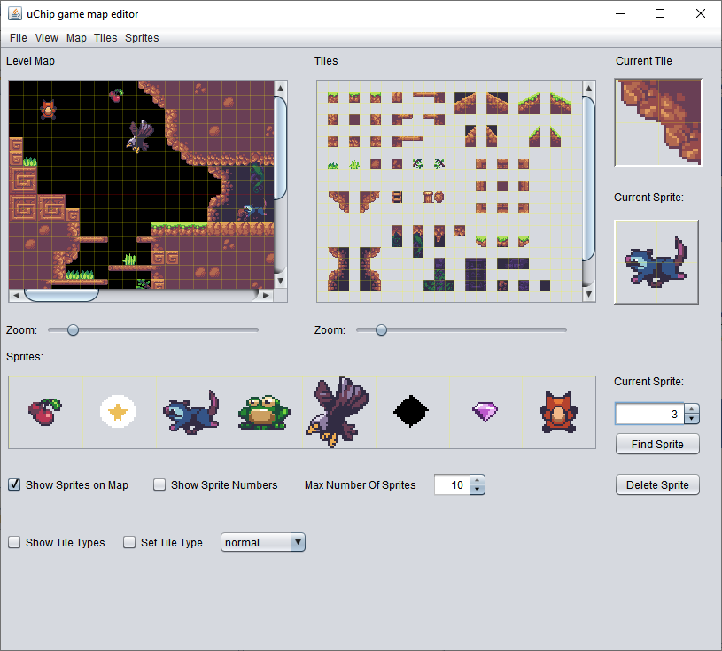
Current status
Here is a video of the current status running at 40 fps. The in-game timing should be slowed down by a factor 25/40 (i.e. the gravity factor, the delay between each sprite frame, the speeds of enemies and player). In fact, using the conservative 12MHz SPI, the frame was set to just 25 fps. Now the SPI runs at 24 MHz and the frame rate is fixed at 40 fps.
The full source code and better detailed explanation is available here: https://next-hack.com/index.php/2019/04/07/lets-build-an-handheld-platform-game-with-a-cortex-m0-microcontroller/
 Nicola Wrachien