 Grant Giesbrecht
Before jumping into designing the filters for the equalizer, I wanted to take some measurements of different passive filters' frequency responses. The goal was twofold: 1.) I worked out some formulas for predicting the transfer function of passive filters. These measurements can validate these models so I know I can apply the same analysis techniques to the more complicated filters to come. 2.) These passive filters give me something against which I can compare my later filters.
First I looked the classic RC low pass and high pass filters. I threw circuit together on a breadboard and set specific input frequencies into the circuit with my waveform generator, then recorded the gain with my oscilloscope. I made the theoretical curves very simply just using complex impedances to analyze the 3-node circuit. I then tested a band-pass filter by putting a low-pass and high-pass filter in series with an op-amp in between. The op amp was set to a unity-gain configuration to make sure the circuits behave the same way as when they were separate.
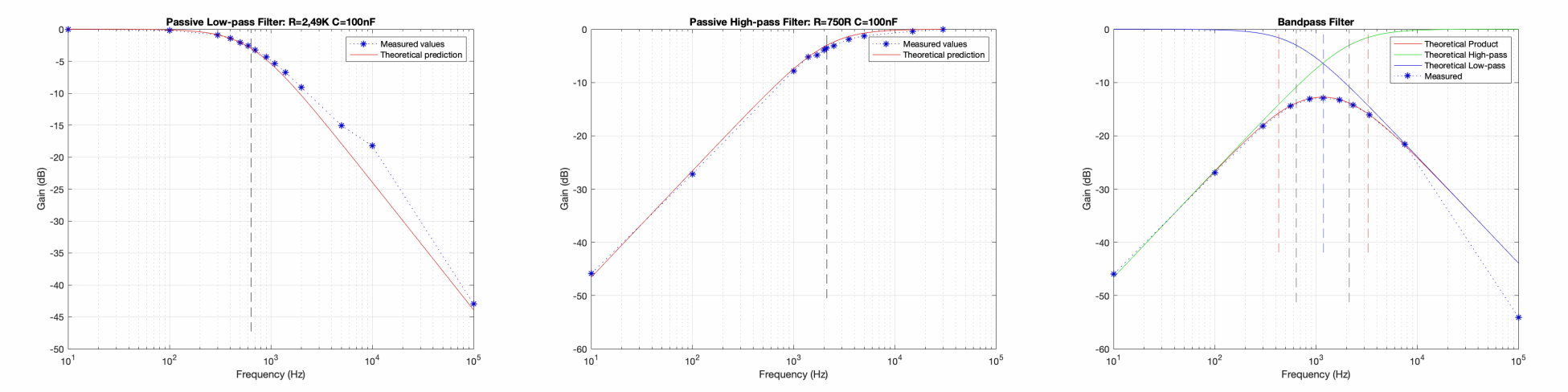 As you can see in the figures above, everything matched up pretty well.
 Next up was to remeasure the frequency response of my equalizer from my earlier project, GEQ-1. This was more than a bit tedious because each of the three bands had to be measured at both maximum and minimum gains, resulting in a total of 7 data sets (the 7th comes from a baseline in which all stages are set to have a flat response).
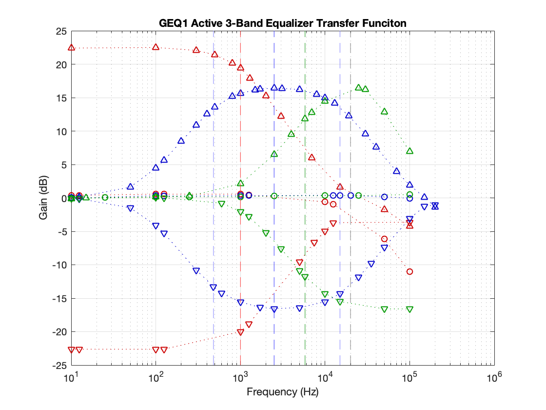
The graph above shows what I measured. The red curves indicate when the low-band was set to either maximum or minimum gain (up-triangle markers indicate max, down-triangle markers indicate min), blue indicates mid-band, and green high-band. I don't like the drop-off in gain at high frequencies, the low-Qs, and the uneven max gains between different bands. These are issues I'll address with my new equalizer.
Discussions
Become a Hackaday.io Member
Create an account to leave a comment. Already have an account? Log In.