-
1Parts
To make this you will need an ESP32 board or an ESP8266 and you can also add a battery if you want.
I used firebeetle LoRa board of 915MHz frequency. DFRobot offers 3 types of boards depending on the frequency that is legal in your area:
1) 433MHz
2) 868MHz
3) 915MHz
For the display, I used an OLED shield.
I suggest using boards from DFRobot with this module as the pinout will be compatible and you will face no issues anywhere.
-
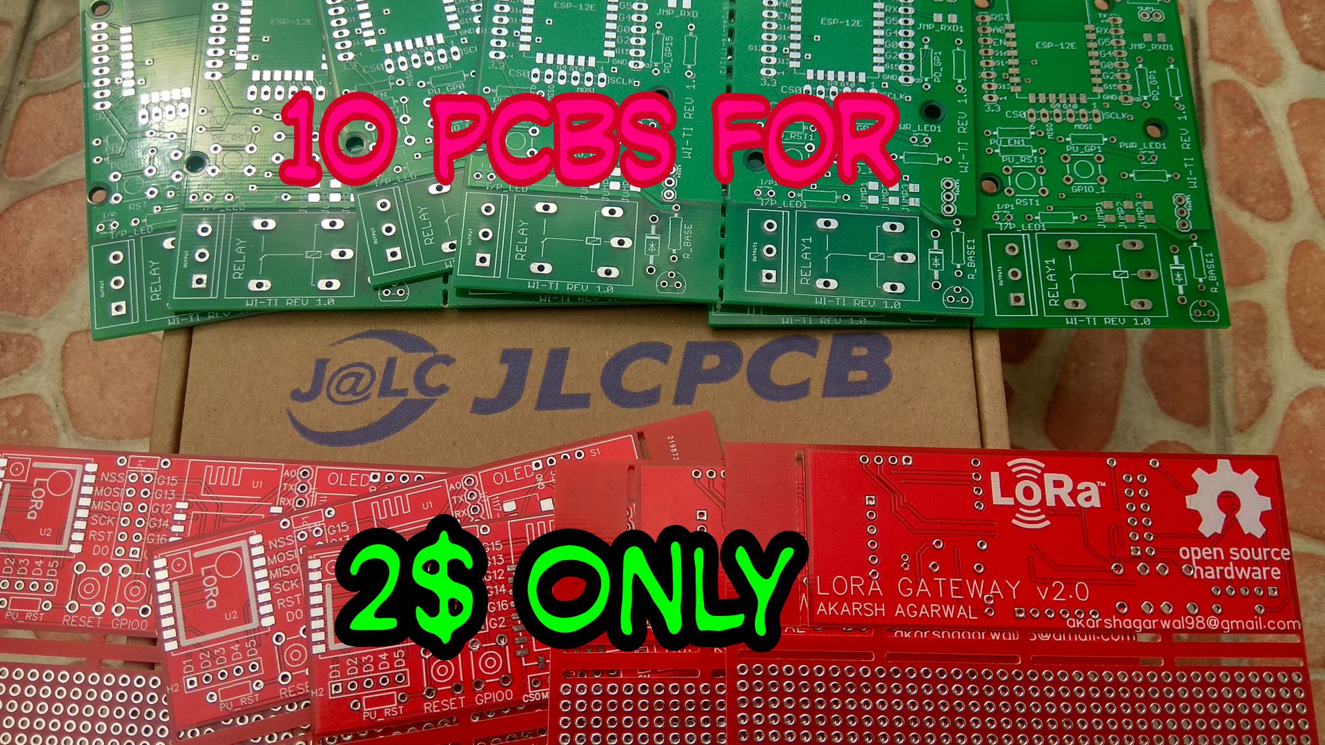
2Get PCBs for Your Project Manufactured
![]()
You must check out JLCPCB for ordering PCBs online for cheap!
You get 10 good quality PCBs manufactured and shipped to your doorstep for 2$ and some shipping. You will also get a discount on shipping on your first order. To design your own PCB head over to easyEDA , once that is done upload your Gerber files onto JLCPCB to get them manufactured with good quality and quick turnaround time.
-
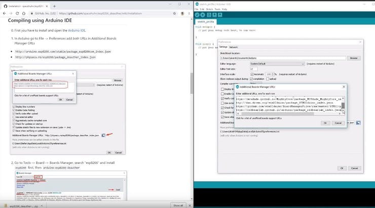
3Download and set up the Arduino IDE
Download the Arduino IDE from here.
1. Install the Arduino IDE and open it.
2. Go to File > Preferences
3. Add https://dl.espressif.com/dl/package_esp32_index.json to the Additional Boards Manager URLs.
4. Go to Tools > Board > Boards Manager
5. Search for ESP32 and then install the board.
6. Restart the IDE.
-
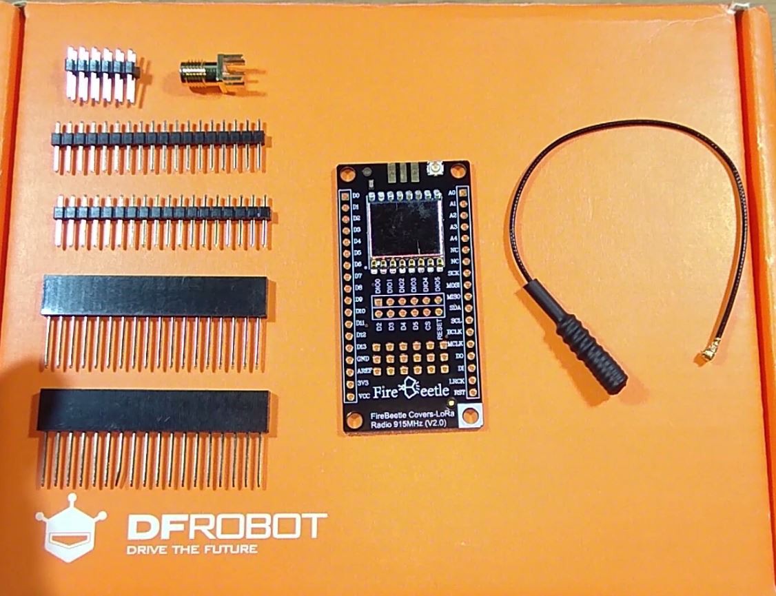
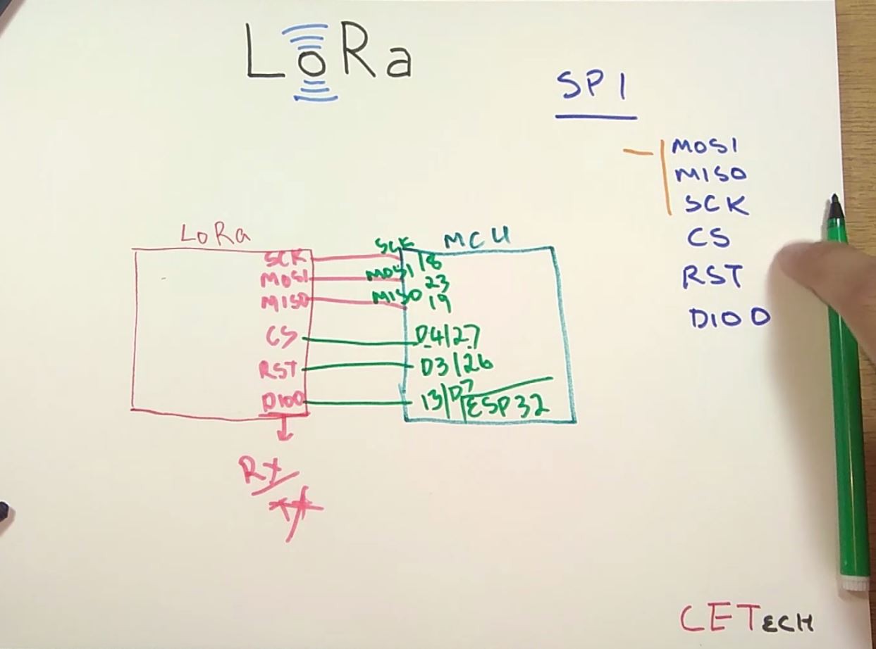
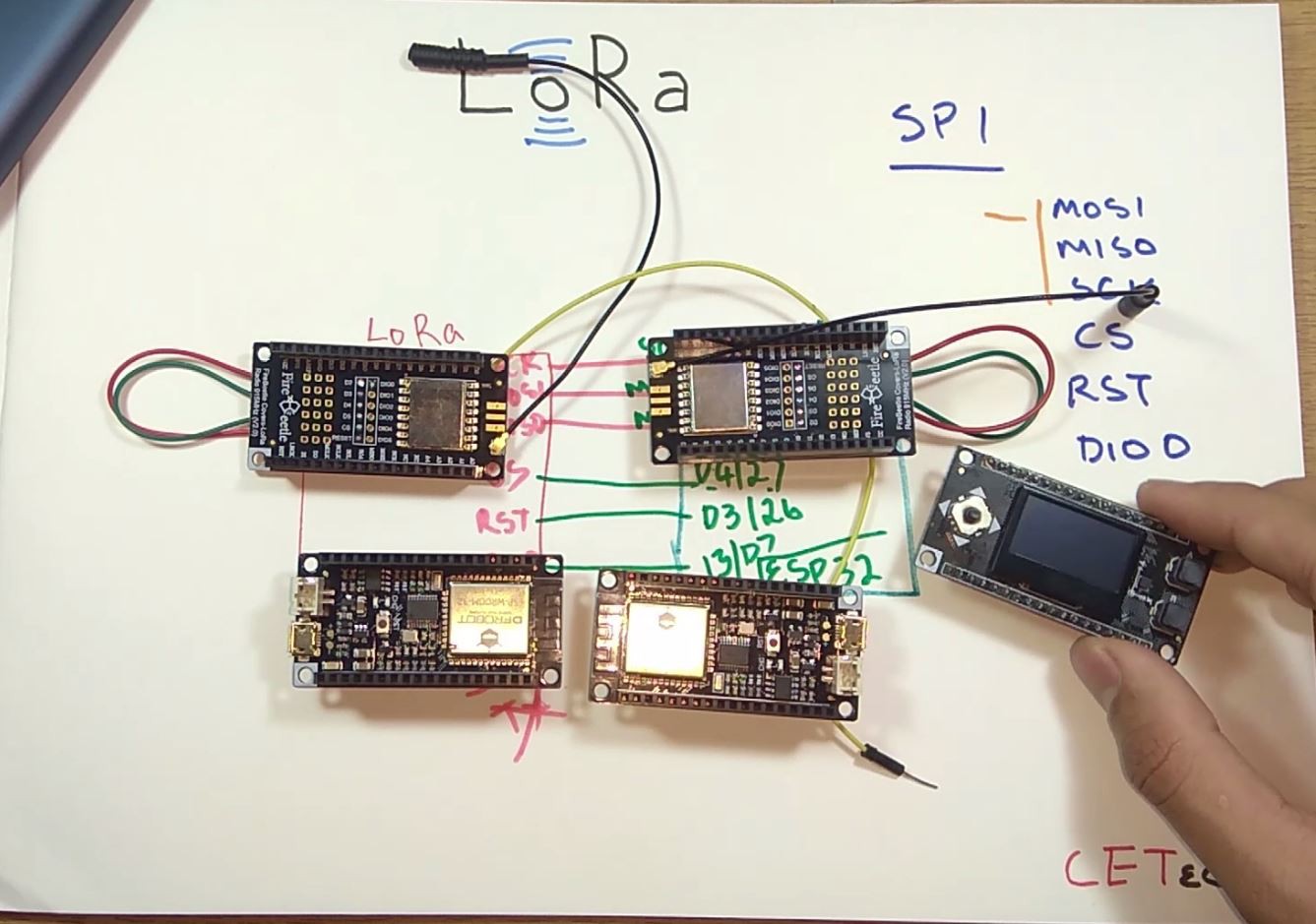
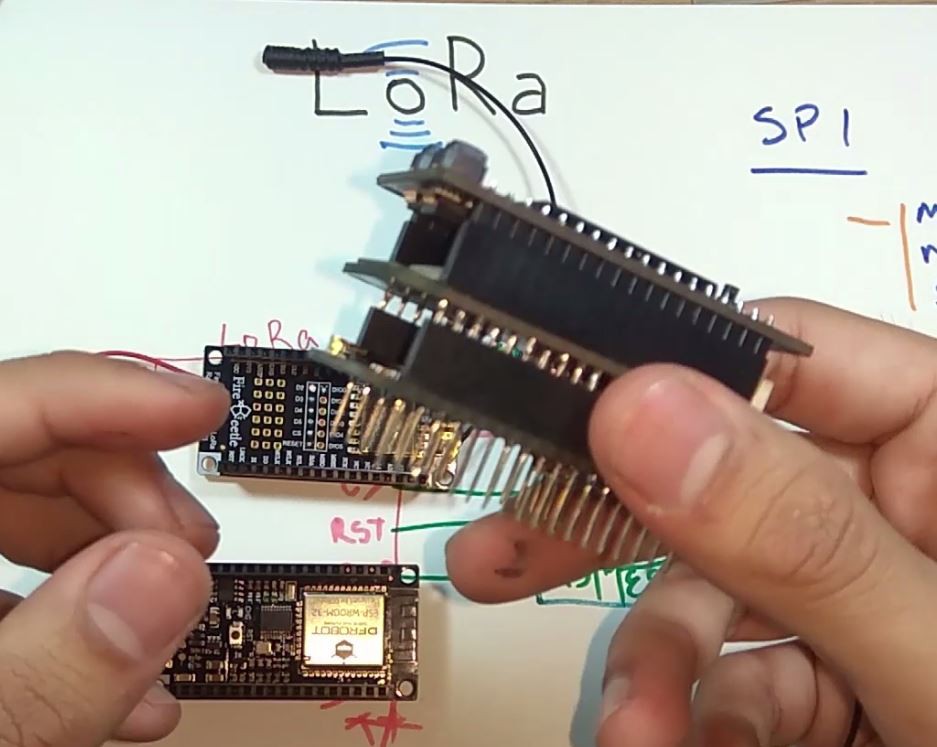
4Connections and soldering
1. Solder the modules with the stackable headers.
![]()
2. You will need to connect both the LoRa modules to the ESP32 modules according to the wiring diagram.
![]()
3. Gather all the 5-6 modules that you will be using and stack them according to your need of the Radio. For these steps I highly recommend watching my video as this part is explained in detail there.
![]()
![]()
-
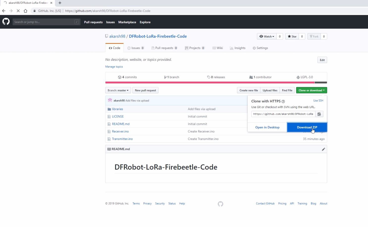
5Coding the module
1. Download the github repository: https://github.com/akarsh98/DFRobot-LoRa-Firebeetle-Code
![]()
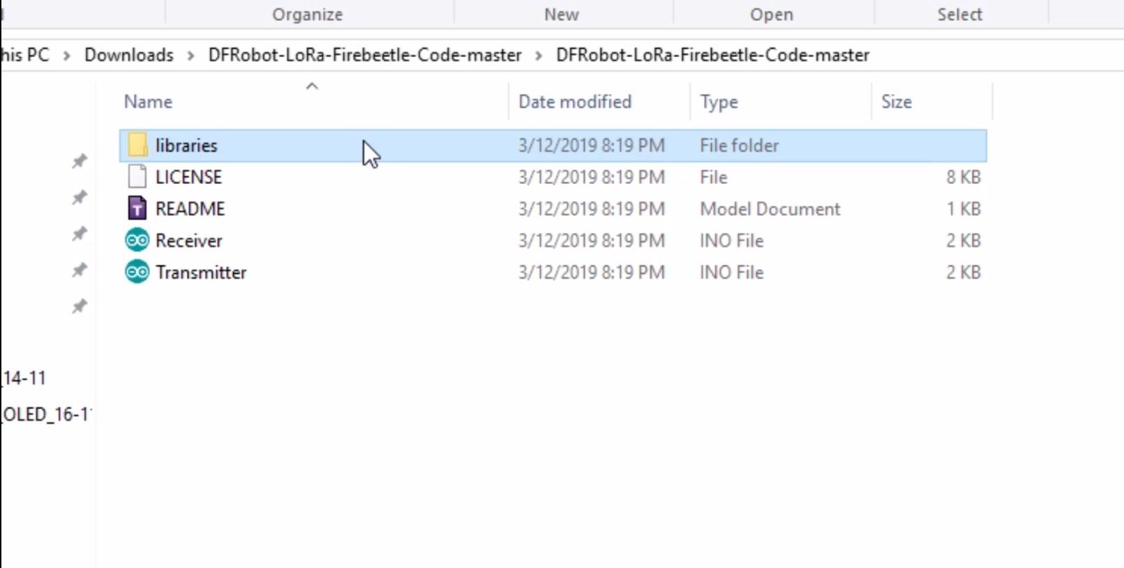
2. Extract the downloaded repository.
![]()
3. Copy the libraries from the downloaded repository to the Library folder in arduino sketch folder.
4. Open the Transmitter sketch in the Arduino IDE.
5. Navigate to Tools > Board. Select the appropriate board that you are using, Firebeetle ESP32 in my case.
![]()
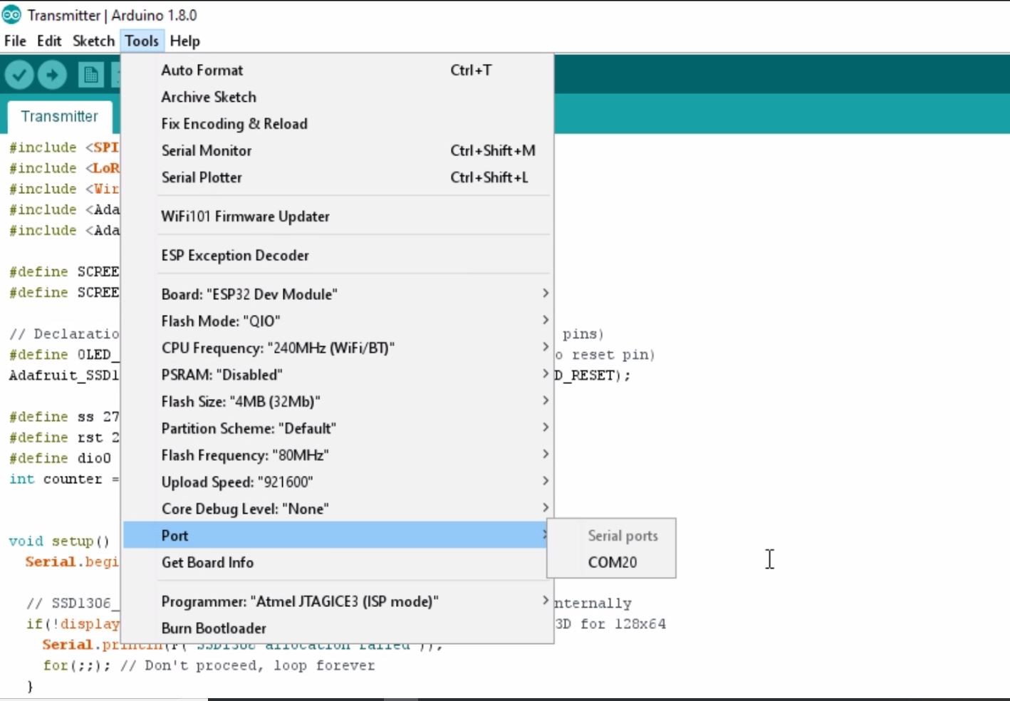
6. Select the correct comm. port by going to Tools > Port.
7. Hit the upload button.
8. When the tab says Done Uploading you should repeat the above steps with the receiver module to upload the code.
-
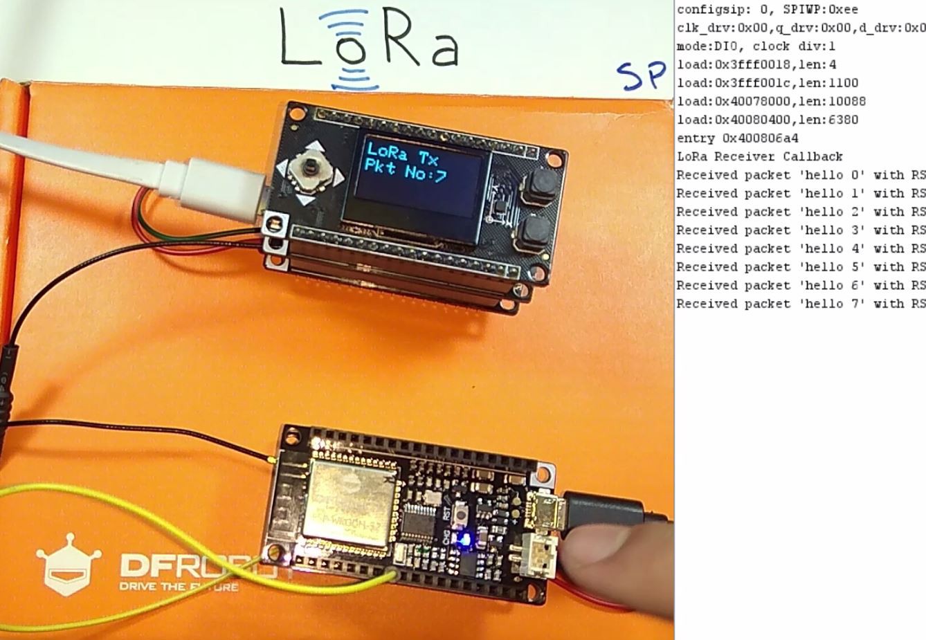
6Playing with the LoRa Radios
As soon as power is given to both the modules the OLED on the transmitter starts showing the packet number that is being sent, on the other hand the Serial monitor connected to the Receiver shows the received packet with the signal power
![]()
LoRa ESP32 Radios Easy getting started tutorial
Get started with LoRa Radios easily without ann much wiring. This is possible by using stackable modules from DFRobot.
Discussions
Become a Hackaday.io Member
Create an account to leave a comment. Already have an account? Log In.