 natalie
-
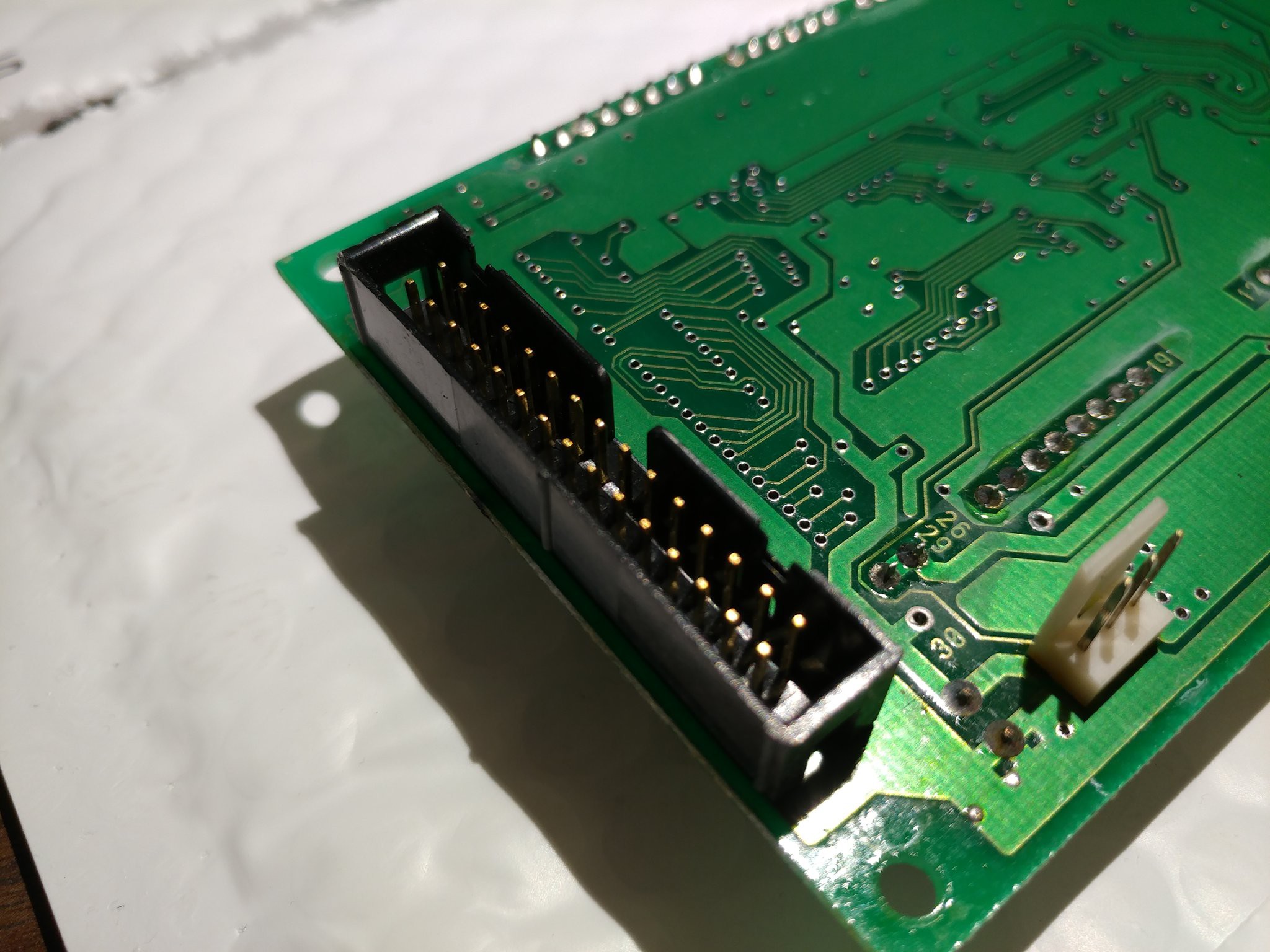
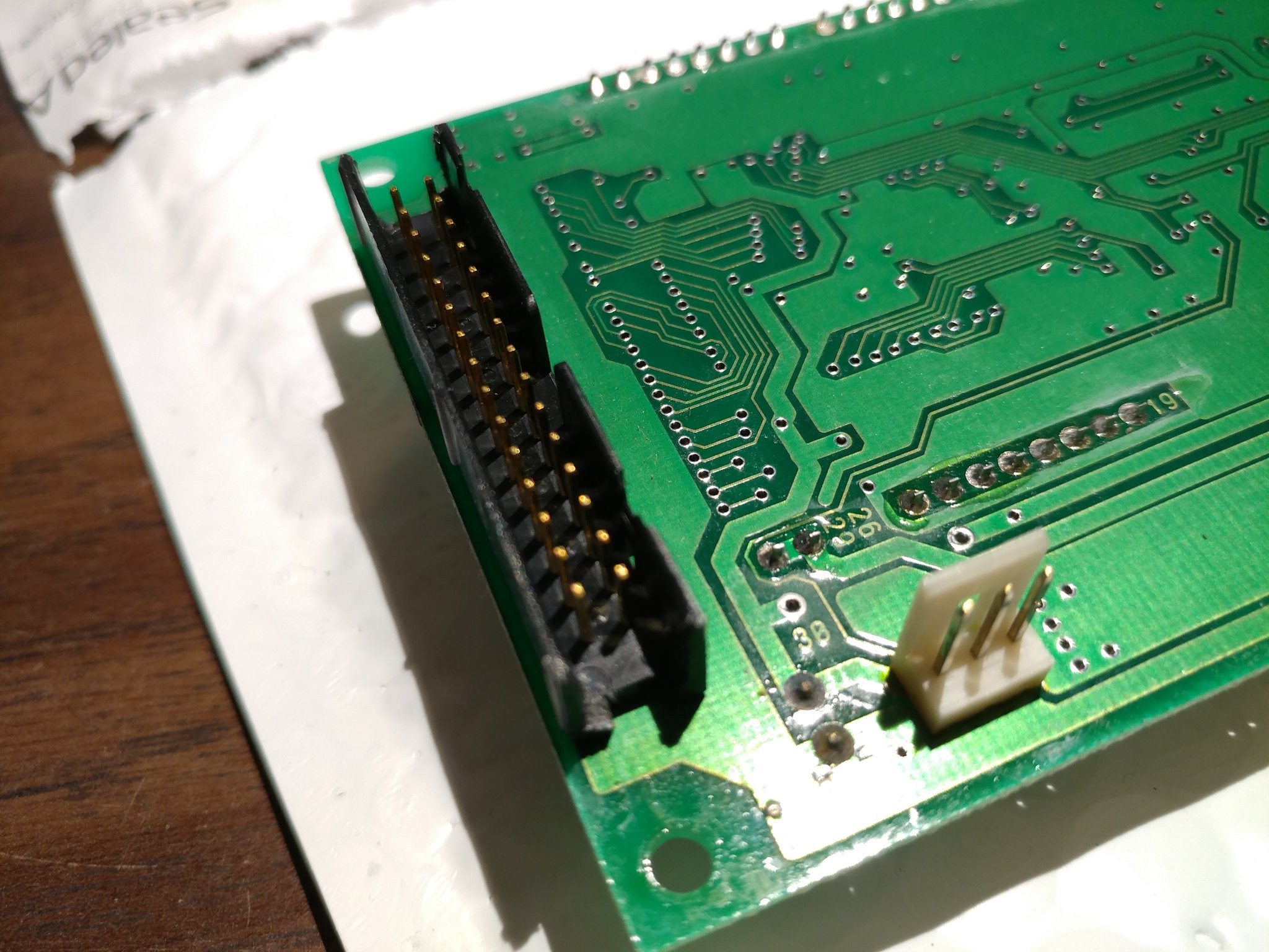
1Modify the VFD module's connector shell
The VFD module's connector is smaller than the pinheader on the Mega, and the plastic shell would prevent it from seating.
![]()
Carefully cut or file away the short sides of the connector shell as seen below. Be careful when doing so - the VFD has very fine construction inside and the physical shock from a pair of wire cutters could damage it.
![]()
-
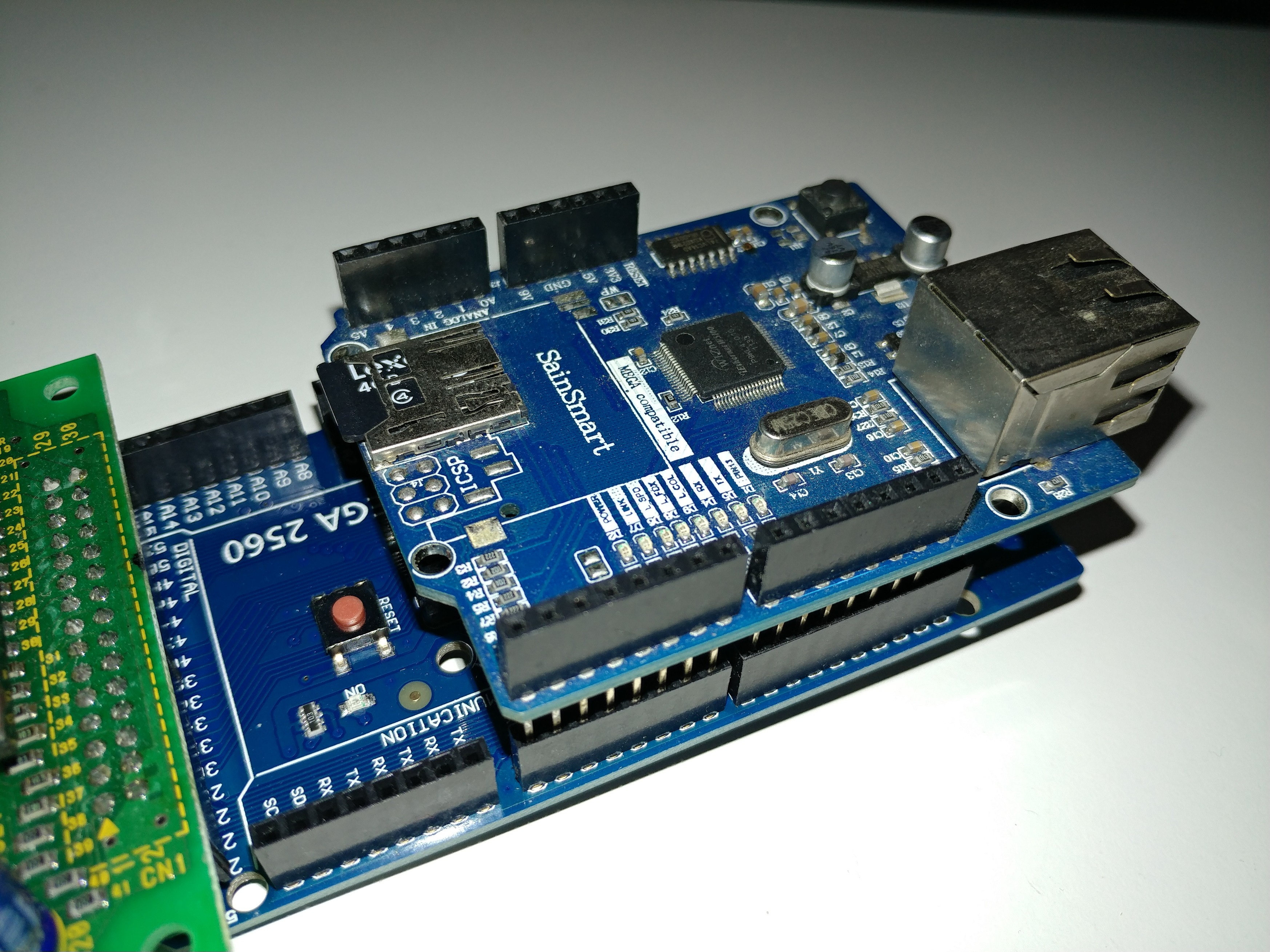
2Plug the module onto the Mega
Seat the module onto the Mega's large pinheader. Pin 1 on the module's connector should go to digital 23 on the Mega. Proper positioning is important and getting it wrong could result in a dead VFD, Mega, or PC.
![]()
-
3Connect an SD card
Connect an SD card to the Mega. I had an ethernet shield handy which happened to have an SD card slot on it, but any breakout should work fine.
![]()
-
4Connect power to the VFD
The VFD can be powered from the Mega or from an external source. If powering from the Mega you'll need 2 MtF jumper wires.
Note: The VFD is very power hungry and uses over 750mA at 5V. If powering through the Mega and the Mega is powered over USB, this will trip the Mega's polyfuse and cause the board to appear to be dead. If using an external power supply, the 5V regulator on the Mega will not be able to supply the required current. It's recommended to power the VFD module externally, but using an external 5V power supply on the Mega and connecting the VFD to the VIN line should also work. Greater than 5V input will damage the VFD module!
In my case, I simply bypassed the polyfuse on the Mega with a wire, and ensured I powered it from a source capable of at least an amp.
Power connector pinout:
- 5V
- Not connected
- Gnd
![]()
-
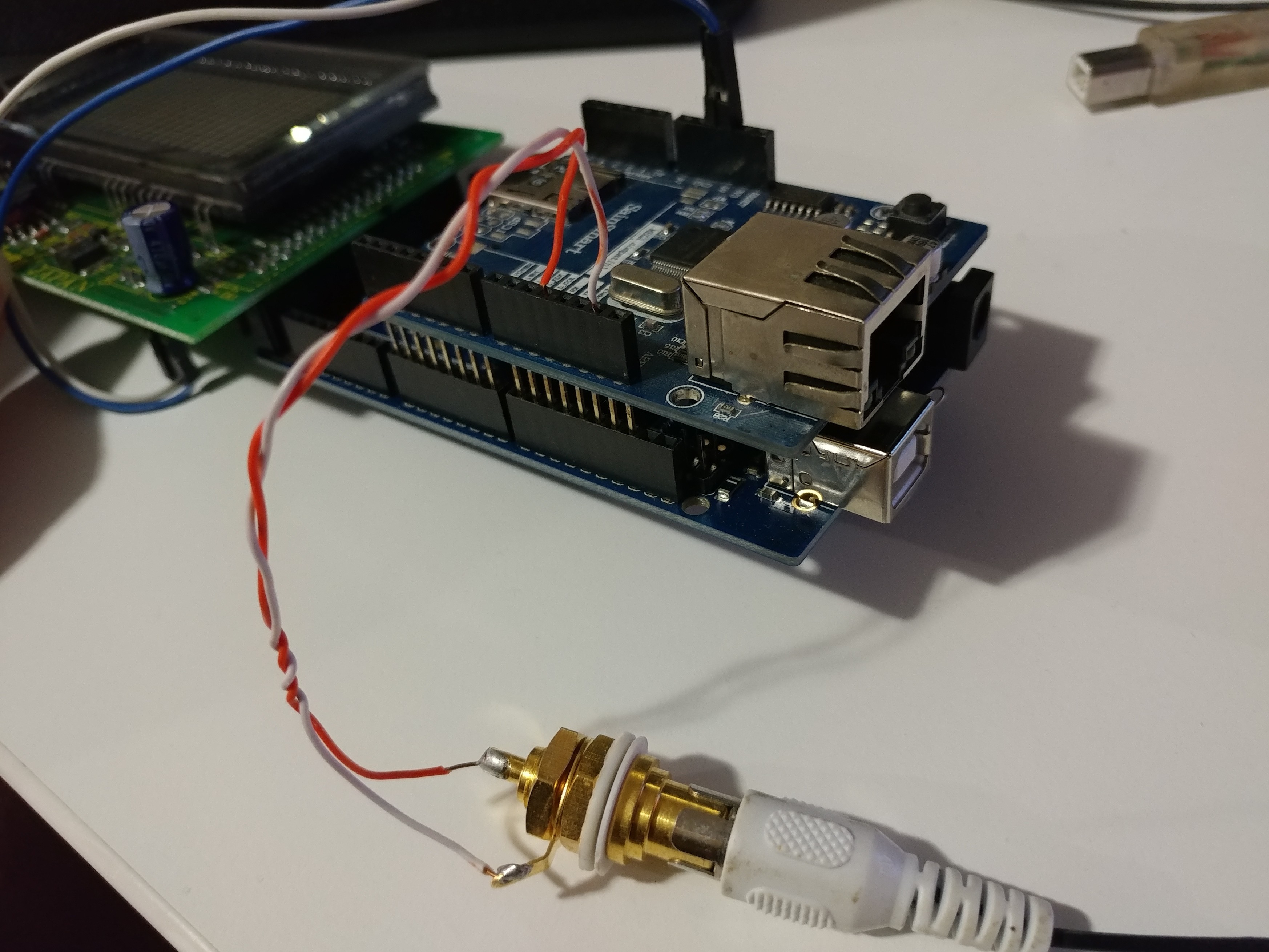
5Connect audio output
Audio output from the code is PWMed at 32 kHz and is available on digital pin 11. For quick testing it should be okay to connect directly to an amplified speaker. For long term use, it is highly recommended to use a low-pass filter to remove the PWM carrier frequency to avoid damage to speakers. You must use an amplified speaker - connecting a raw speaker directly to the Mega will damage it.
I made up a quick RCA-to-bare-wires breakout and then just stuck the wires in the pinheader.
![]()
-
6Flash the code
Obtain the latest source code from the Git repository and flash it to the Mega using the Arduino IDE. The reader is expected to be familiar with this process.
-
7Convert the video file and populate the SD card
The source video file must be split into separate video and audio files. These files are not included with the source code and must be generated yourself. Example instructions for conversion are available here.
Place the resulting files into the root of a FAT32-formatted SD card.
-
8Try it out!
If you made it this far, you should have a cute little Bad Apple!! player.
![]()
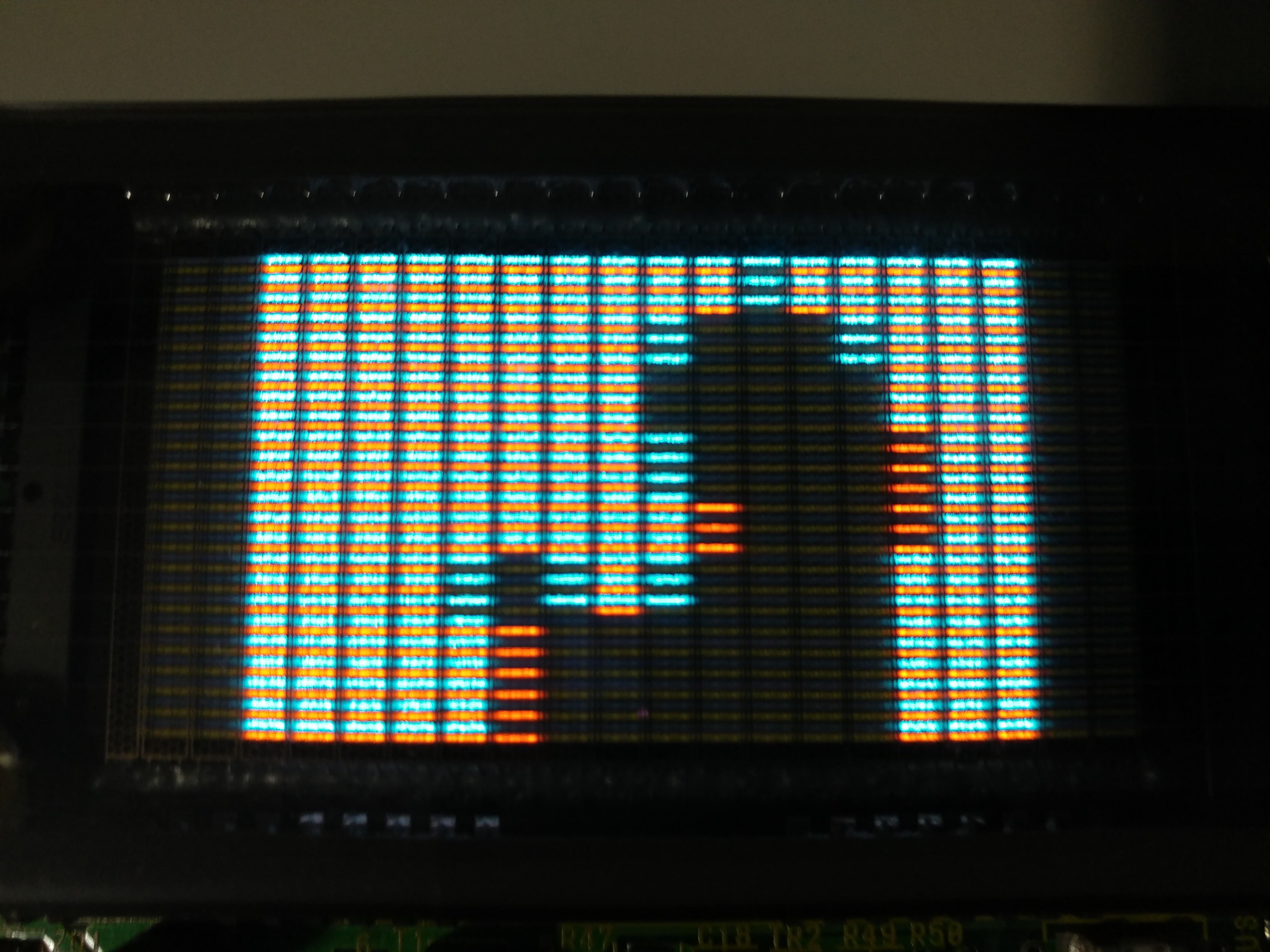
Bad Apple!! color VFD ver.
Bad Apple!! on the Noritake itron GU20X8-301 3-color VFD module


Discussions
Become a Hackaday.io Member
Create an account to leave a comment. Already have an account? Log In.
Hello, very nice. I also have a GU20x8. I am trying to find the library you use gu20x8_write. It is not in your repo. How would I get it? Any tips on what the big header pin outs affect. Couldn't find a manual for it online. okgr8thx
Are you sure? yes | no
All of the code is in badapple.ino, Gu20x8_Write is just a standalone function (although it does need the initial pin setup from lines 64..89).
Most if not all of the other pins are not connected to anything. I think the existing code already uses all pins that do anything. Shame, because I was hoping there would be a vsync signal exposed on the connector, but I couldn't find one...
Are you sure? yes | no