-
Motion Trajectory Smoothing with Ruckig
07/18/2022 at 01:38 • 0 comments![]()
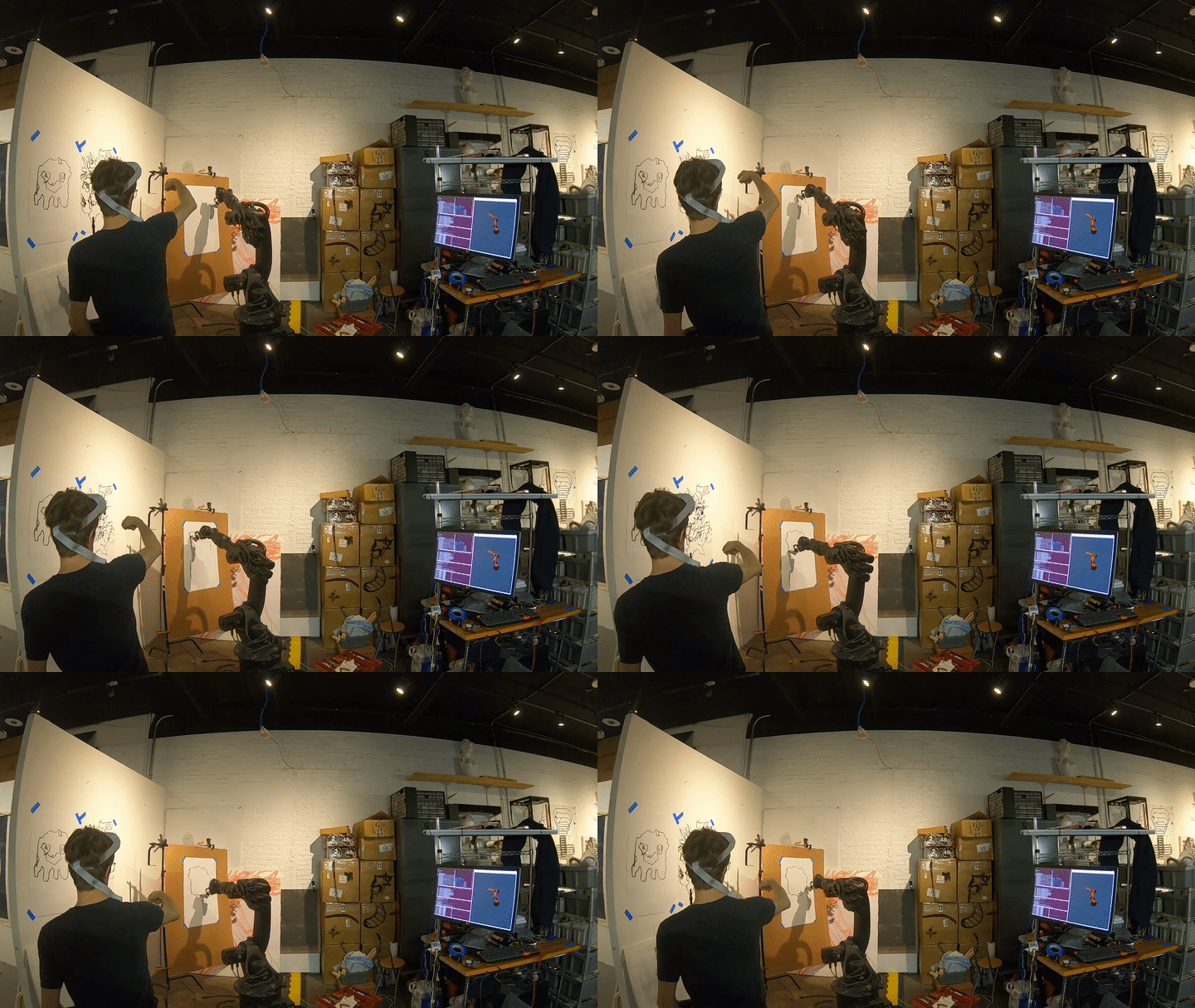
In the last post I showed how to set up CollisionIK for my Kuka KR 16 robot arm in ROS so that it can be used to solve the inverse kinematics (IK) problem in real-time while handling singularities, collisions, and other issues. I only showed it working in simulation because there were still some issues to overcome before it would be safe to use with the real robot. In this post I show my solutions to those issues and the resulting system being used to control the real 600 lb robot arm based on device and hand tracking data obtained using WebXR on a phone and Quest 2, respectively.
The motion from CollisionIK looked fairly reasonable in simulation, so why couldn’t it it just be plugged straight into the robot? The main reason is safety - nothing was in place to prevent dangerously fast or unexpected motion. In the worst case that motion could hurt someone, or it could damage the robot. In the best case it will cause the RSI interface on the robot controller to throw an error and do an emergency stop. So at the very least we need to constrain the motion sent to the robot just so it will keep doing what we tell it.
CollisionIK contains code to minimize the velocity and acceleration of the robot but nothing to limit those parameters to safe ranges. Due to the nature of the solver - it relaxes constraints to find solutions in situations where other solvers would give up and stop - it’s not really appropriate to implement safety constraints as goals in the CollisionIK objective function.
A Quick Note on Jerk
Another reason we can’t just proceed with the velocity & acceleration minimization included in CollisionIK is that we also need to limit jerk, which is the rate of change in acceleration. For small robots it’s sometimes ok to ignore jerk, but my KR 16 is big enough that ignoring jerk could lead to damage to the internal mechanisms of the robot.
You can get an intuitive sense of why by thinking about what acceleration means in the context of the robot arm’s drive mechanism. By Newton’s 2nd law, force equals mass times acceleration. The mass here is basically fixed. So whatever reasoning we do about acceleration also applies to force. Torque is the kind of force that’s relevant in the robot arm because it’s force applied to rotate an object (the arm’s joints). Now if we look at jerk again we can see that because it is the rate of change in acceleration it is proportional to the change in torque.
So if we have discontinuous jerk we have discontinuous torque. Physically a jump in jerk is like a whack to the input to the mechanism. A light mechanism has little inertia and will respond to the whack by accelerating all together. Like swinging a baseball bat into a baseball. A heavy mechanism with a lot of inertia will respond to the whack by shedding energy into breaking stuff. Like swinging a baseball bat into a brick wall. You might chip the bricks or break your wrists but you will not move the wall in time with the impact. If you keep pushing with all that force eventually the wall will yield, but only after a lot of damage has been done at the interface where the collision happened. This is how I think about what happens inside the robot to its gears when there’s discontinuous jerk.
Jerk-limited Motion with Ruckig
The goal is to limit the velocity, acceleration, and jerk of the motion of the individual joints of the robot arm. At the same time all of the individual joint trajectories need to be synchronized in time so that the tool at the end of the robot follows its target trajectory as close as possible. And these calculations need to be very fast so we can run them in real time, at minimum a few hundred times a second. Lastly, we need to be confident that we will always get a solution in a bounded amount of time. If even a single solution is late then the 12 ms RSI communication contract will be broken and the robot will stop.
Ruckig is a motion trajectory generation library that is a near ideal answer to these challenges. It can generate the jerk-limited motion trajectories we need in a matter of microseconds with guarantees about when we will get them. And it’s a relatively small open source library that is well written and easy to integrate. It has a corresponding paper that explains the theory behind how it works. Having used the Reflexxes library in the past for the same purpose I was blown away when I came across Ruckig. While Reflexxes was very impressive it accomplished less in an order of magnitude more code and was very hard to grok. It’s clear that Ruckig has a bright future ahead of it - it’s being used in the next version of CoppeliaSim and it’s already in MoveIt 2.
Ruckig + ROS Control
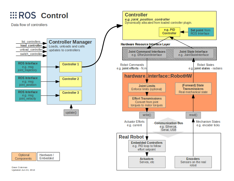
To plug Ruckig into Crash I’ve implemented a custom ROS controller that works similar to the Joint Trajectory Controller which is part of the default set of controllers provided with the ROS Control packages. ROS Control is how the low level hardware controllers for robots get integrated into an overall ROS system. It provides abstractions to implement the hardware controllers in a generic way so they can be commanded according to various standard interfaces. For example, in my case I want to provide target angles for the joints. But in another application you might want to provide target velocities instead.
![]()
(http://wiki.ros.org/ros_control)
ROS Control provides a framework for implementing the controllers and a system for loading and managing them at runtime. But the sophistication of what it provides creates a barrier to understanding. It took me a good amount of thrashing around before I understood what code I needed to write where to get what I wanted. And bad / sparse documentation caused me to waste a bunch of hours finding the right combination of esoteric runes to inscribe on my package to tell ROS Control to load my custom controller.
While figuring out how to please ROS Control was frustrating, the actual proof-of-concept controller is very simple. It mimics the interface from the Joint Trajectory Controller. It takes in Joint Trajectory messages and feeds their last joint pose into Ruckig as the motion target. Then in its update function Ruckig is invoked to generate the next incremental step towards the target and the joint angles returned by Ruckig are fed to the Kuka RSI Hardware Interface from the Kuka Experimental ROS Industrial package.
Eventually it would be cool to extend this to make a controller that fully works like the Joint Trajectory Controller but uses Ruckig under the hood to integrate new trajectories. I didn’t try to implement the partial trajectory replacement and future planning that that package does because I’m only interested in real time motion for now. I just replace the target with the latest and make no attempt to plan motion into the future. I’ll extend it if I need that but otherwise I welcome someone else to pick it up and run with it.
https://github.com/jmpinit/ruckig_control
Demos
For the following demos I used the WebXR web browser API to get 3D tracking data to stream into ROS as the target pose for CollisionIK. WebXR is still unstable and not available everywhere but it is becoming very viable for producing VR and AR applications on the web. I am planning to use it to build the control interface I want for the art-making workflow that is motivating the development of Crash.
I’ll share more of the details, including code, in a future project log. But basically what I did for these demos was modify the Immersive Web WebXR Samples to stream poses over a WebSocket to ROS. I have a basic HTTPS server in Python to serve the web pages, a WebSocket server, and a ROS node written in Python. Needing to get around the use of different Python versions (3 for the web stuff and 2 for the ROS stuff) I lazily bashed together ZMQ communication between the WebSocket server and the ROS node. So the data flowed like browser —WebSocket→ WebSocket server —ZMQ→ ROS Node → CollisionIK → Ruckig —RSI→ Robot.
Drawing with WebXR on a Phone
Drawing with a Finger using a Quest 2
Next Steps
Now that I have a viable real-time motion control system I’m going to move on to building a tool system that can support the larger art-making workflow that I have in mind. So far I’ve been focused on getting the robot to move, but now I’ll be building a system to let the robot see what it’s doing and adjust on the fly.
-
Real-time Motion Planning with CollisionIK
06/19/2022 at 00:03 • 0 commentsMotivation
One major barrier to a fluid creative workflow with robots is the often stilted sense-think-act loop. Every time through the loop the robot first gathers information about the environment, crunches the numbers to generate a plan, and then executes that plan. Without special care the individual steps can take significant time, which results in a robot that can’t fluidly adapt to changes in the environment or high level control inputs.
For my system the think step has been the bottleneck. Previously I demonstrated real-time communication with my Kuka KR 16 robot arm using a driver from ROS Industrial and motion planning with the MoveIt motion planning framework. Even though the underlying control data being sent to the robot was on a 12 ms time step the motion planning step in MoveIt often took a few seconds. And there was no straightforward way to append new plans found while moving, so the robot would come to a stop after finishing executing each one. Metaphorically, the robot was closing its eyes, covering its ears, and running through a room. Only when it finished running did it open its eyes to see whether it had made it to the other side or slammed into an obstacle; and uncover its ears to be told what it needed to do next.
If we had a system that kept its eyes open and ears uncovered while taking action we could change the kind of problems we can solve with it and the ways that we implement the solutions. We could:
- Have a human step in at a moment’s notice to move the robot out of a tight situation or give it hints about what to do. For example, we could use a VR controller to move the tool to the canvas. Or do computer mediated painting where input from a haptic controller is filtered, scaled, or otherwise modified before directly moving the tool on the end of the robot in real-time.
- Adjust motion in response to fast, unpredictable, and chaotic changes in the environment. Obstacles moving around, the work surface changing, or small details like paint drips.
- Use iterative algorithms to explore and manipulate the environment. For example, using a camera to visual servo towards a canvas. Often it's much easier to come up with a solution to a perception problem by thinking about taking small steps down a cost gradient.
To do these things we need real-time motion planning to go with our real-time trajectory execution. There are many kinds of planning problems in robotics but the one that I am mainly interested in here is about taking a path for the tool on the end of the robot through cartesian space (XYZ and rotation) and finding a corresponding path through joint space that has the tool follow the target path as closely as possible while avoiding problems like collisions and singularities. MoveIt provides several planners that can solve this particular problem in a global, offline way. That is, it will find a solution that is close to the “best” possible given the constraints, but it will calculate it all at once beforehand. What we want instead is a hybrid: local-first, global when feasible, and very online (real-time).
Survey of Solutions
BioIK
Back in 2019 I was looking at BioIK as a potential solution. It is robust because it continuously creates populations of potential solutions for what to do in the next moment and quickly scores them based on various criteria that are based on how well they meet the goals and avoid potential issues. This lets it be very flexible but also fast. Because there’s a whole population of potential solutions at each step you can tune its performance or characteristics by controlling the population. For example, if you want more speed you can reduce the population of potential solutions.
It seemed pretty great on paper, but in practice I’ve run into difficulty getting it to produce motion with the qualities I desire. It provides a myriad of different solvers that have different properties. The default one is global and not ideal for adapting to on-the-fly updates. Some of the other solvers are ok for that but come with other limitations.
When I found CollisionIK (described below) I grokked that much quicker and immediately had results I liked, so I set BioIK aside. Some day I hope I can finish exploring BioIK and either make my criticisms concrete or find the way to get it to do what I want.
V-Rep / CoppeliaSim
In the past I played a lot with V-Rep, which is now called CoppeliaSim. I wrote plugins for synchronizing the state of a UR5 or a KR 16 in V-Rep with a real robot and then developed many different experiments on top of that. Most were done during a short two week workshop that I ran at MIT:
And some were done at other times:
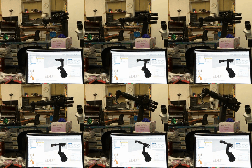
![]()
For IK I was using the built-in damped least squares (DLS) method provided by V-Rep (an overview of how that works can be found here). It was surprisingly stable in most cases. Though occasionally performance would drop and sometimes crazy solutions would be returned.
To a large extent I’m just trying to port the experience I had working in V-Rep over to ROS and build on it. V-Rep was great for rapid prototyping. I could quickly script new ideas in Lua, test them out in the sim, and then “flip a switch” and run them in real-time on the robots. By communicating via sockets with external programs (like Unity) we were able to build a lot of interesting dynamic tools and experiences quickly. But V-Rep / CoppeliaSim is not free and open and it was often frustrating not being able to reach in and see exactly what was going on or make changes. It was also not a great fit for collaborating with the rest of the robotics ecosystem, which is heavily oriented towards ROS-native systems.
MoveIt Servo
In the time since I stopped working on this project there have been a good number of new developments in motion planning in ROS. One of these is the moveit_servo package for MoveIt 2.
I have not evaluated it yet, but may in the future as part of a bigger effort to switch to ROS 2 and take advantage of the many improvements in MoveIt 2 (e.g. hybrid planning). One thing that gives me pause is that the package seems to have mostly just been tested on Universal Robots robot arms so far. I have the impression that it’s still early days for this package, but that it has potential and is worth mentioning even though I haven’t yet rigorously evaluated it.
CollisionIK
Now we get to the basket that my eggs are currently stored in.
I have been hearing about neural-network based approaches to motion planning for some time, and did a little reading on them. But I mostly saw research papers without practical, working open source code that I could immediately use. When I started working on this project again I decided to take a fresh look at what is out there. The one that stood out was CollisionIK (preceded by RelaxedIK) from researchers in the University of Wisconsin-Madison's Graphics Group.
The key idea is that you can come up with loss functions for the constraints you want the robot to obey, combine them into an objective function, and then train a neural network to approximate that objective function 2-3 order of magnitude faster than you can evaluate the original full objective function. By normalizing the relative importance of your constraints using a well-chosen parametric loss function you have control over which ones get relaxed first when a perfect solution can’t be found. In the context of this project that means we can tell the robot to give up on following the tool path closely if it needs to avoid a collision or a singularity, but in a way that smoothly scales based on the “severity” of the problem.
This ends up being a really great approach in practice. It’s relatively easy to nudge the planner to do what you want by adjusting the weights of the constraints or adding or removing them. In a sense you can take a hammer to the objective function and the neural network training process will smooth everything out and make it really fast. In practice I am able to eval the objective function at >3 KHz on the control PC in my studio. It’s not magic so there are still a lot of challenges hiding in the details, but speaking generally I’ve found that working with it feels a lot less like math and a lot more like painting.
On top of the nice approach there’s actual working code in a GitHub repo!
Setting it Up
Let’s get CollisionIK working in ROS. If you want to start out exactly like me then first follow this tutorial I wrote, “Containerizing ROS Melodic with LXD”. But using a non-containerized ROS Melodic installation will work fine too.
We are going to be focusing on getting the ROS1 wrapper for CollisionIK working. It’s essentially a three step process. Step 1 is to get the
devbranch of the original uwgraphics/relaxed_ik repo working, because that’s where the code for training the neural network resides. Step 2 is to get the ROS1 wrapper package built. Step 3 is to copy the configuration and NN weights trained in step 1 into the wrapper package so it can run and eval the objective function.Step 1: Training the Neural Network
We will install from my forked version of the relaxed_ik repo which fixes some small issues and is already set up for training the NN for my KR 16, the Waldo. You can see the specific changes I had to make in this commit on my fork. The summary is:
- Add a KR 16-2 URDF with the information about the robot.
- Create a “collision” file that contains:
- A description of the obstacles in the environment. At the moment I just create a box that represents the floor.
- Sample joint states that are not colliding for the NN training to start from.
- Edit src/start_here.py and fill in:
- URDF file name
- Name of the fixed frame (i.e. what is at the root of the kinematics chain in the URDF and bolted down in real life)
- Info file name, which will be generated later and loaded before NN training
- Joint names and their order, taken from the URDF
- The frame where the tool is attached
- The starting position of the robot. For the KR-16 this is a forward-facing, upside-down L with the tool plate “looking down”.
- The name of the collision file with
- Set the name of the info file in load_info_file.launch so it will be properly loaded before training later.
# Install system dependencies
apt update
apt install -y \
    build-essential \
    git \
    gfortran \
    python-pip \
    python-rosdep \
    liboctomap-dev \
    libfcl-dev \
    libopenblas-dev \
    ros-melodic-urdfdom-py \
    ros-melodic-kdl-parser-py \
    ros-melodic-kdl-conversions \
    ros-melodic-tf

# Install python dependencies
python -m pip install setuptools
python -m pip install --upgrade \
    readchar \
    python-fcl \
    scikit-learn \
    scipy \
    PyYaml \
    numpy

# Create our Catkin workspace if necessary and go there
mkdir -p $HOME/catkin_ws/src
cd $HOME/catkin_ws

# Clone the repo into the src subdirectory of our catkin workspace
git clone -b dev --depth 1 https://github.com/jmpinit/crash_relaxed_ik src/crash_relaxed_ik

# Grab package dependencies
rosdep init
rosdep update

# Build the package
catkin_make
At this point we are almost ready to train the neural network. But we need to fix one issue before that can happen. There is a shared library file at ./src/RelaxedIK/Utils/_transformations.so which I needed to recompile for my architecture. To do that we’ll download the library separately, build it, and then copy across the shared library file:
cd $HOME # Or wherever you want
git clone https://github.com/malcolmreynolds/transformations
cd transformations
python setup.py build_ext --inplace
cp ./transformations/_transformations.so $HOME/catkin_ws/src/crash_relaxed_ik/src/RelaxedIK/Utils/_transformations.so
Now we can train the NN, which takes about 10 minutes on my laptop:
cd $HOME/catkin_ws/devel
source setup.bash

roslaunch relaxed_ik generate_info_file.launch
roslaunch relaxed_ik load_info_file.launch

rosrun relaxed_ik generate_input_and_output_pairs.py
roslaunch relaxed_ik preprocessing_rust.launch
Once this is complete the configuration and NN weights are ready but we need to set up the ROS package before we can make use of them.
Step 2: Installing the ROS1 Package
cd $HOME/catkin_ws/src
git clone https://github.com/jmpinit/crash_relaxed_ik_ros1
cd crash_relaxed_ik_ros1
git submodule update --init

cd $HOME/catkin_ws

catkin_make

# Install an up-to-date rust toolchain
# I'm using:
# cargo 1.63.0-nightly (4d92f07f3 2022-06-09)
# rustc 1.63.0-nightly (cacc75c82 2022-06-16)
curl --proto '=https' --tlsv1.2 -sSf https://sh.rustup.rs | sh
# Make sure to add cargo to your PATH after installing

# I had to update my version of CMake to get the NLopt package to build
# I'm using cmake-3.24.0-rc1-linux-x86_64
# See <https://cmake.org/download/>

cd $HOME/catkin_ws/src/crash_relaxed_ik_ros1/relaxed_ik_core
cargo build
With some luck your build will succeed.
Step 3: Configure and Run
Copy the configuration files created during step 1 into the relaxed_ik_core submodule:
RIK_CONFIG=$HOME/catkin_ws/src/crash_relaxed_ik/src/RelaxedIK/Config

cd $HOME/catkin_ws/src/crash_relaxed_ik_ros1/relaxed_ik_core

cp $RIK_CONFIG/collision_nn_rust/kr16_2_nn config/collision_nn_rust
cp $RIK_CONFIG/collision_nn_rust/kr16_2_nn.yaml config/collision_nn_rust
cp $RIK_CONFIG/collision_nn_rust/kr16_2_nn_jointpoint config/collision_nn_rust
cp $RIK_CONFIG/collision_nn_rust/kr16_2_nn_jointpoint.yaml config/collision_nn_rust

cp $RIK_CONFIG/info_files/kr16_2_info.yaml config/info_files
cp $RIK_CONFIG/joint_state_define_functions/kr16_2_joint_state_define config/joint_state_define_functions
We also need to install my waldo_description package that has the meshes for the KR 16:
cd $HOME/catkin_ws/src
git clone https://github.com/jmpinit/waldo_description
cd $HOME/catkin_ws
catkin_make
Now we can finally run it!
# Run these in separate terminals
roslaunch relaxed_ik_ros1 rviz_viewer.launch
roslaunch relaxed_ik_ros1 relaxed_ik_rust.launch
rosparam set /simulation_time go
rosrun relaxed_ik_ros1 keyboard_ikgoal_driver.py
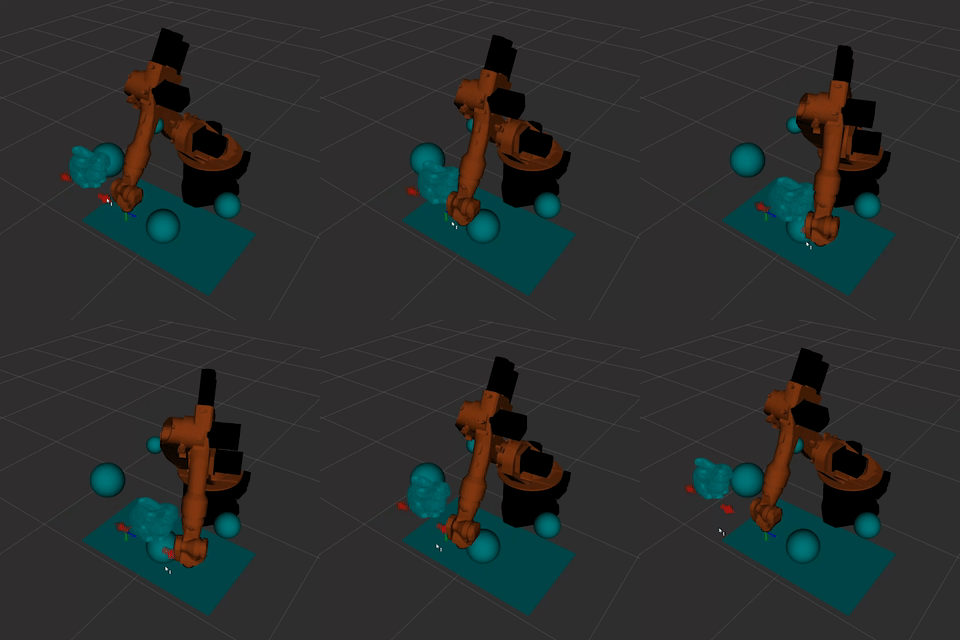
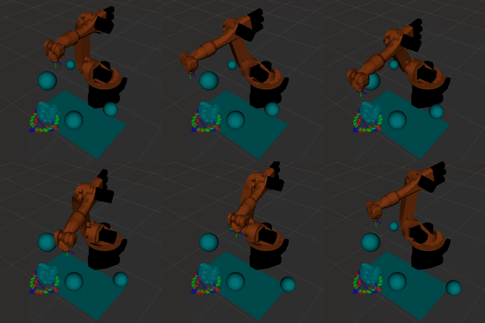
Here I’m moving a bunny 3D model back and forth in RViz while the robot tries to reach a fixed goal pose. You can see it smoothly move out of the way of the bunny (relaxing the position constraint) and then smoothly move back when the obstacle is removed.
![]()
Experiments
The code for these experiments can be found in the repo here: jmpinit/crash_blog.
For all of these I am just posting target poses to the /relaxed_ik/ee_pose_goals topic.
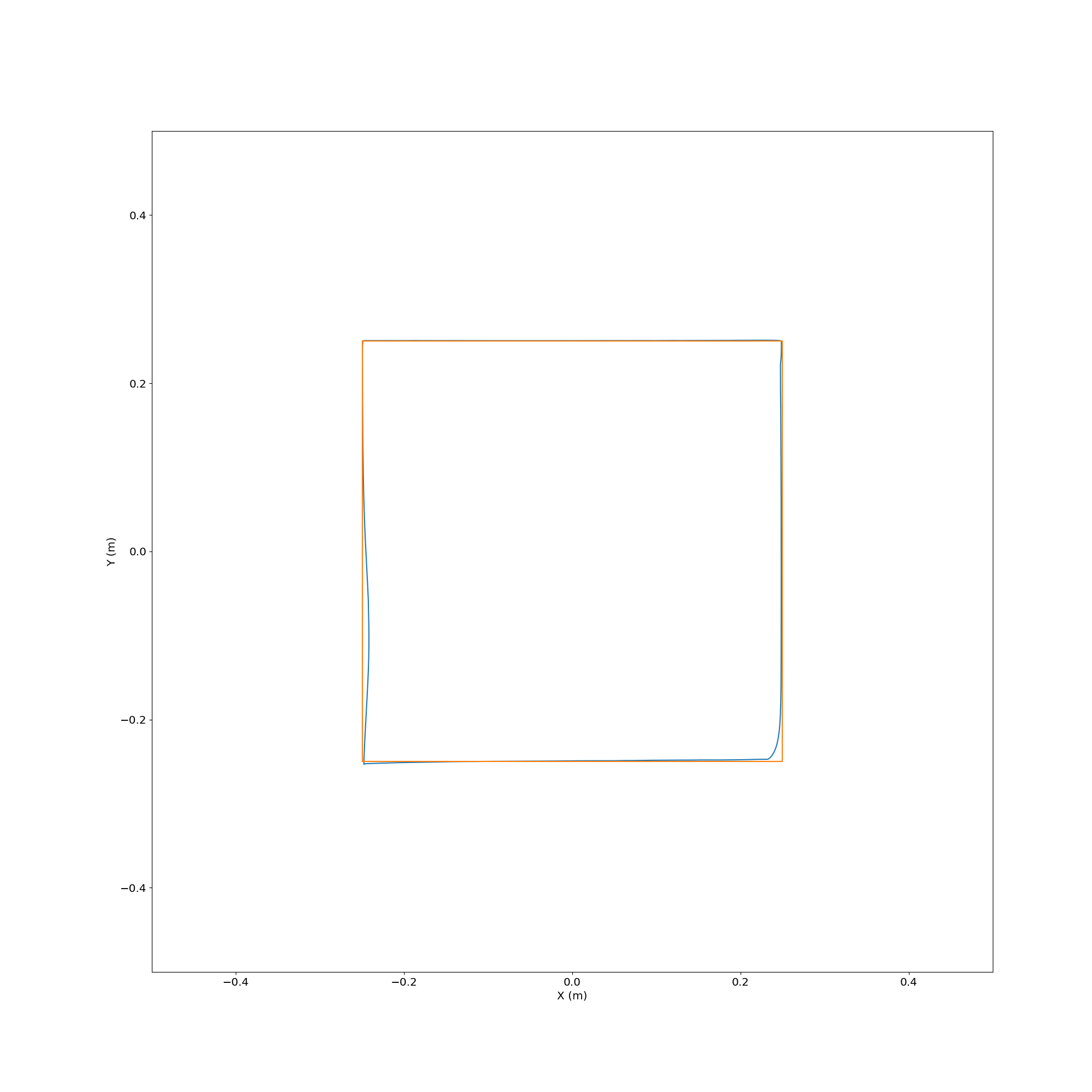
Following a Square
![]()
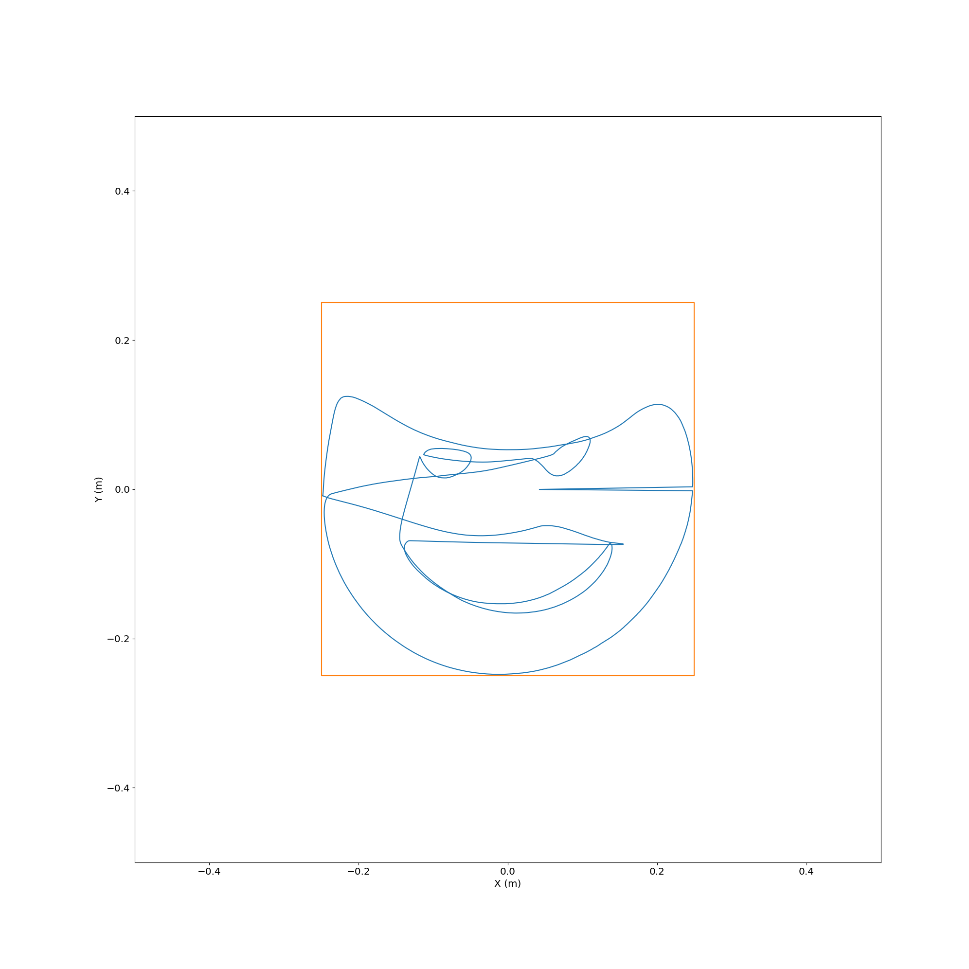
Here’s what the actual path looked like relative to the target from above:
![]()
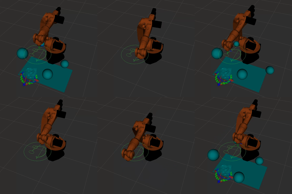
Plotting an SVG
![]()
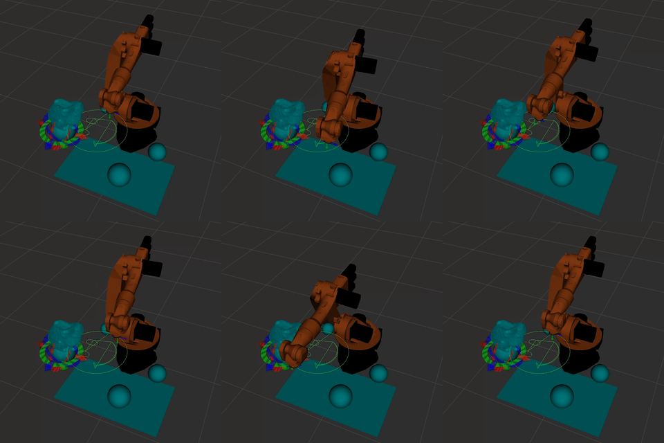
Plotting an SVG with a Bunny in the Way
![]()
Here’s what the actual path looked like relative to the target from above:
![]()
Future Work
Now I have a proof-of-concept setup with my robot of a flexible online IK solver. But you’ll notice that I didn’t include any demonstrations of this with the real robot arm. That’s not just because I ran out of time. There are some issues that must be addressed before this can be connected to the real bot.
Mostly CollisionIK does the right thing. But sometimes it does “glitch” and tell the robot to go as fast as it can after a point that is far away from where it is at and where it should be. For the real robot that could be extremely dangerous, or at the very least impractical. The real robot has speed and torque limits. RSI, which I use for real-time trajectory execution on my bot, will die whenever those limits are exceeded.
Additionally, even though it looks like it was intended for the CollisionIK implementation to have velocity limits, as far as I can tell those are not yet implemented. It tries to minimize velocity, acceleration, and jerk by setting minimization of those properties as objectives but without hard limits there’s always going to be the possibility of motion that is too aggressive.
We need to implement hard limits on these motion properties outside of CollisionIK. Ideally it would be done at the point just before the RSI interface on the ROS side of the system, because that will reduce the chance that some other node we add in the future unexpectedly sends unsafe motion directly to the bot. And the implementation needs to be fast, because these limits need to be enforced on every RSI update, which can happen up to 83 times per second (12 ms update cycle).
Making the challenge harder, instead of just failing when motion is attempted out of our desired parameter bounds we want to try to smooth it out. Often when prototyping we can accidentally generate fast transient glitches but still have overall motion that accomplishes our goals. If we could filter out the glitches and always have smooth motion while still being able to completely stop if motion stays out of bounds too long then we will have a practical system that can still ensure some degree of safety.
Next time we will look at how to use the very impressive Ruckig motion trajectory generation library for motion smoothing and limiting. And finally get to take a look at some motion on the real robot.
-
Order (Robots) and Chaos (Paint)
06/18/2022 at 23:42 • 2 commentsIt’s been more than 3 years since I’ve updated this project. A lot of that time was spent on other work, but this project has consistently stayed on my mind. Now I’m coming back to it with a fat stack of notebooks full of ideas and a clarified sense of why this is worth pursuing.
What is the relevance of robots to painting? Here, combining the two is about creating an excuse to use a visceral, emotional medium to find and express ideas that capture something of the truths encoded in the boundary between ordered systems and chaotic ones.
I’m obsessed with the apparent paradox that great complexity can “grow” out of near uniformity evolving according to relatively simple rules. I wonder what limits of understanding may exist for agents, like us, embedded in the systems they are observing. I worry that I don’t have the right tools to identify, understand, or communicate the insights that might come from pondering these apparent paradoxes. I’m not going to make any scientific discoveries or write down any mathematical proofs about them. But I can at least make progress on them in a way that is personally meaningful to me.
That’s where this work comes in. I aim to use painting as a petri dish of chaos that happens to grow artifacts that can be meaningful to me and potentially carry some meaning to others. I’m building my own kinds of instruments for probing it that are biased by my interests in complexity theory and beyond. Robotics is just my chosen means for putting the instances of order and chaos that I’m excited by in close contact, and a platform for building tools to guide, capture, and communicate the activity that results.
-
Real-time Control with ROS
03/31/2019 at 04:13 • 3 commentsReal-time feedback is an important ingredient in tool embodiment. That is, when a tool reacts fluidly to human intention and the result of its action is available immediately and continuously it can feel like an extension of the body of the user. Like riding a bike, writing with a pen, or making music on a piano. After learning little attention needs to be paid to moving the right way and so the conscious mind can occupy the abstract space of the task the tool provides leverage over.
Industrial robots are not usually built with real-time feedback in mind, because most often they repeat the same basic motions over and over again in a static environment. And real-time control can be extremely dangerous, because a bug in the software regulating the motion can lead to unexpected motion of the robot. The only control usually exposed to a human user is the ability to start or stop the activity of the machine, or change its speed. The first significant technical hurdle of this project lies in figuring out how to overcome the base limits of the controller to enable real-time control over every joint in the robot.
Remote Control with KUKAVARPROXY
The KRL programming language environment on the KUKA Robot Controller v2 (KRC2) used in this project provides programming primitives for controlling and triggering action based on basic industrial I/O, but its a pain to set up such I/O and the control frequency is very poor (roughly a few Hz). It's meant mainly for switching on equipment like welders or reading inputs like proximity switches, not low latency communication.
Ideally the robot could be controlled over Ethernet from a regular PC. A common tool for doing that with older KUKA industrial robots is a third-party tool called KUKAVARPROXY. This tool runs under Windows 95 on the KRC and sets up a server that allows global variables to be read and written over a network connection via a simple protocol. A script written in KUKA Robot Language (KRL) running on the robot can read and set global variables to communicate with external client PCs.
There is some support for this mode of control in commercial software, such as the excellent RoboDK. By running a specified KRL script on the robot RoboDK is able to connect and read the state of the robot's joints and execute basic motion commands. RoboDK has a Python API that allows mediated control of the robot. In the video above a Processing sketch is used to generate simple motion commands that are sent to a Python server (code here) which calls the RoboDK API to communicate with KUKAVARPROXY on the robot and consequently the running KRL script. For setting up jobs in RoboDK this sort of functionality is sufficient, but it does not provide an avenue to the real-time control that I'm after. There is a critical flaw with this mode of communication which has to do with how the robot does motion planning during KRL execution.
To be able to plan motion properly KRL scripts are executed from two places at once. There is the normal "program counter" which is tied to the currently running command. But there is lookahead functionality as well, which executes commands into the future to fill the motion planner's buffer. Executing motion that depends on variables which can be changed at any time throws a wrench into this lookahead mechanism. Disabling lookahead means that the robot will come to a stop after every single motion command, making it impossible to build up fluid motion from the available motion primitives in KRL like lines and arcs.
I spent a while investigating KUKAVARPROXY and KRL before ruling them out. One of the products of that work was a rudimentary transpiler from Clojure to KRL. You can find an example of that tool used to implement a KUKAVARPROXY remote control script on GitHub here.
Real-time Control with RSI
If KRL is fundamentally limited when it comes to real-time control because of the lookahead feature, what are other options? What's needed is an interface at a level lower than KRL, ideally directly into the motion control system that runs in VxWorks on the KRC (Windows 95 is actually a subtask managed by VxWorks). The KUKA Robot Sensor Interface (RSI) is exactly that interface.
RSI is a package which was primarily developed to enable robots to be used in applications where their motion needs to be adjusted in real-time for fabrication tasks. For example, when using a robot for polishing it's necessary to modulate the pressure the robot is applying to the material being worked to get an even finish. Or when doing CNC milling it can be beneficial to reduce the feed rate if the tool is experiencing too much strain. For these types of applications it's essential that corrections can be applied to the motion with minimal latency and at a high control frequency.
To achieve the needed level of control RSI taps directly into the motion control system running in the real-time operating system of the robot controller. A special Ethernet card has to be installed on the control PC in the KRC which is mapped directly into a memory space accessible from the control subsystem running in VxWorks. The motion controller executes one interpolation cycle every 6 milliseconds, so that is the smallest unit of time relevant in RSI. An external system must receive and respond to RSI communications either every 6 ms or every 12 ms, depending on the mode. If at any point this time contract is violated then an emergency stop is executed, the robot comes to a halt, and execution must be manually resumed.
Enabling RSI on the KRC2 used in this project was an entire adventure on its own. Maybe I'll get into what that took in a future update. But what's relevant here is that it works, and it provides the sought-after mechanism for real-time control of the robot.
I started by implementing the RSI communications protocol (XML-based) in a simple server written in C++. One thread handled receiving and delivering the RSI packets on time, another ran a server to accept motion targets from clients, and another interpolated the motion to derive the correction for RSI to consume every 12 ms. Then my brother wrote an ARCore-based app to control the robot based on the movement of an Android phone:
The robot is shaky because | didn't bother to tune my motion controller. I used the excellent Reflexxes online motion trajectory library to handle making velocity and acceleration nice and smooth for the robot, but ended up with some oscillation in the target by not filtering the feedback RSI was providing from the robot. Still, I was happy with it as a proof of concept.
Introducing ROS
With the basic pieces of the system up and running, and after a lot of intervening events (moving the robot to a studio in the Brooklyn Navy Yard, installing industrial power, bolting it to the floor, etc.), I went looking for a platform to build the higher level functionality of the system on top of. Very quickly I came to the conclusion that the Robot Operating System (ROS) was the right choice.
ROS essentially defines rules for how the pieces of a robot control system are configured, started, communicate, packaged, etc. It's not exactly an operating system in the usual sense of that term - it is made up of software installed on top of a conventional operating system like Linux.
ROS specifies what "things" are on a robot's internal network and how those things find and talk to one-another. "Things" on this network are referred to as nodes. Right now some of the nodes in the ROS configuration for this project include a motion planner node, a motion controller node, and an application node. These nodes find each other thanks to a master node, called the ROS Master. They all know how to find the master and when they start up they tell the master how they can be talked to. Then later when other nodes want to connect they can just ask the master who there is to talk to, and then set up a direct connection to the nodes they want to chat with.
Communication happens via "topics". For example, there is a joint_states topic which is "published to" by a special controller node that can read the current joint angles out of the low level robot driver. Any node that wants to know the current joint angles of the robot, like the motion planner node, can "subscribe" to the joint_states topic. Every time there is a new update about the joint states every joint_states subscriber gets it.
So to get everything going you launch a bunch of nodes (each a process managed by the machine's OS) which are configured to connect to one-another in a specific way that accomplishes your goal. They all talk to the Master in order to find each other. Then they start publishing, consuming, and processing messages to accomplish the robot control task.
![]()
I created a set of ROS packages to setup control of the KR 16 via RSI. At the bottom of the stack is existing work done as part of the ROS Industrial project, which implements a driver for talking to the robot via RSI. Above that are some nodes from ROS Control, which handle management of the motion targets for the individual joints. Just below the top is the MoveIt motion planning framework, which figures out how the joints need to move over time to hit specified motion targets in a given coordinate space. I have it configured to use Bio IK for solving the inverse kinematics problem of the arm (what joint angles put the tool on the robot at a target position and orientation). Bio IK has nice properties in the context of real-time control, like fast execution time, graceful failure, and robust performance scaling.
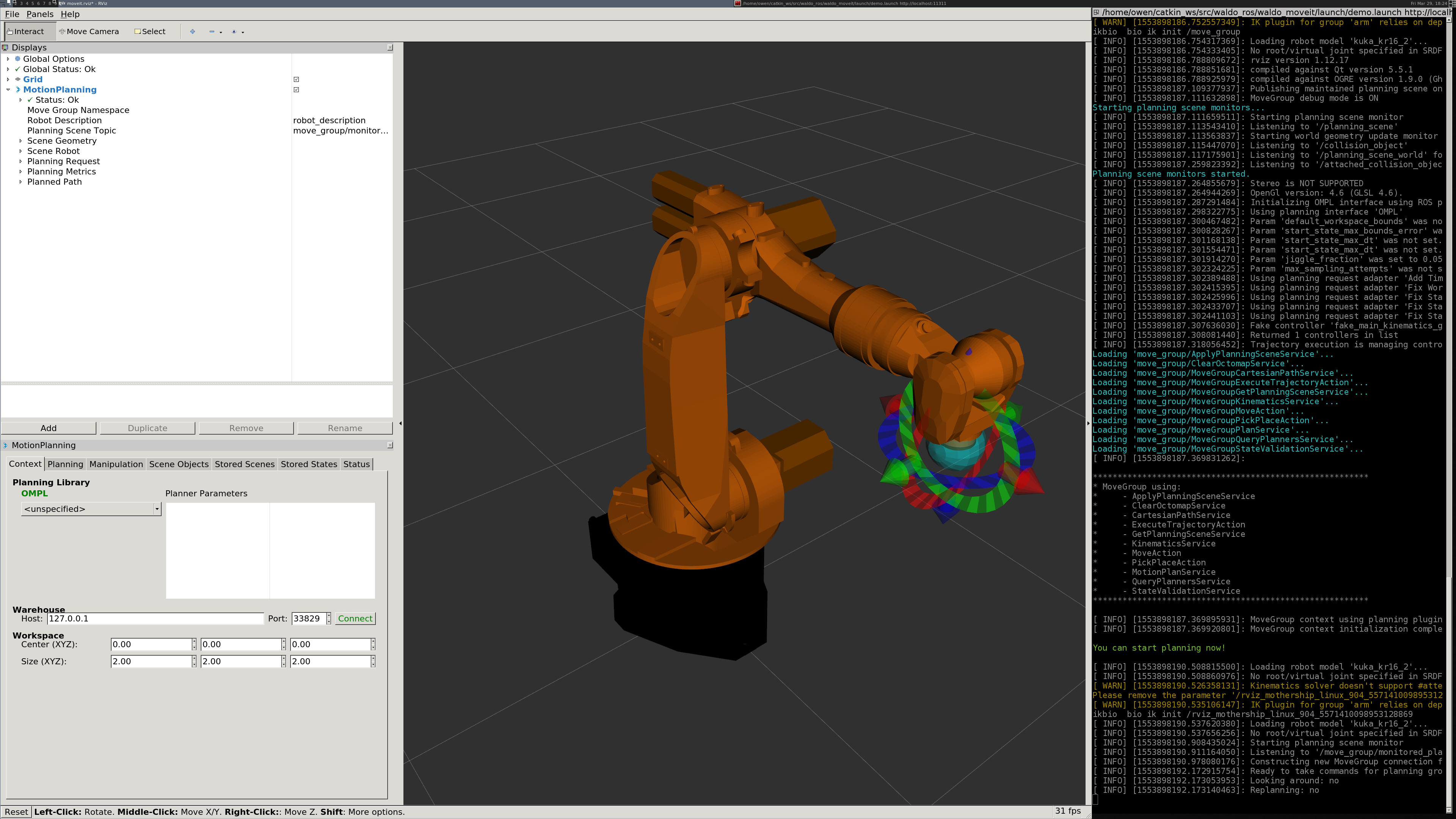
Right now RViz with the MoveIt MotionPlanning plugin provides the GUI (see image above). That allows for rudimentary control of motion targets, motion planning, and execution. The system can be launched in a simulation mode to test execution without the real robot connected.
The last piece of the current progress is a Python script node which invokes the MoveIt API to paint SVG images (see video at top of post).
An obvious limitation of the current demo is that it doesn't actually involve any real-time feedback and decision-making. The motion might as well be fully preplanned, because all the constraints are known in advance. However, the underlying system is, in fact, real-time. The next update will explore what it takes to punch through MoveIt to influence the motion as it is executed moment-to-moment.
Crash
A real-time creative coding environment for robot arms. For painting, performance, and other kinds of art.
 Owen Trueblood