Chris
Chris-
DIY Paper Thin and Flexible Circuits!
04/27/2019 at 18:08 • 2 commentsI don't mean to disappoint anyone, but I still have not managed to blind myself. Sorry.
As a bit of a refresher: to date I have taken two different approaches to trying to make this badass glowing eyeball. Both of which have had their pros and cons
- The custom made flexible PCB from Oshpark
- Professionally made and looks pretty
- Tough enough to handle the heat of a soldering iron
- Not flexible enough
- Hurts my eyeball
- The "circuit sculpture" of wires and LEDs
- Very flexible
- Much thinner
- Incredibly Fragile
- Quickly bends into a potato-shaped mess.
What I really needed was a happy medium between the two. Something that was much thinner and more flexible than the PCB, but also something that wouldn't take me hours to hand solder, and then be ruined at the slightest of man handling. Even more so, a process that was repeatable and easy enough for the home gamer would be ideal. I thought about various approaches for quite a while (nearly a month according to HaD), and I think I finally found the secret ingredient - copper tape! It's flexible, super duper thin, and can be applied to pretty much any substrate of your choosing.
What I find interesting is that copper tape doesn't exactly seem entirely commonplace, at least to me. I first encountered it in an arts-and-crafts-and-circuits type kit that my little brother got for Christmas. When I asked the nice man at the hardware store if they had any, he gave me a funny look. Apparently it can be used as some magic barrier against slugs and snails? The adhesive is also conductive, so maybe consider adding it as another tool in the toolbox.
With a little be of trial and error, and my secret ingredient, I think I have finally found a process for making super thin circuits, that hopefully some of you may also find useful.
Anyway. Let me show you how to turn some paper and copper taper into a circuit board that sits on your eyeball.
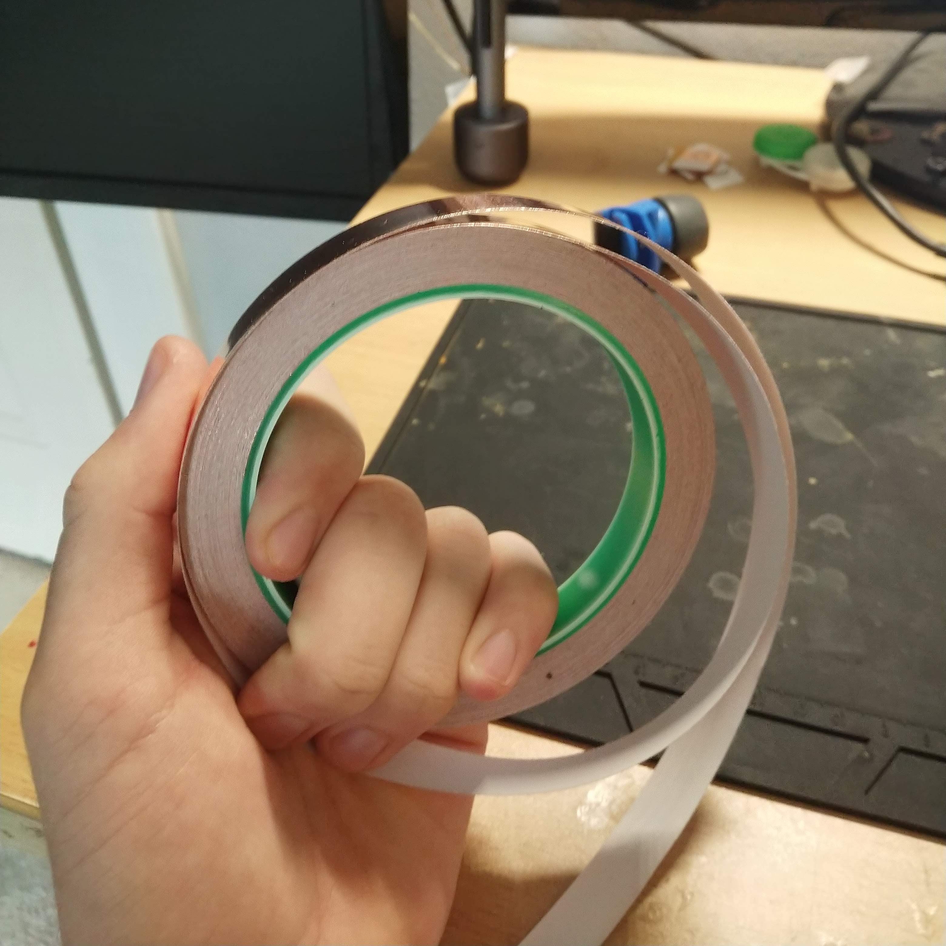
Obviously, the first thing that to do is get yourself some copper tape. It seems to be most commonly available in 1/4" and 1/2" flavors. I used 1/2".
![]()
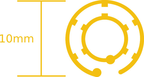
After that I needed to actually design the circuit board. For my very first prototype (the board made by OSHPark), I used plain 'ol Eagle. However, as some of you may know, Eagle tends to be a little less than user friendly when it comes to curved shapes. So this time around I opted to use Inkscape. The program is commonly used by hackers to generate vector files for laser cutting and the like. I whipped up the board in a fraction of the time it would have taken me to do it in Eagle. It looks like this:![]()
The whole thing was about 10mm^2. The little round bits nubs towards the bottom are where I soldered the leads wires, and each of the radial tabs are size 0603(1608) SMD pads. The plan here is that the soldered LEDs connect the inner ring to the outer ring, that way I don't have to worry about getting rid of any extra support connections later.
From there I then copy and pasted my design a whole bunch of times and printed out a test page to give myself a template as to where to put the copper tape on the paper.
![]()
After putting down the copper tape in the right place, it's just a matter of running the paper through the printer again!
![]()
As you can see below, the designs on the left and the right didn't print very well. By laying down strips of copper tape and printing a whole bunch of designs at once , there is a much higher chance that I will get some userable designs.
![]()
Fortunately, if you don't feel like cutting and laying down a whole bunch more copper tape a little bit of acetone wipes the ink right off and you can reuse the same paper!![]()
I cut them into bite size little pieces!
![]()
Then a quick bath in some Ferric Chloride
![]()
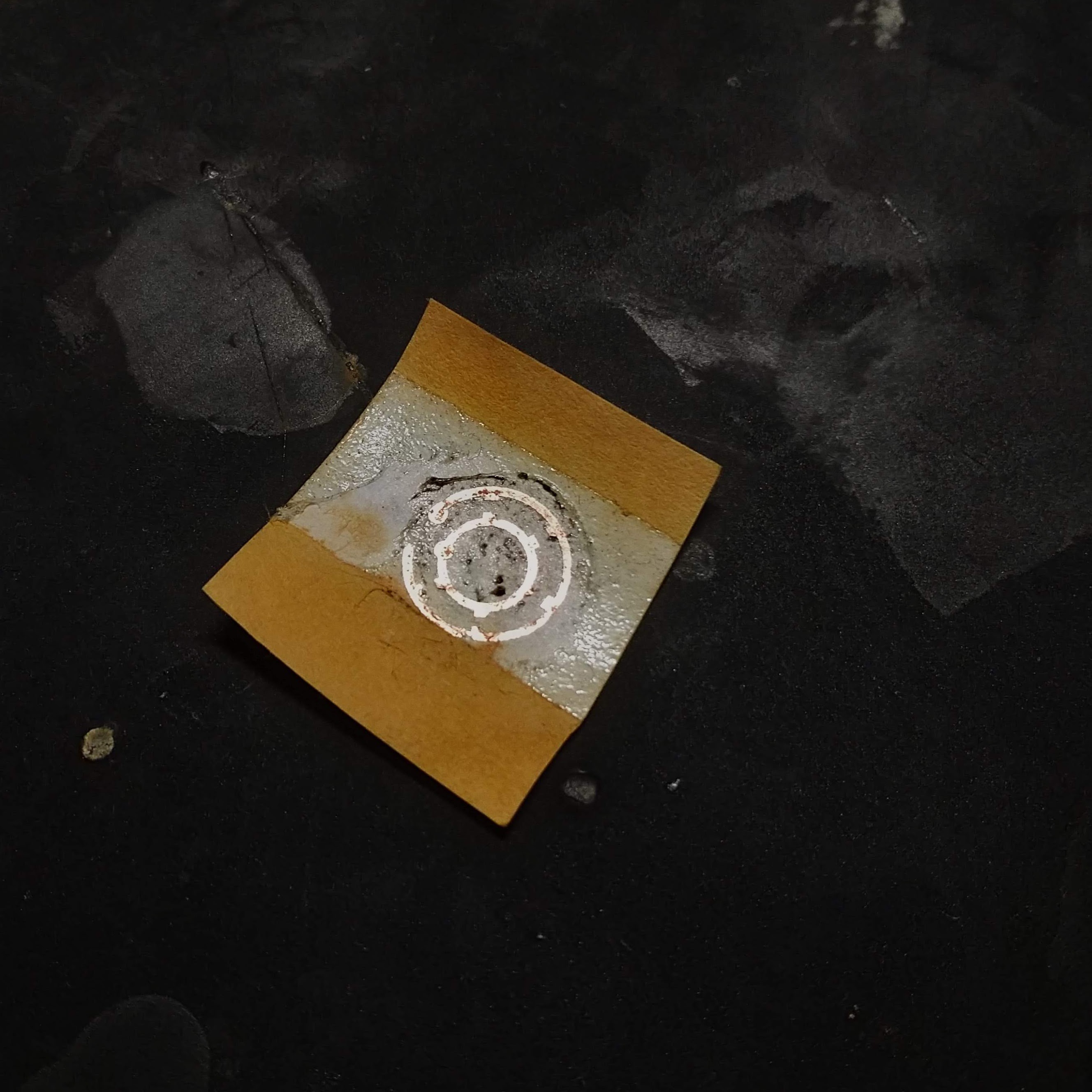
Now we are left with just the toner, tape adhesive, and the paper. The tape adhesive being the reason why there is still a white rectangle around the design.
![]()
The surprisingly tricky part of this process was getting the toner off the copper without ruining the board. Normally when etching your own circuit boards you can just go scrub them and the toner falls right off. Obviously that wasn't really an option here.
So I took to the acetone and cotton swabs again. Trying to swipe and rub the toner off resulted in the copper becoming unstuck from the paper. I found that gently dabbing all along the toner, rather than rubbing, would provide just enough force to slightly dissolve, and shift away the toner. This part of the process required the most trial and error and was very frustrating. If you caught the copper in just the wrong way, it may fold or lift off the adhesive still holding it in place. The acetone was also quite good at dissolving the adhesive holding everything in place, so I couldn't just soak the hold thing at risk of ruining the board.
I honed my dabbing technique and eventually could reproduce this paper thin layer of bare copper every time.
![]()
While everything was still anchored in place by the adhesive, it was now time to solder on the LEDs and wires. Unlike last time, I wised up and bought myself some solder paste. Some of which I squeezed into an insulin needle. This allowed me to deposit only the tiniest amount of paste that I needed to hold everything together, hopefully allowing me to avoid any extra material that I didn't need.
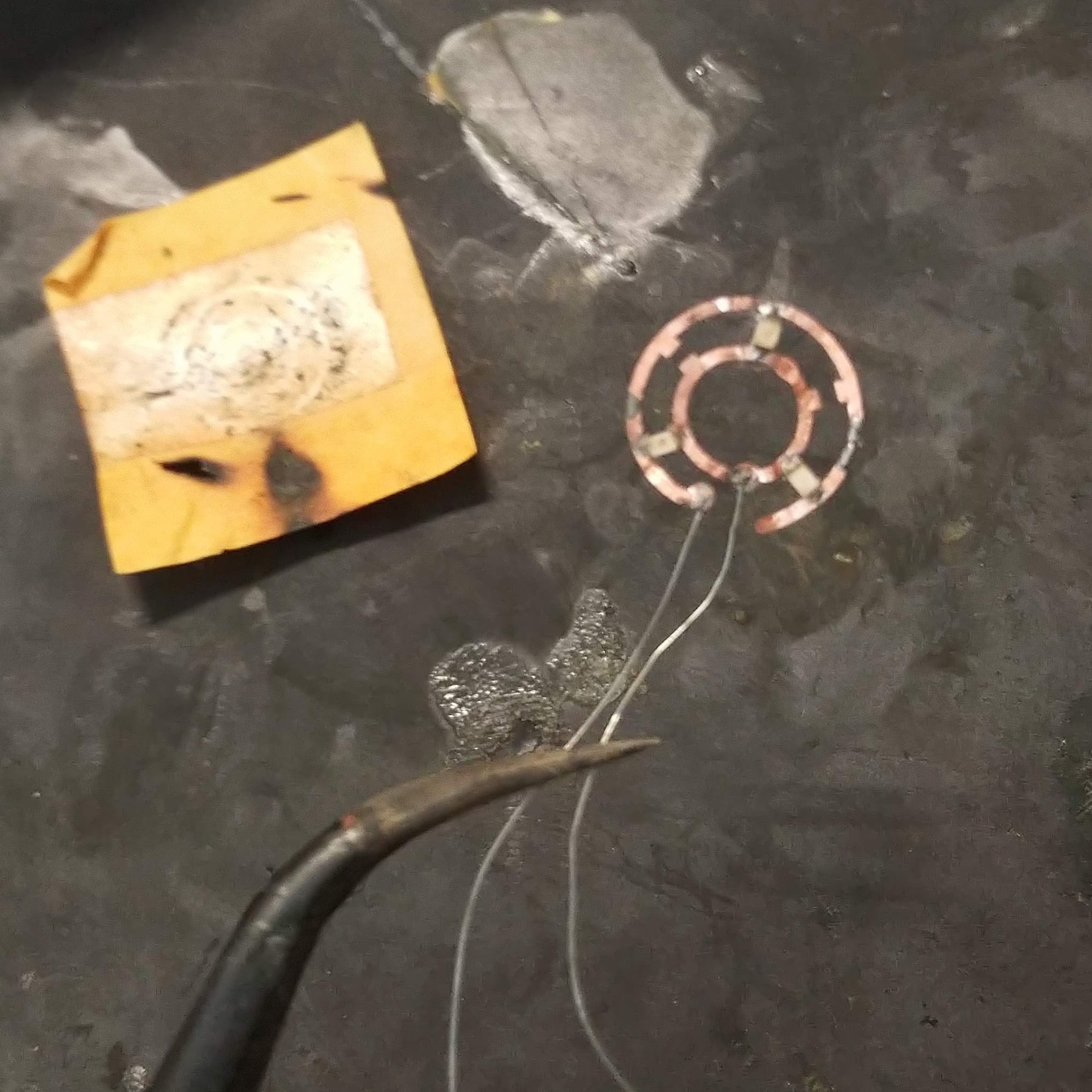
Because the paper was so thin and the parts so small, I was then able to melt the solder paste just by holding the piece of paper directly over my soldering, solidifying everything together. This whole assembly was then bathed in some more acetone to dissolve the rest of the adhesive, and the circuit was very gently, separated from the paper, leaving the final result below.
![]()
![]()
I think it kind of looks like a mini arc-reactor
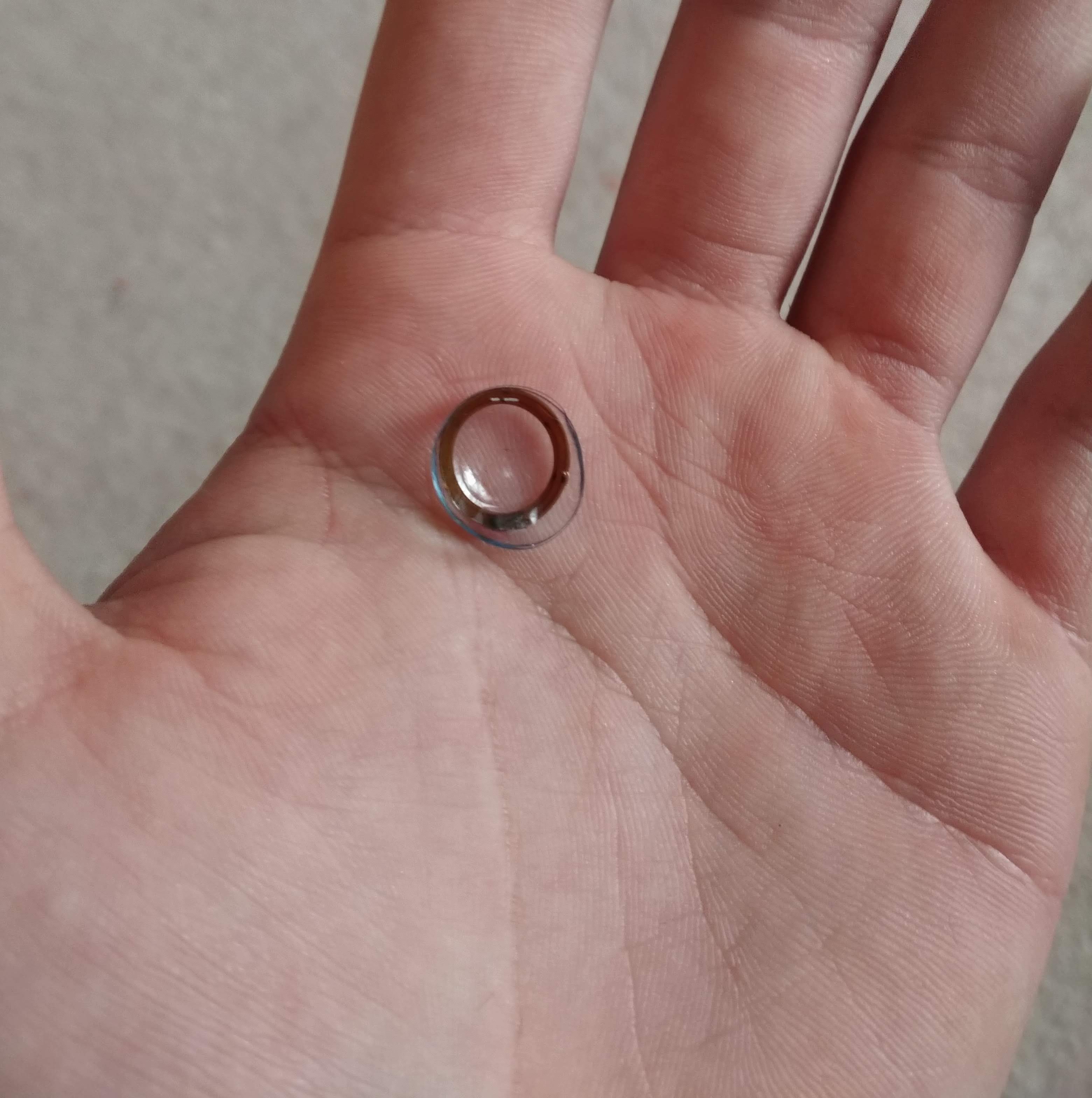
Finally all that was left to do is embed the whole thing in between two contact lenses, which is actually the easiest part of this whole process. It just kind of squired the two lenses and circuit boards in between my them and forefinger and waited until the lenses dried out a bit. This would then glue them together quite adequately.
![]()
![]()
And Viola! We have a nice glowing contact lense ready for eyeball insertion. I apologize for all the crappy pictures, but my phone really does not like taking pictures of these tiny things. It always seems to want to focus on jusssst the exactly wrong thing.
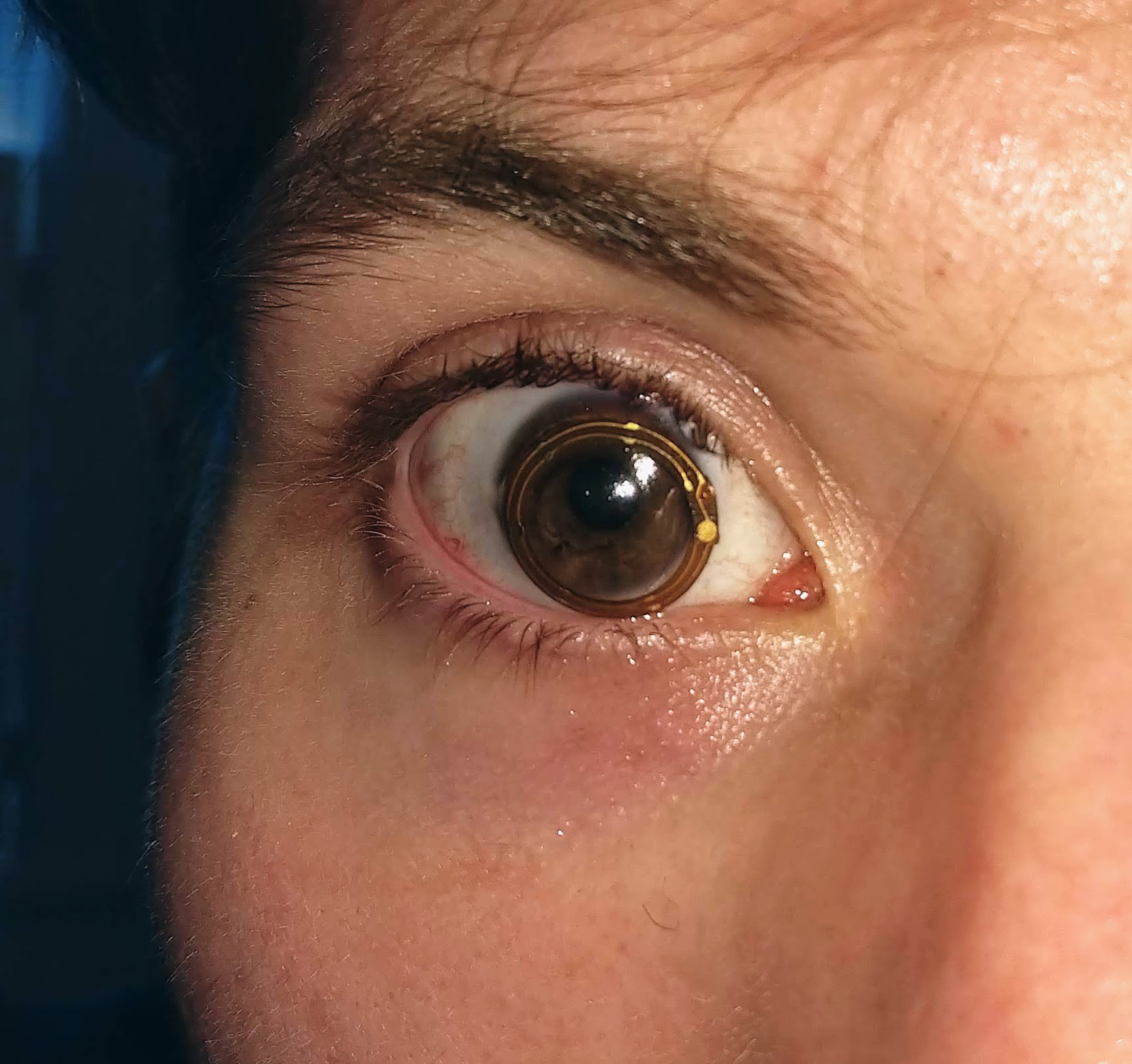
And of course we need the obligatory, eyeball pictures. After all, what would be the point of this project unless I actually risked scratching my corneas?
![]()
Pretty badass, right?
So there you go. I would consider this process a success! Once I got everything down it was relatively simple. However, as some of you noticed, I have not actually posted any pictures of my eyeball glowing....so this project is still uncompleted.
I am still running into a few issues:
- Bulk
- The entire assembly is still too thick for my top eyelid to slide over it without assistance. Whenever I blink, the entire lense gets pushed partially under my lower eyelid.
- I believe that if I switch to lower profile LED this issue can be mitigated
- Wires
- I have determined that it is indeed possible for wires to come out between you eyelids and not die. So that is good.
- The wires exert too much torque on contact lense when blinking and being handled
The wires are really the reason why I have not been able to take a picture with the LEDs turned on. It is quite the hassle to get the lense into my eye, and then try to finagle the two wires onto either side of a watch battery. They are just to bulky and any force on them causes the contact to either come out of my eye, or slowly separate the contact lenses holding everything together.
In terms of next steps, things are pretty straight forward. Get some more LEDs and the thinnest wires possible, and keep screwing up my eyeball!
- The custom made flexible PCB from Oshpark
-
The Tiniest of Circuit Sculptures
04/01/2019 at 21:09 • 0 commentsIn this exciting installment I continue to find new ways to possibly mutilate my eyeball, and I am unfortunately foiled!
From experimenting with the first prototype it was pretty clear that one of the first hurdles that must be overcome is the overall flexibility of substrate that the LEDs are placed on. The PCB is far less flexible than that contact lenses, and as such, the contacts are not able to force the PCB into the proper curved eyeball shape
First, let's rewind a bit. As I mentioned before, one solution to this issue would be to get rid of the PCB entirely (but then I don't think I could enter into the flexible PCB contest ;D). For those of you playing along at home, you will remember that my first attempt to dead-bug solder some leds into a ring did not go so well.
![]() This was using 0603(1608) SMD leds. They were crusty and didn't actually work. For some reason, the solder just wouldn't wick onto the wires, making it near impossible to actually attached the lights. I even made sure to burn off the enamel coating and everything! Once again, for those keeping track, it was a this point where I decided to have the PCB made, which is what you can see in my friend's eyeball featured at the top of this project. The thought of a substrate free design still seemed like the most feasible option though. So I ordered some more leds and decided to give it another shot.
This was using 0603(1608) SMD leds. They were crusty and didn't actually work. For some reason, the solder just wouldn't wick onto the wires, making it near impossible to actually attached the lights. I even made sure to burn off the enamel coating and everything! Once again, for those keeping track, it was a this point where I decided to have the PCB made, which is what you can see in my friend's eyeball featured at the top of this project. The thought of a substrate free design still seemed like the most feasible option though. So I ordered some more leds and decided to give it another shot. This time I stepped it up notch though, and attempted something only fools would think about....I used 0201 (0603) LEDs. That's right. I attempted to open air solder some of the smallest LEDs that money could buy. I guess I technically succeed? Before I show you the final result, let me first show you my method, because I think it was pretty clever.
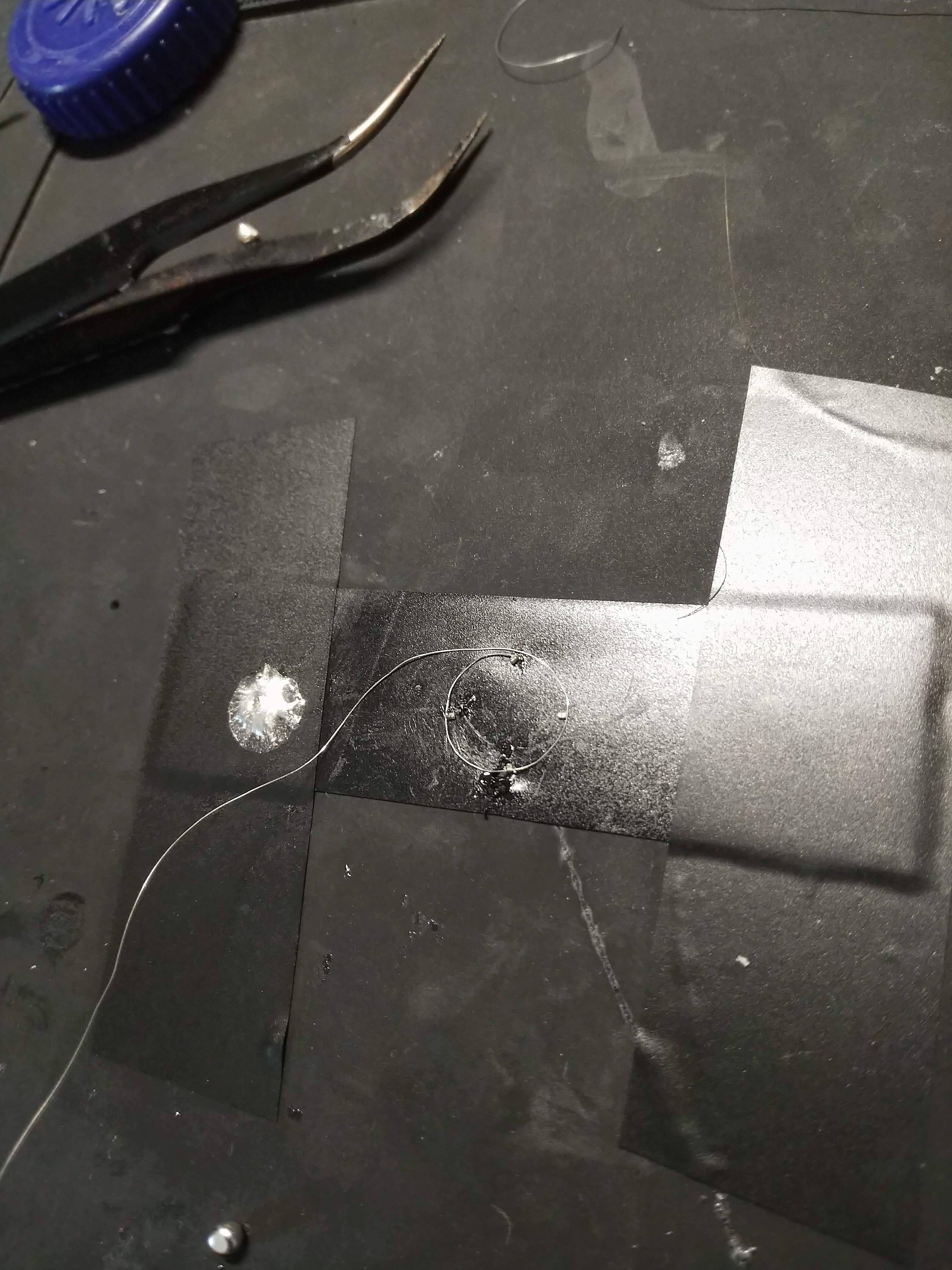
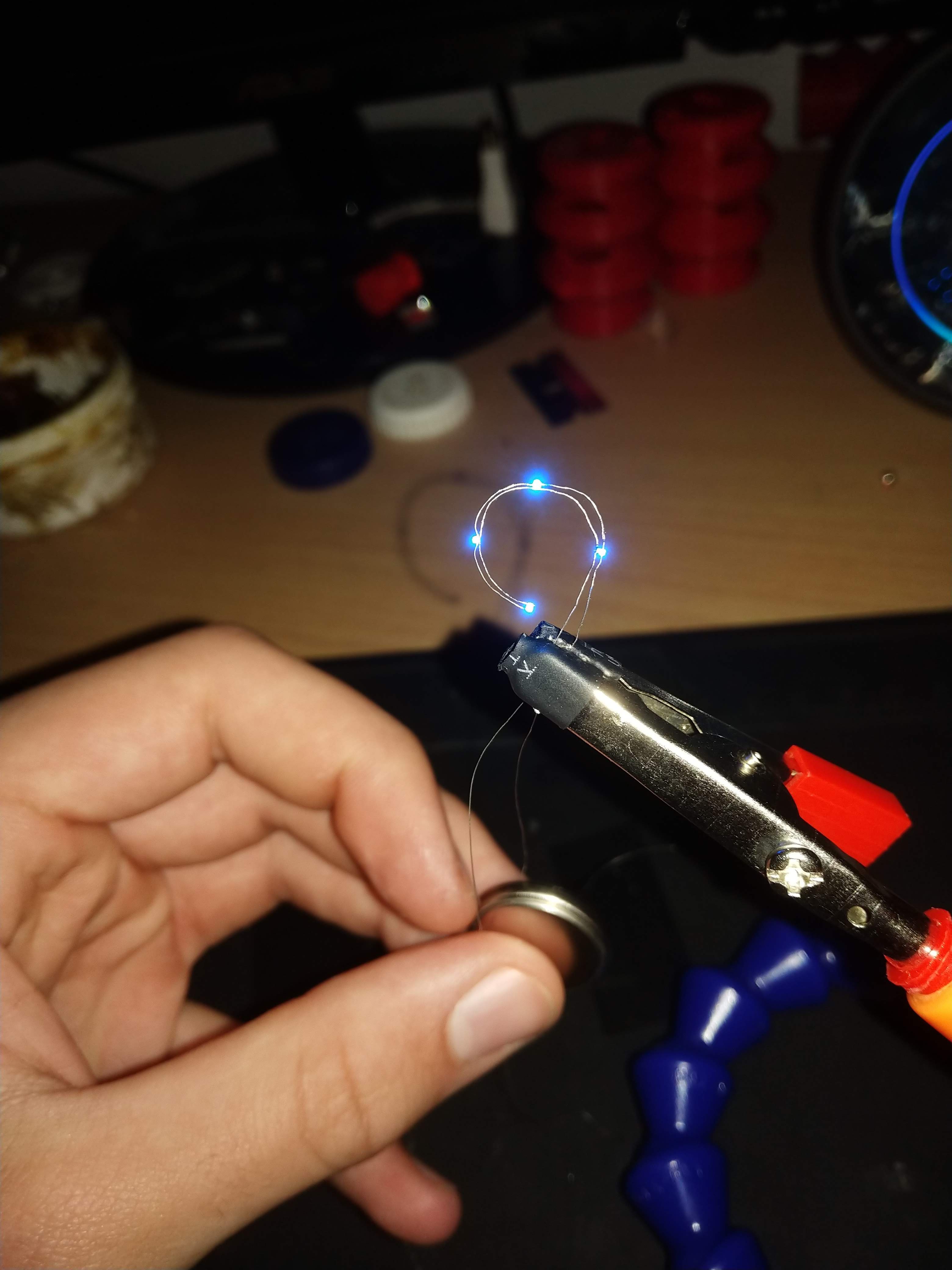
I quickly realized that the biggest issue that I was going to have was holding everything in place all at once. Thankfully, my good ol' friend Mr. Electrical tape came to the rescue. I placed once piece of tape sticky side up, and then tape it down on either side. This then gave me a nice sticky substrate that I could arrange my sand-sized LEDs on. Once they are in place, I can then go around to each and gently place a tiny amount of solder on them, working around in a circle one by one. It was soooo much harder than it sounded
![]()
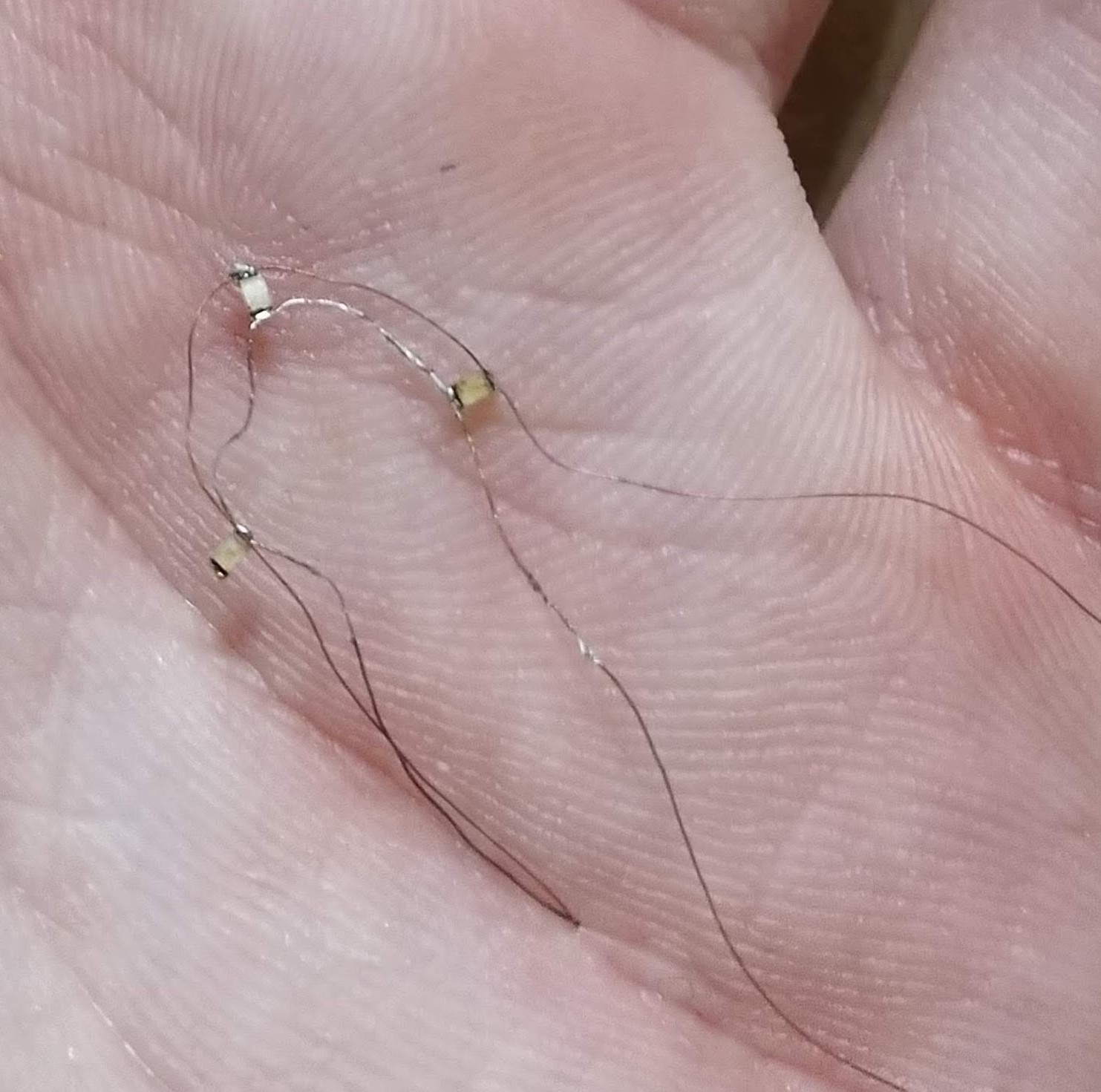
![]() I think it is kind of fun to look at the tweezers for some sense of scale. These were the smallest LEDs that I have ever worked with, and the whole process really helped me work on my mediation skills. All told I think I spend around 8 hours solder, breaking, adjusting, and fixing the solder connections. This is one of those things were you really want to nail the whole thing on the first go around. The more you futz with it, the crustier and more kinked everything becomes. I started over countless times until I eventually ran out of LEDs.
I think it is kind of fun to look at the tweezers for some sense of scale. These were the smallest LEDs that I have ever worked with, and the whole process really helped me work on my mediation skills. All told I think I spend around 8 hours solder, breaking, adjusting, and fixing the solder connections. This is one of those things were you really want to nail the whole thing on the first go around. The more you futz with it, the crustier and more kinked everything becomes. I started over countless times until I eventually ran out of LEDs.It is also worth noting that I switched my choice of wire as well. Rather than using hair thin enameled copper wire, I instead used some slightly thicker strands of wire that I extracted from an old IDE cable. This seemed to take solder much more readily, but it did increase the overall stiffness of the assembly.
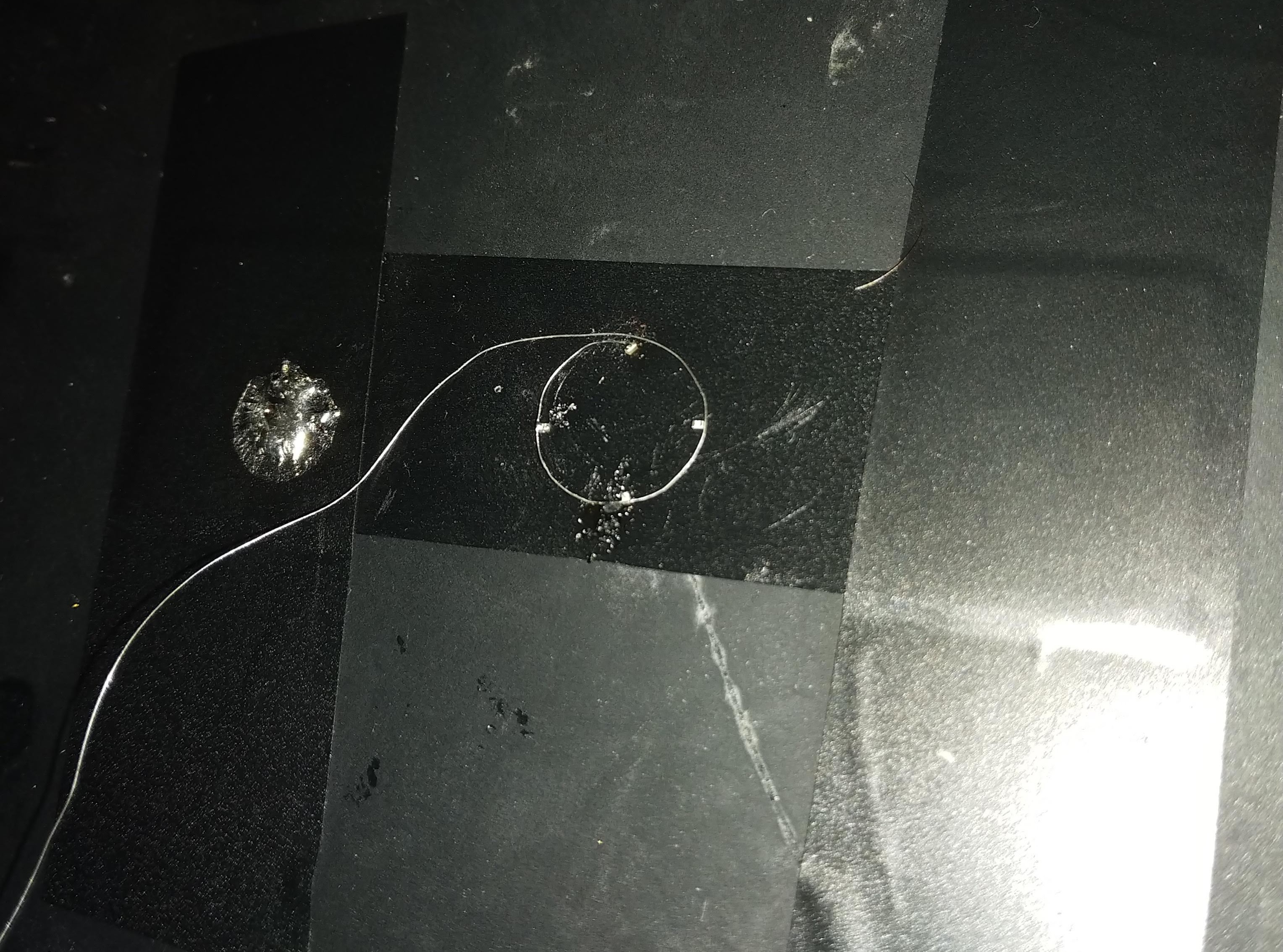
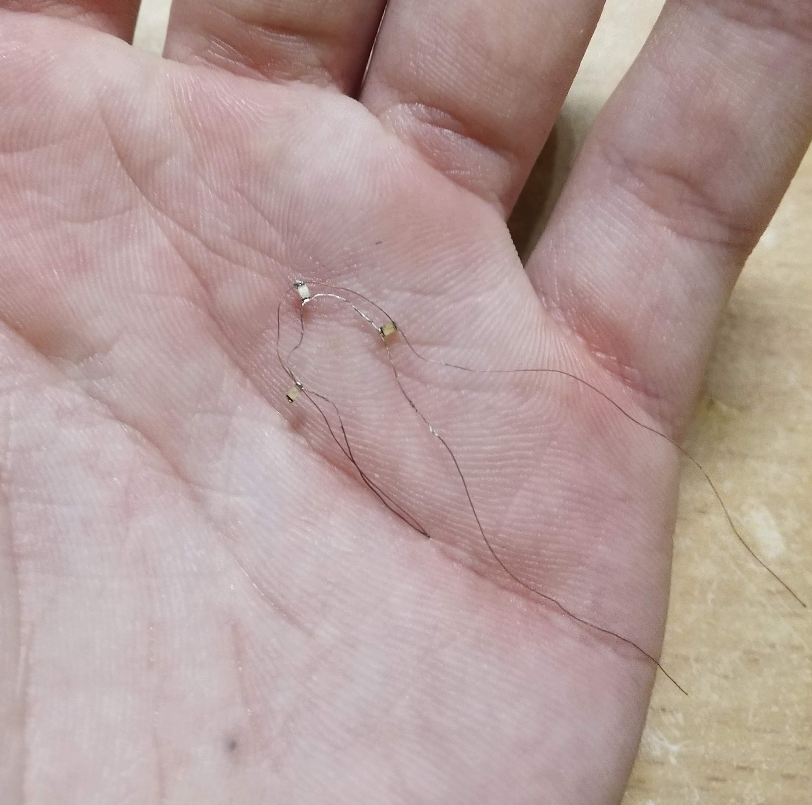
At the end of the day this was the final result.
![]()
![]()
![]()
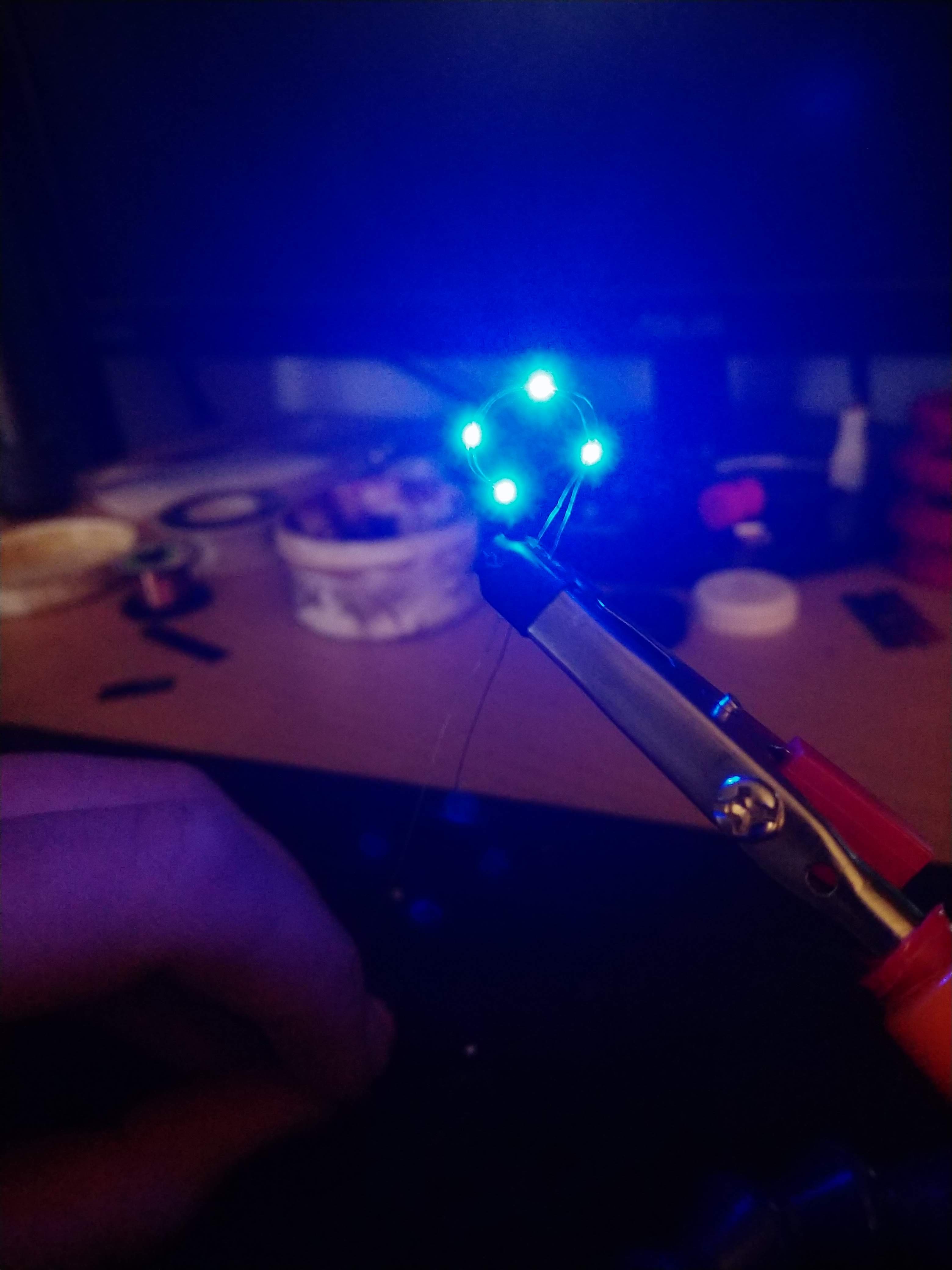
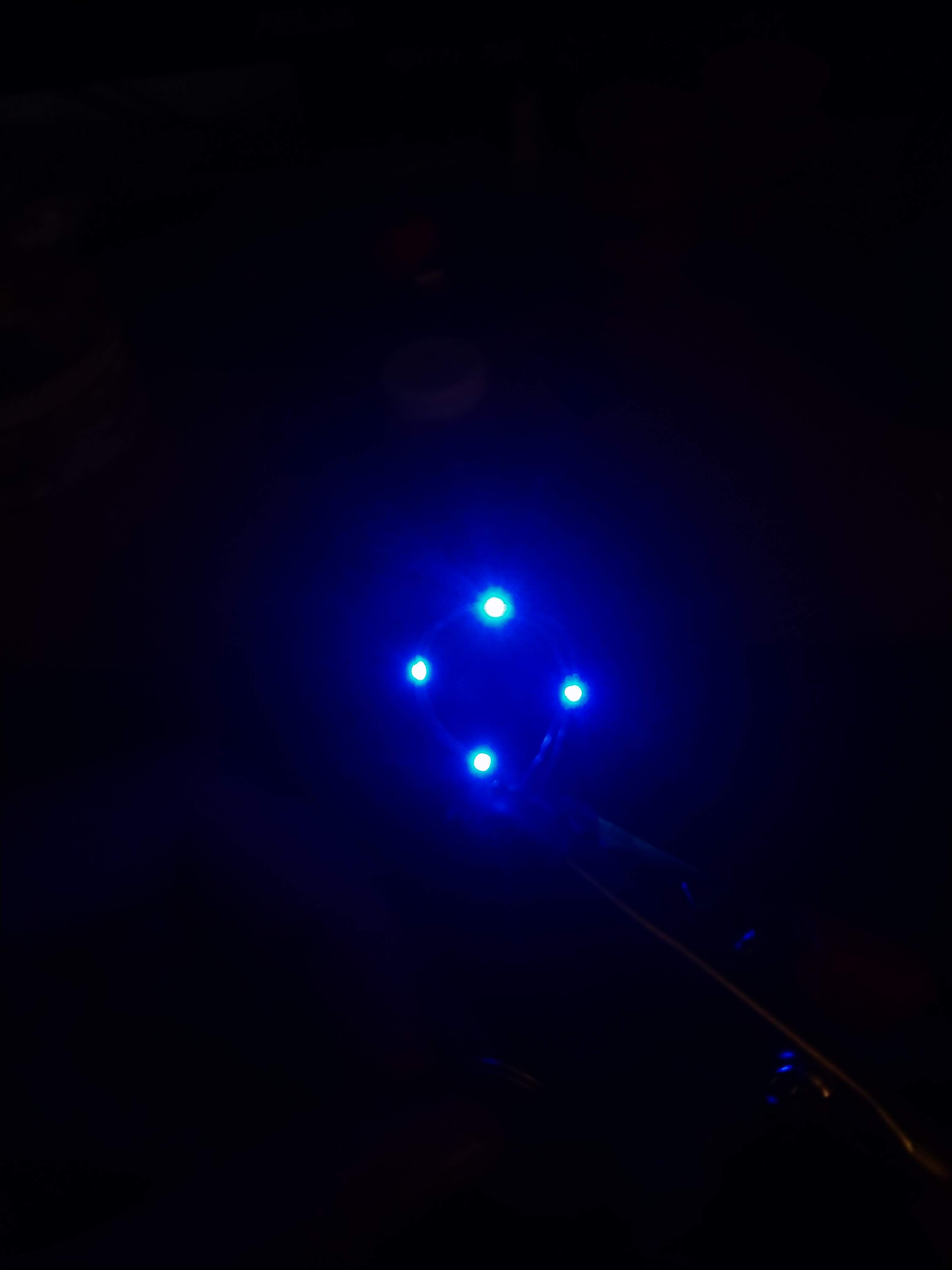
I am a bit disappointed that after all that work I couldn't get a better result. I have a feeling that if I had just one more shot at it I could have gotten something more presentable. However, everytime I went to set it up, I either accidently smashed it out of shape, or broke one of the solder connections. Regardless, I think what I was able to make has a very cool vibe to it. The LEDs are plenty bright enough despite being so so tiny.
This endeavour has also been pretty enlightening for the next steps I need to take. I still think that the dead-bug style cyborg eye has some potential when it comes to embedding into a contact lense, but it suffers from two major flaws:
- Repeatability
It took about 8 hours of work just to get the crappy pictures that you see above. I would really like other people to be able to replicate this, but not everyone has the young eyes and hands of an undergrad. So I think that it would be best to revisit the PCB option.
2. Light Leakage
Something that I initially overlooked when comparing the dead-bug vs. PCB approaches was light leakage. Theoretically, all of the light that comes out of the LED should shine away from your eye, so you shouldn't even really be able to tell if it is turned on. Of course this is the real world so some of the light will be diffused and reflected by the contact lense covering the LED. However, I noticed that substrate actually served somewhat as a shield, blocking a miniscule area of that reflected light, something that the dead-bug ring doesn't have.
That being said, I think that I am going to take another wack at getting a flexible PCB made, and I highly doubt that it will pass OSH Park's DRC. Oh Well! We will cross that bridge when we get to it! Anyway, I think that just about wraps it up for this misadventure. I still need to find a source of contacts that I can experiment with as I don't actually have a prescription and my friend ran out of old ones. If anyone has any ideas or want to send me some older, low power ones, please send me message!
As always any feedback or ideas are much appreciated. At this point I feel like I have heard just about every warning and concern out there, but if you come up with a new one do tell!
Until next time.
-
Welcome to the future
03/25/2019 at 02:06 • 0 commentsMy first attempt was a bit of a misguided way to spend a Friday night.
I had bought some super thin enameled copper wire and blue 603 smd LEDs with the thinnest profile that I could find. Based on the Applied Science video, it seems like one of the biggest issues that he ran into was the thickness of assembly. Keeping everything nice and slim is going to be the real name of the game here. I figured that the best I could do would be to solder some leds in parallel Jacob's Ladder style, and then bend the wire into a ring. Once that was done I would then seal it between two contact lenses, leaving the wires poking of one side.
![]()
As you can see, that didn't work too well. I learned pretty quickly that bending straight things into a circle is generally pretty hard to do. This was pretty discouraging because I figured that this was my best chance at getting the thinnest lense assembly possible. I think that in the future I might try this approach again, but at this point I was getting sick of dealing with all these fiddly wires and opened up Eagle to vent my frustration into.
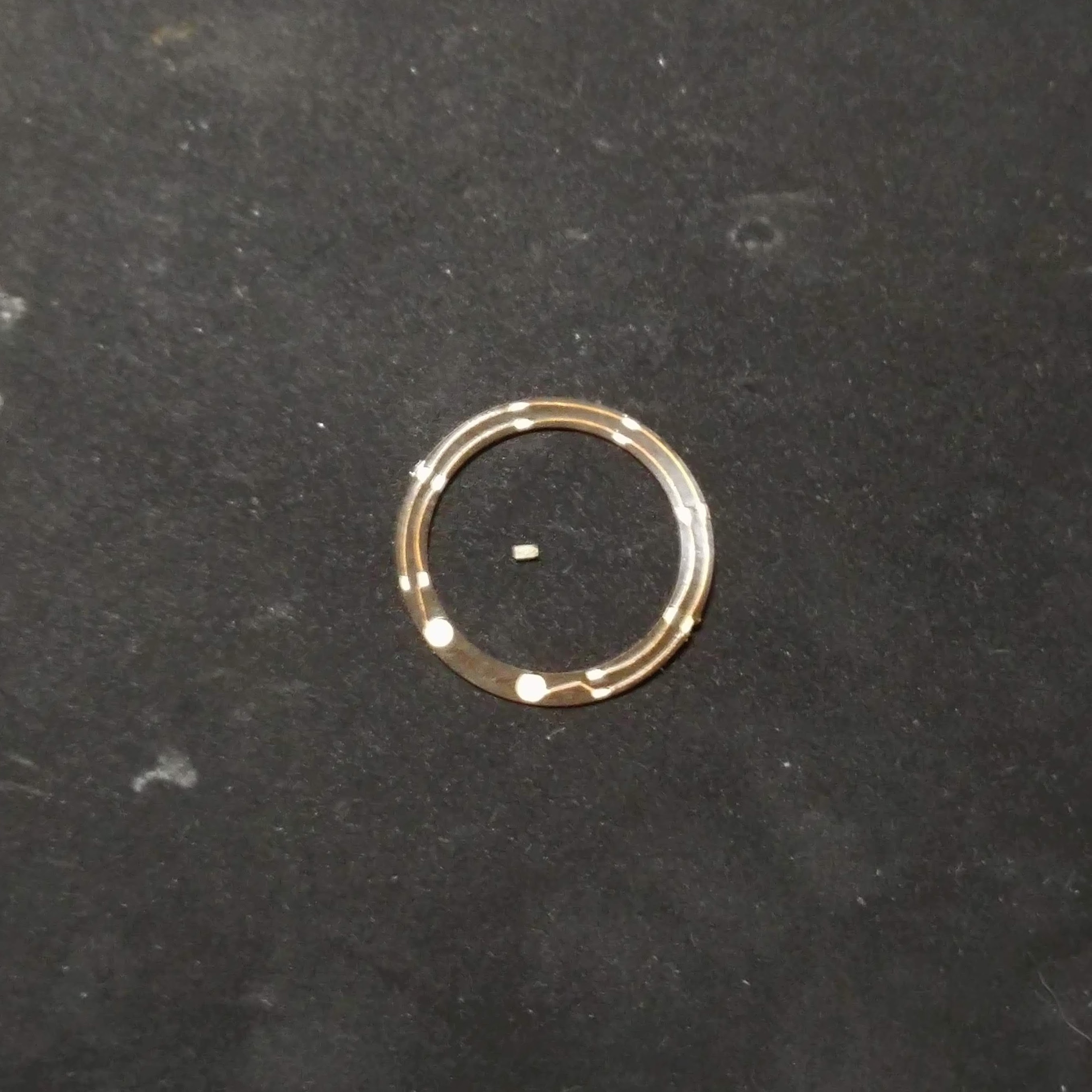
My intention was now to create the smallest and most flexible PCB that OSHPark would attempt to make. After eyeballing some measurements (heh), I whipped up a ring with leds evenly spaced and wired parallel . Unfortunately I lost the file, but not first before having a few made. The final result is below, with the 602 led in the middle for scale.
![]()
I was a bit nervous about how bright these little guys were going to be. I had to try to optimize voltage, luminocity, and thickness. Ideally the LEDs are just going to be wired up to little 3v watch batteries stuck to the side of the uses head. Unfortunately, the wires coming out of your eyeballs are going to hurt like the devil. The problem is that there really just isn't enough space on your eyeball to make the whole wireless power transmission work well. So killer eyeball wires it is!
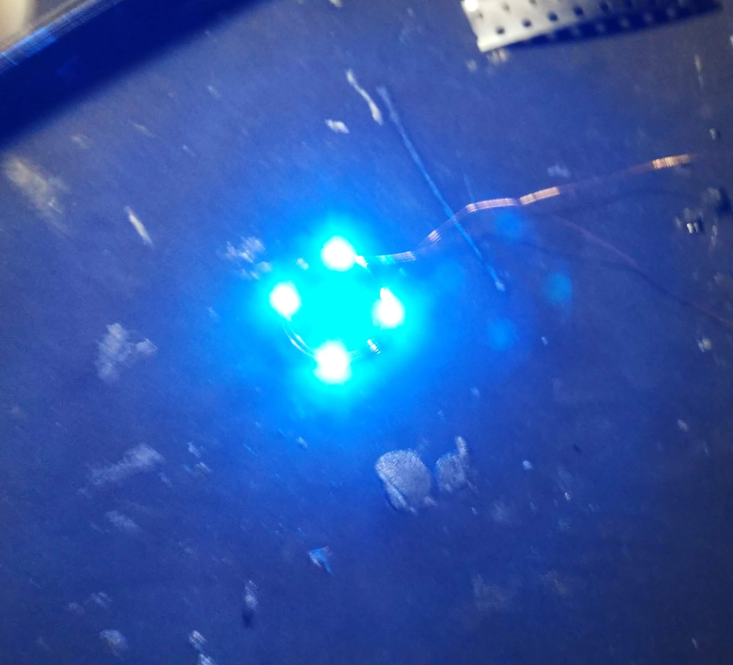
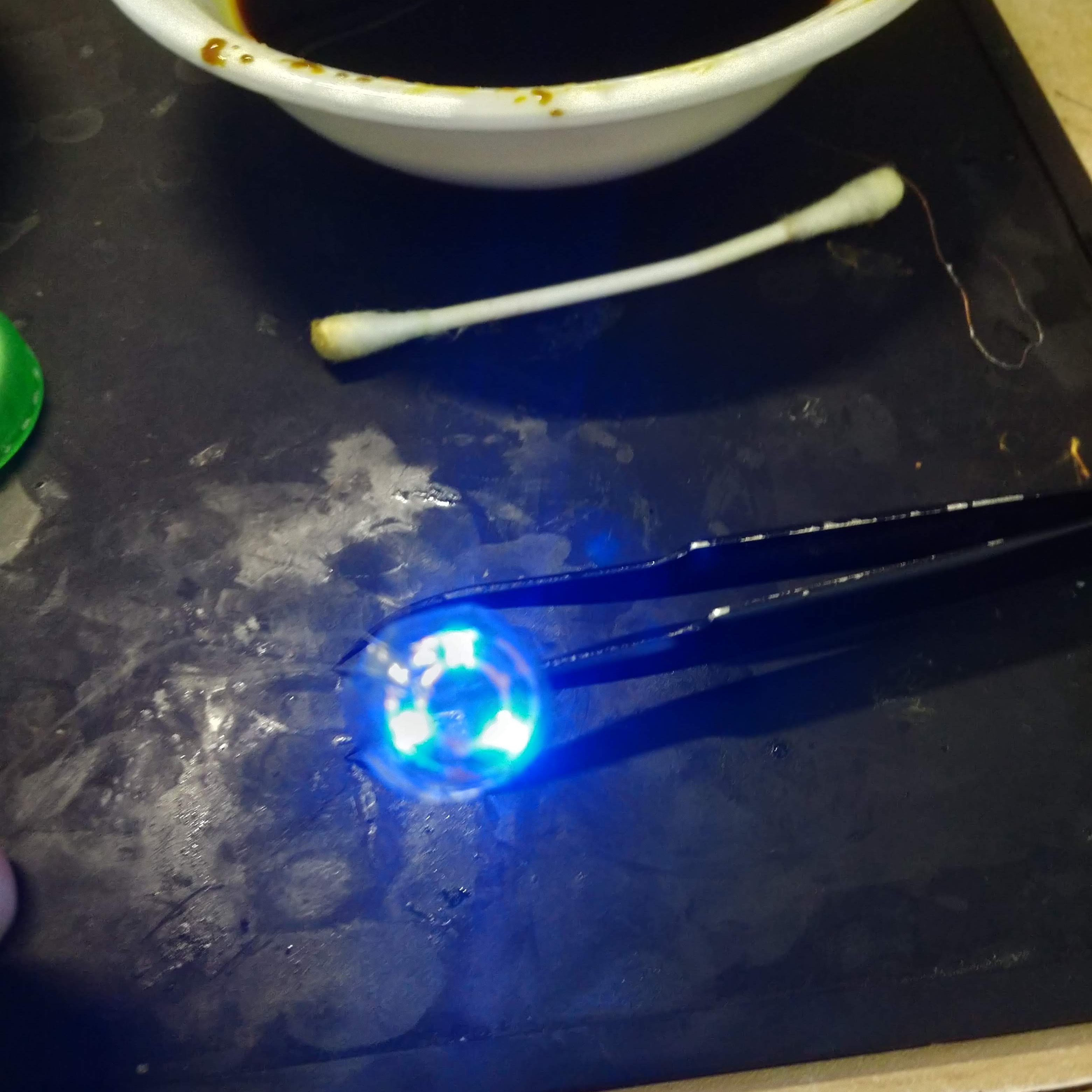
Once I soldered everything and hooked it up, I was incredibly impressed with how much light these little guys put off!
![]()
(Sorry for the shaky picture, I was just so excited!)
Now obviously the electronics side of this project was pretty trivial. So now it is more of a matter of how to actually get this light ring in your eye, thus catapulting you into the cyberpunk world of your dreams.
![]()
Right now the current method that we have come up with is to simply sandwich the ring into between two contact lenses. This only sort of works, and we still need to find out how to bond the two lenses together without clouding them and keeping them flexible. The other issue is that the ring should ideally be able to conform or match to the curvature of your eyeball, something either said than done. Right now method is to cut a gap into the ring, and then glue the two ends together. This causes the pcb to adopt somewhat of a conical shape, and it works to some degree. However it is far from an ideal solution.
Either way, we did in fact manage to get a test ring into my friend's eye, and I have to say, it looks pretty cool.
![]()
![]()
Obviously there is still a little ways to go before we all have glowing eyes, but like I said, it's a start. I plan on making another, thinner PCB and maybe trying to to use 302 leds to cut down on the material of the circuit board. As you can see in the picture above, the assembly is bulky enough that every time the user blinks, it get pushed down the eye, and sometimes even comes out entirely.
Also it should go without saying that there is some inherent danger in this project. Generally bright lights shining directly into eyeballs, and sharp objects near them are a recipe for disaster. However, it is worth noting that all of the light from the LEDs is shining directly out of the user's eye, so there is little danger of blinding yourself.
Let me know if you have any thoughts, suggestions, or words of warning!


 This was using 0603(1608) SMD leds. They were crusty and didn't actually work. For some reason, the solder just wouldn't wick onto the wires, making it near impossible to actually attached the lights. I even made sure to burn off the enamel coating and everything! Once again, for those keeping track, it was a this point where I decided to have the PCB made, which is what you can see in my friend's eyeball featured at the top of this project. The thought of a substrate free design still seemed like the most feasible option though. So I ordered some more leds and decided to give it another shot.