-
1Let's Build
![]()
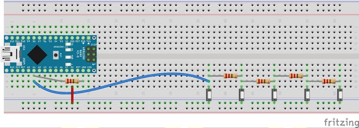
- First connect five push switches to a bread board.
- Of course you can connect maximum of 1023 switches theoretically to a 8 bit micro controller like Arduino.
- then inter connect resistors in between the push switches as shown in the diagram.
- connect the other end of all the switches to 5v of Arduino, as you can see here I have connected the in such a way that one end is connected to the blue line of the beard board which is connected to the 5v.
- then from the end of the final switch connect a wire to analog pin A1 of Arduino.
- then connect a resistor across A1 and GND of Arduino, which is for pull down, That is to keep the value to zero when no switch is pressed.
![]()
-
2Connect some LEDs
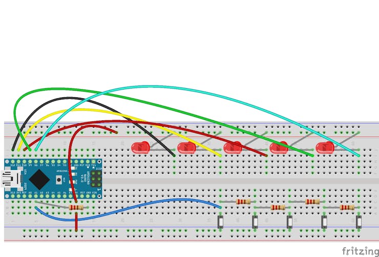
Let's connect some LEDs to check the functioning of our circuit.
Connect the LEDs as shown in the circuit,
- connect all the positive terminal all LEDs to the 5v.
- connect the negative terminal of each LEDs to the Digital pin D12 to D8 of Arduino respectively.
- Practically we have to connect the LEDs through resistors for good life time.
![]()
-
3Coding
Take a look at the program, all the lines are commented properly. Now let's upload the code and see it in action.
//www.diyusthad.com //https://www.youtube.com/channel/UCjwtJsOrZyH7E6sBr_YJSeA //Code by Najad #define sw A1 //name for analog pin A1 #define led1 12 #define led2 11 #define led3 10 #define led4 9 #define led5 8 void setup() { Serial.begin(9600); pinMode(led1,INPUT); digitalWrite(led1,HIGH); //setting led1 pin HIGH ie LED will be off according to our circuit pinMode(led2,INPUT); digitalWrite(led2,HIGH); //setting led2 pin HIGH ie LED will be off according to our circuit pinMode(led3,INPUT); digitalWrite(led3,HIGH); //setting led3 pin HIGH ie LED will be off according to our circuit pinMode(led4,INPUT); digitalWrite(led4,HIGH); //setting led4 pin HIGH ie LED will be off according to our circuit pinMode(led5,INPUT); digitalWrite(led5,HIGH); //setting led5 pin HIGH ie LED will be off according to our circuit } void loop() { Serial.println(analogRead(sw)); // reading and printing the values from analog pin A1 if(analogRead(sw) >197 && analogRead(sw) <207 ) digitalWrite(led1,LOW);// LED will turn ON else if(analogRead(sw) >248 && analogRead(sw) <258) digitalWrite(led2,LOW);// LED2 will turn ON else if(analogRead(sw) >333 && analogRead(sw) <343) digitalWrite(led3,LOW);// LED3 will turn ON else if(analogRead(sw) >509 && analogRead(sw) <514) digitalWrite(led4,LOW);// LED2 will turn ON else if(analogRead(sw) >1015 && analogRead(sw) <1023) digitalWrite(led5,LOW);// LED2 will turn ON } -
4Applications
- Keypad
- Full sized key board for Arduino.
- Custom mini keyboard for your raspberry pi tablet etc..
If you can think of another application post it in the comments.
Thanks.
-
5Working video
100+ Switches in a Single Pin of Arduino
Did you run out of input pins, don't worry here is a solution without any ICs.
 Najad
Najad


Discussions
Become a Hackaday.io Member
Create an account to leave a comment. Already have an account? Log In.