 Joris Wegner
-
1Caution
USE THIS DEVICE AT YOUR OWN RISK. Using the original software to create and use patches as well as the recommended parts, the unit should use much less current then a usb port can deliver. The video circuitry should be isolated well enough from the controller circuit that is connected to the computer, but I'm not a professional and don't really know what I'm doing. I am not responsible for any damage that could occur while using this device.
-
2Make 20 vactrols
![]()
In order to control the video effects via MIDI, I needed a part that could override the potentiometers. For full effects, I need less than 30 ohms, to switch an effect off completely, a resistance of more than a few kohms would be desirable. I couldn't find a semiconductor solution that really seemed to do the job for a reasonable price and very low-resistance Vactrols like the vtl5c4 are way too expensive. A cheap find on ebay turned out to be a scam. So I decided to make my own vactrols:
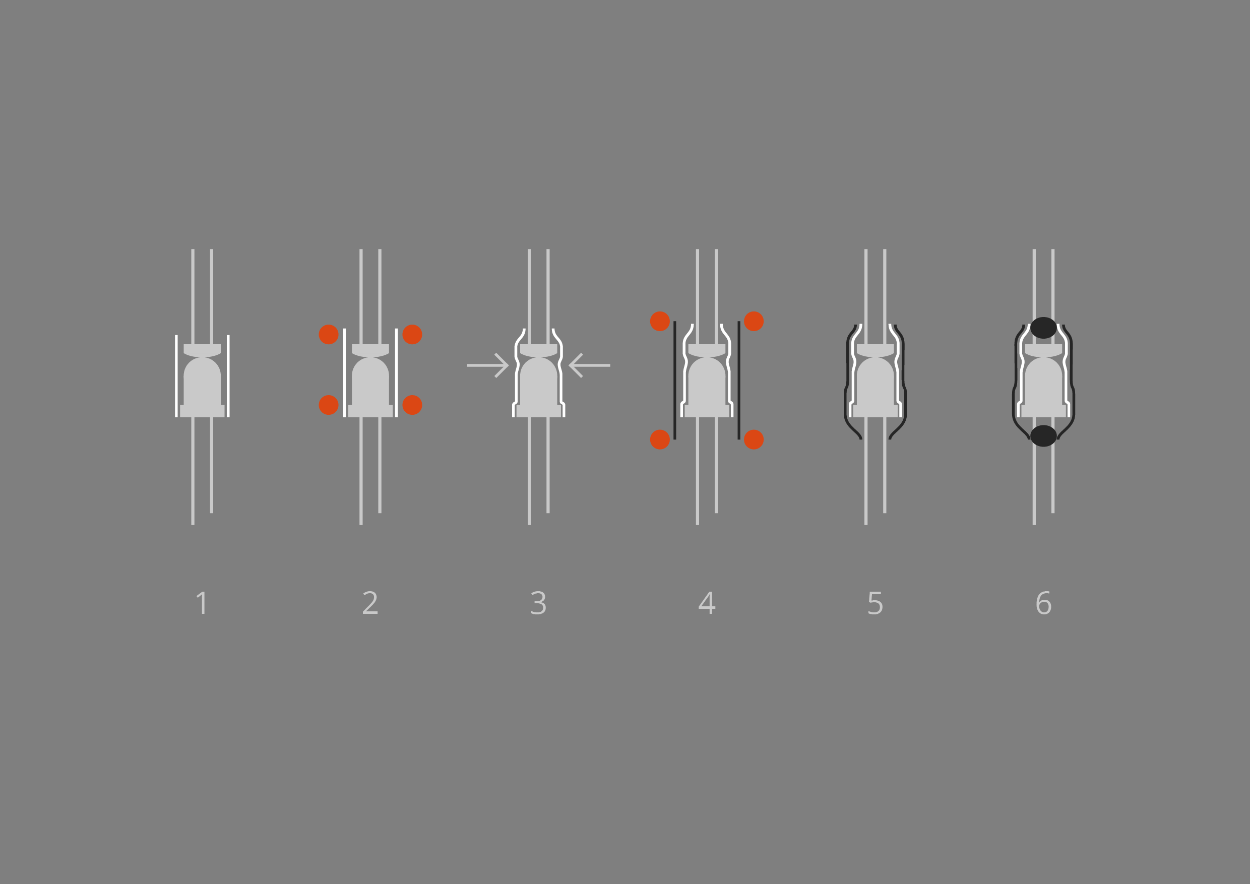
I chose RND components high-power white LEDs for their low cost and brightness. They emit 27000mcd at an angle of 15°. When put directly in front of a GL5506 light-dependant resistor and connected to 5V with a 120 ohm resistor, the LDR reaches a resistance of below 60 Ohms. Therefore, most of the effect channels of the PHOSPHOR use two vactrols in parallel.
1 - The LED and LDR are touching each other. A ~12mm long piece of shrink tubing with a diameter of slightly larger than 5mm is placed over the components as shown.
2 - Heat is applied to shrink the tubing near its ends without shrinking the middle too much to prevent it from blocking the light path (step 3).
4 - A ~16mm long piece of slightly larger black shrink tubing is again heated mostly near the ends to give the vactrol more stability and keep light from escaping.
6 - To really encapsulate the vactrol, I put a drop of black nail polish into both openings.20 vactrols are needed in total. for each channel one vactrol sits above, another under the board. Exceptions: Just one vactrol each is needed for the fifth and the eighth channel from the left. I suggest to test and measure the vactrols before soldering them in, some of mine had too much resistance and were replaced.
-
3Soldering the components
Soldering should be pretty clear. Please note that the images in the gallery show my prototype, the silkscreen layer of the available 1.1 gerber files now has all the components labeled and some values changed.
-
4Programming
![]()
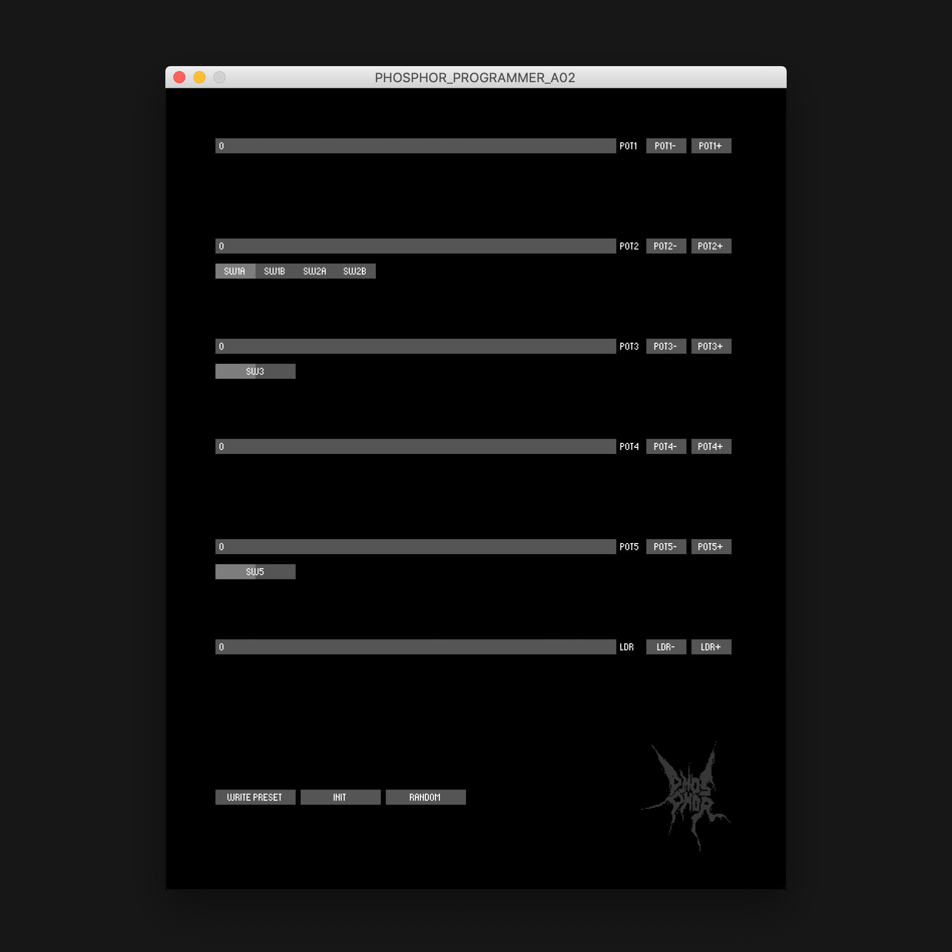
Connect an analog video source to the input (PAL/NTSC) and some kind of monitor to the output. A CRT monitor works best. Projectors and other devices might need time base correction first. Upload the PROGRAMMING sketch to the Arduino, then use the corresponding Processing sketch to find interesting patches.
Use the sliders to roughly adjust the brightness of the LEDs controlling the video circuit. The buttons on the right side of the sliders can be used for fine adjustment.
0 = effect is off, 4095 = full effect (probably resulting in synchronisation loss).
Exception: The topmost slider adjusts the amplification of the video enhancer.
(0 = full amplification, 4095 = black screen).
The toggle switches under some of the sliders allow for further variation.
PLEASE NOTE: The photoresistors I used have a highly exponential resistance curve. That means that the difference between the values 0 and 1 is much greater than between the values 4094 and 4095.
RANDOM: Randomize values and switch positions.
INIT: Set all values to zero and the toggle switches to their inital state.
WRITE: Print the current slider and switch values. This is a preset that can be copied/pasted into a matrix in the PHOSPHOR_MIDI arduino sketch for using it later with MIDI controls. -
5Use
After you have found enough patches you like, paste them into the matrix of the PHOSPHOR_MIDI Arduino sketch and change the variable numberofpatches accordingly.
A MIDI ON command on CHANNEL 1 selects one of the patches stored in the matrix to trigger the glitchy effects.The first matrix entry should be left as it is. Sending a C4 note on MIDI CHANNEL 1 will then disable all effects. This sketch only reacts to MIDI ON commands. This way, you can send the desired note multiple times in a short period to reliably change the patches if you encounter any problems.
There are no presets because I believe that the tolerances in the hardware are too large to make patches that work well on all devices.
PHOSPHOR Video Distortion
PHOSPHOR is a MIDI-controllable distortion device for analog video. I made it to create glitchy video projections in sync with Ableton Live.
Discussions
Become a Hackaday.io Member
Create an account to leave a comment. Already have an account? Log In.