-
Pt.1 Sensor Design and Prototyping
03/27/2019 at 15:30 • 0 commentsFull video on this subject (this is literally the script): https://www.youtube.com/watch?v=Psy6lRcdGtk
Introduction
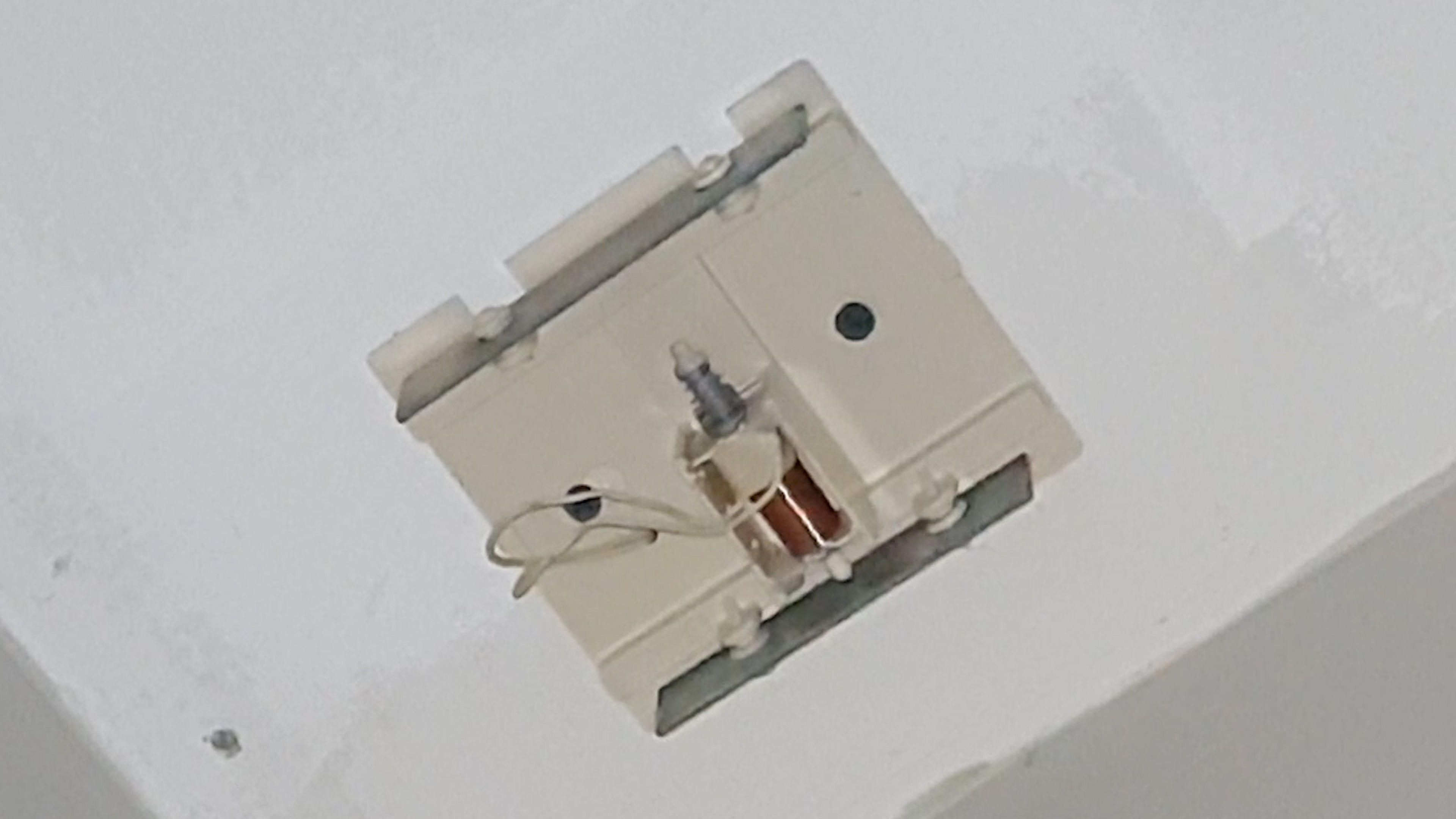
Old houses, like my parents’ home, comes wired with simple electromechanical doorbells. They’re a simple electromagnet with a metal rod that when energized, gets pulled to one side and hits a metal plate, like a vibraphone. When the power is cut, a spring on the other end of the rod will accelerate it to the other direction and hits another plate. These plates generally emit different tones when hit, that’s why these doorbells are known for their chime: DING-DONG.
![Doorbell chime Doorbell chime]()
Doorbell chime That’s all there really is to it.
Not that I'm throwing shade at this technology for its simplicity, in fact simple is definitely better all else being equal. But this dumb ding-dong machines are hard to expand on. Adding another chime somewhere else in your house will require a ton of wiring that will be hard to hide and expensive once you realized the mess you made and call someone to repair it.
Modern approaches like the Nest Hello or Ring Video will require you to gut all of your system and replace it with their proprietary hardware and protocols, not to mention the elevated price tag, questionable privacy and perhaps redundant camera on the doorbell.
Don't get me wrong, it a good deal if you want something to work right off the box, but they’re not exactly what I am looking for.
See, my dogs are getting old, and now you can't rely on them to warn you when someone is ringing the doorbell, especially while everybody else is watching a game. Adding another chime would be the easiest solution, but there simply wasn’t a pretty way to place cable all the way to the living room. And even then, a chime might not be heard in the middle of a goal and it would definitely disturb your binging session.
But how would do you notify someone that the doorbell is ringing without being intrusive or ignored? Well, you could make a sign the lights up whenever someone rings the doorbell. But that’s easier said than done.
So, in this series of videos, we will build just that. A Wi-Fi enabled, smart and visual doorbell system that will light up a sign when someone rings the doorbell as well as many other IoT feature that can be coded in.
The Problem
In this first post we will focus on building a working prototype of the sensing part of the system. The doorbell sensor. The sign and other aspects of the project will have their own post.
To tackle this, is a good idea to define exactly what we need. Let’s start with the basics, then we'll add additional features and characteristics as we go along. First and foremost, we need a way to detect when someone is ringing the doorbell. Secondly, the mcu needs to process the signal and communicate with the sign. And finally, the MCU needs to be able to run on batteries for a long time. This breaks up the design into 3 problems we can solve, detection, communication and power.
Part 1 - Detection
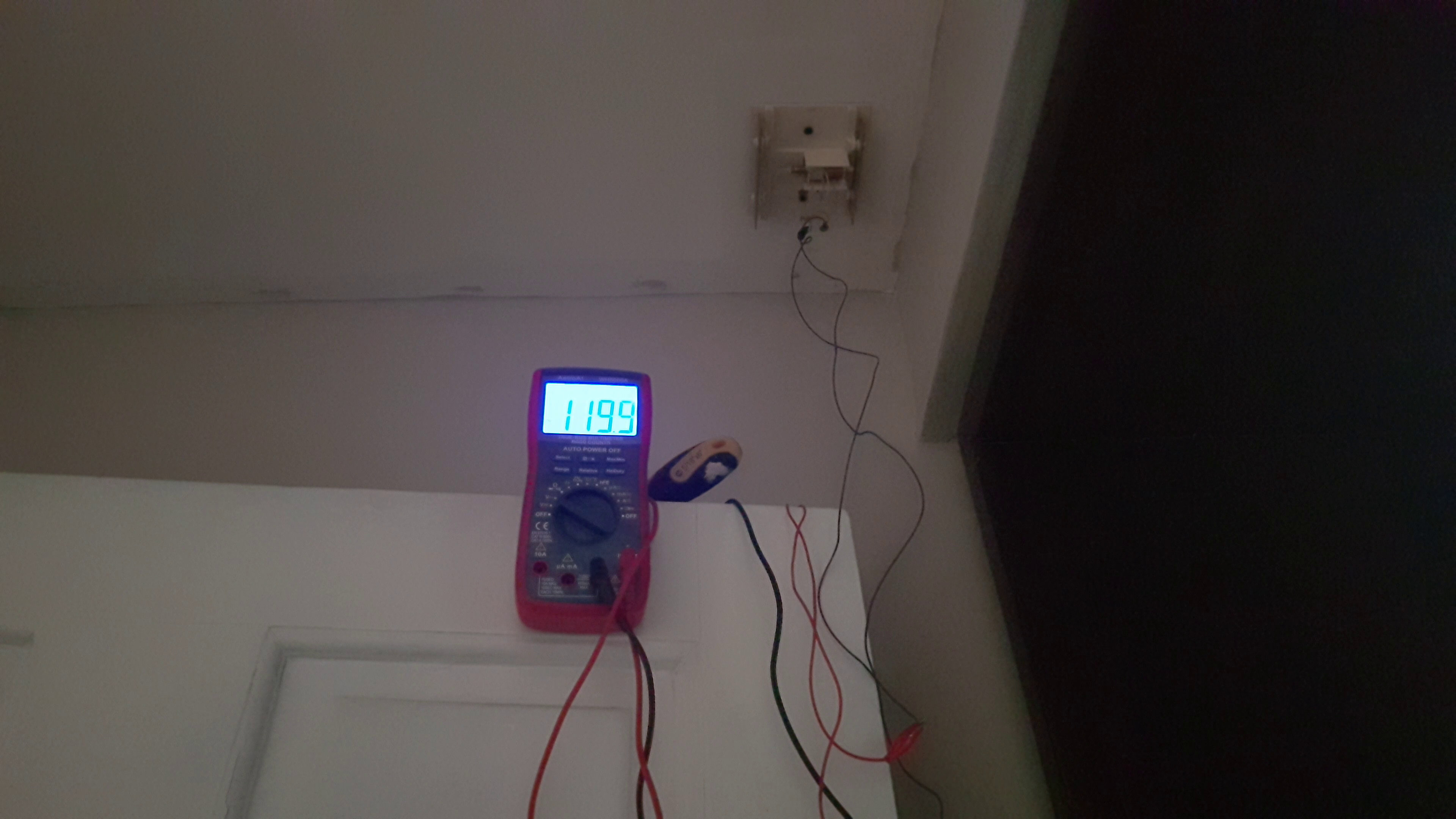
For the first problem, there are multiple ways to check is someone is ringing the doorbell, you could sense the loudness of the plates with an acoustic sensor or the movement of the rod or even the strength of the magnetic field of the coil for example. For multiple reasons, the most reliable way to test if someone is ringing the doorbell is sensing the voltage at the coil. In my case, the doorbell's solenoid is operated with 120v ac 60hz. This may be different on your house.
![My doorbell works with 120V AC My doorbell works with 120V AC]()
My doorbell works with 120V AC A simple and compact way to detect an AC signal is to build a simplified transformerless power supply.
Transformerless power supplies or TPSU are what’s typically used in compact low power applications like smart relays and many other IoT devices. They work in a similar fashion to regular power supplies but instead of relying on a transformer to lower the voltage level to a usable level, they use the reactance of a capacitor (also known as X) to do cause a voltage drop without dissipating any extra heat in the process (ideally, of course). The mathematics behind these can get a little bit complex ;) and subject to another video. In the meantime, you can refer to this Hackaday article. After lowering the voltage, rectification and regulation is done in a similar fashion as their non-transformerless power supply.
Because we don’t need the power supply to supply stable power, we can make a few compromises that will enhance several characteristics of our design. For example, the filtering cap should be designed to be small enough to have a quick response, but big enough to eliminate the ripple on the signal. And the full bridge rectifier can be replaced by a half bridge since we are not consuming that much power, effectively reducing complexity and board space. Now each time we have 120V AC on a coil, the TPSU quickly output a dc voltage.
To isolate the mains from the rest of the circuit, we add an optocoupler and resistor to the output of the TPSU. Optocouplers like the PC817 is just an led and phototransistor in a chip. When the LED shines, the phototransistor will get biased and current will start flowing from collector to emitter. With the appropriate circuit you can sense the signal without the need to be galvanically connected to the mains.
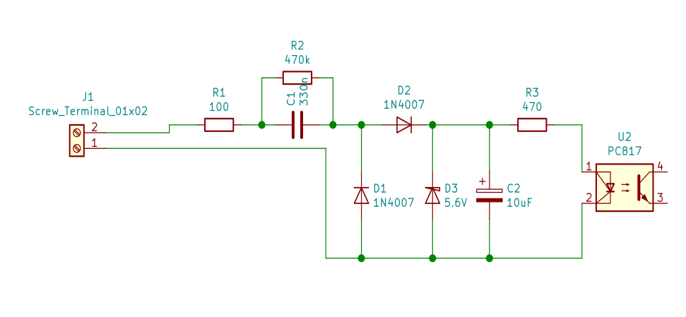
To finalize the high voltage part of our circuit, the anode of the LED is connected in series via current limiting resistor to the output of the TPSU and the cathode is connected to the negative pole of the filtering capacitor. This is the schematic of the circuit we've been building so far. The values were tuned for 120v 60hz AC levels, you may need to change some values if your mains levels are different.
![Transformerless power supply used as a AC signal detector. Transformerless power supply used as a AC signal detector.]()
Transformerless power supply used as a AC signal detector. Reading the signal is another story. So far, we've only biased the transistor on our optocoupler. In order for a microcontroller to read this signal, we need to add a resistor at the emitter. That way the emitter current creates a voltage drop on the resistor registering a logic level high.
Optocouplers are current controlled devices, that means that the current at the output is dependent of the current at the input. With the circuit we assembled, the forward voltage is about 1.2V, according the datasheet, this corresponds to a forward current of about 5mA. The CTR (or current transfer ratio) at that input current is about 400%. That means that out output current in the phototransistor should be 20mA. If our logic side is fed with a 3.3v supply rail, then the resistor at the emitter should be around 100 ohms. This produces an input voltage of about 2v, enough to be read as a logic high.
After writing and uploading this quick sketch to MCU that will print on the serial monitor the detection of ac voltage, we see that nothing gets printed when we press the button.
#define but_pin  5
bool prev_state;
int dingdong = 0;
void setup()
  {
    Serial.begin(9600);
    pinMode(but_pin, INPUT);
    Serial.println("Initializing...");
  }

void loop()
  {
    if ((digitalRead(but_pin) == 1)&& !prev_state)
      {
        prev_state = 1;
        Serial.println("DING!");
      }
    if ((digitalRead(but_pin) != 1)&& prev_state)
      {
        prev_state = 0;
        dingdong++;
        Serial.print("DONG! ");
        Serial.println(dingdong);
      }
    yield();
  }
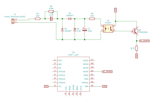
The MCU was unable to read the signal. I tried raising the emitter resistance in hope of raising the signal level, but I chose to change from 100 ohm to 220 ohms to no avail. So, confused, I removed the resistor and added a 3904 transistor in a Darlington configuration to increase the current and by increasing the current increasing the voltage at emitter. The emitter of the 3904 was connected to a digital pin in the MCU and tied it to ground via 1k resistor. This is only a workaround for now. I intend to eliminate this transistor in the future.
![Detecting circuit with ESP8266. Detecting circuit with ESP8266.]()
Detecting circuit with ESP8266. Testing this circuit with the same code we get quick and stable AC signal detection, without any bouncing. This solves the detection problem, now onto the next one: processing and publishing. But before that, we should test this circuit on an actual doorbell.
Part 2 - Communication
In my case, the doorbell was in an awkward position to reach in with a laptop, so I had to program in a sketch that will publish the number of times the mcu detected a signal via MQTT to my phone. This is the sketch I used: it’s a slightly modified example sketch of the popular Arduino PubSub library.
#include <Arduino.h>
#include <PubSubClient.h>
#include <ESP8266WiFi.h>

#define AC_SENSE_PIN 5

const char* ssid = "SSID";
const char* password = "hunter1";
const char* mqtt_server = "192.168.0.100";

WiFiClient espClient;
PubSubClient client(espClient);

void reconnect();
void setup_wifi();

void setup()
  {
    Serial.begin(115200);
    client.setServer(mqtt_server, 1883);
    pinMode(AC_SENSE_PIN, INPUT);
    setup_wifi();
  }

void loop()
  {
    static bool prev_state = 0;
    static int dingdong = 0;
    char dingdong_str[5];
    if (!client.connected())
      {
        reconnect();
      }
    if ((digitalRead(AC_SENSE_PIN) == 1)&& !prev_state)
      {
        prev_state = 1;
        Serial.println("DING!");
      }
    if ((digitalRead(AC_SENSE_PIN) != 1)&& prev_state)
      {
        prev_state = 0;
        dingdong++;
        sprintf(dingdong_str, "%d", dingdong);
        Serial.print("DONG! ");
        Serial.println(dingdong);
        client.publish("house/doorbell",dingdong_str);
      }
    yield();
    client.loop();
  }

void setup_wifi()
  {
    delay(10);
    Serial.println();
    Serial.print("Connecting to ");
    Serial.println(ssid);
    WiFi.begin(ssid, password);
    while (WiFi.status() != WL_CONNECTED)
      {
        yield();
        Serial.print(".");
      }
    Serial.println("");
    Serial.println("WiFi connected");
    Serial.println("IP address: ");
    Serial.println(WiFi.localIP());
    client.publish("house/doorbell/status", "ALIVE");
  }
void reconnect()
  {
    while (!client.connected())
      {
        Serial.print("Attempting MQTT connection...");
        char clientId[] = "Doorbell";
        if (client.connect(clientId))
          {
            Serial.println("connected");
          }
        else
          {
            Serial.print("failed, rc=");
            Serial.print(client.state());
            Serial.println(" try again in 5 seconds");
            delay(5000);
          }
      }
  }
To test this, I've setup a Mosquitto MQTT broker on a computer on my network. MQTT is a subject that warrants its own video. To keep it short and simple, MQTT is a way in which device broadcasts messages on specific topics to anybody listening that specific topic (also known as publishing and subscribing). MQTT requires a server or broker like Mosquitto to keep everything in order, so we need to install it on a computer.
After following the installation procedure of Mosquitto, we are ready to publish messages.
Testing the code on the same setup as before gave us positive results. The app I used on my tablet to read MQTT messages is called MQTT dash, available for android. I proceeded to install the circuit on my doorbell. First, I pulled the wires that were connected to the solenoid and attached some leads with some electrical tape. These feed directly to the mains side of my board. The mcu was powered with a phone charger because we haven’t defined how we are powering the board, yet. And as you can see, the board manages to send MQTT messages just fine.
Part 3 - Low Power Design
This leaves us with one last problem, low power design. This is probably the hardest part of the project and last piece of the puzzle because you need to consider everything.
Before we choose the battery, we need to define the power consumption and life. And the power consumption is defined after we define the operating principle of the sensor.
What’s the operating principle? Consider this.
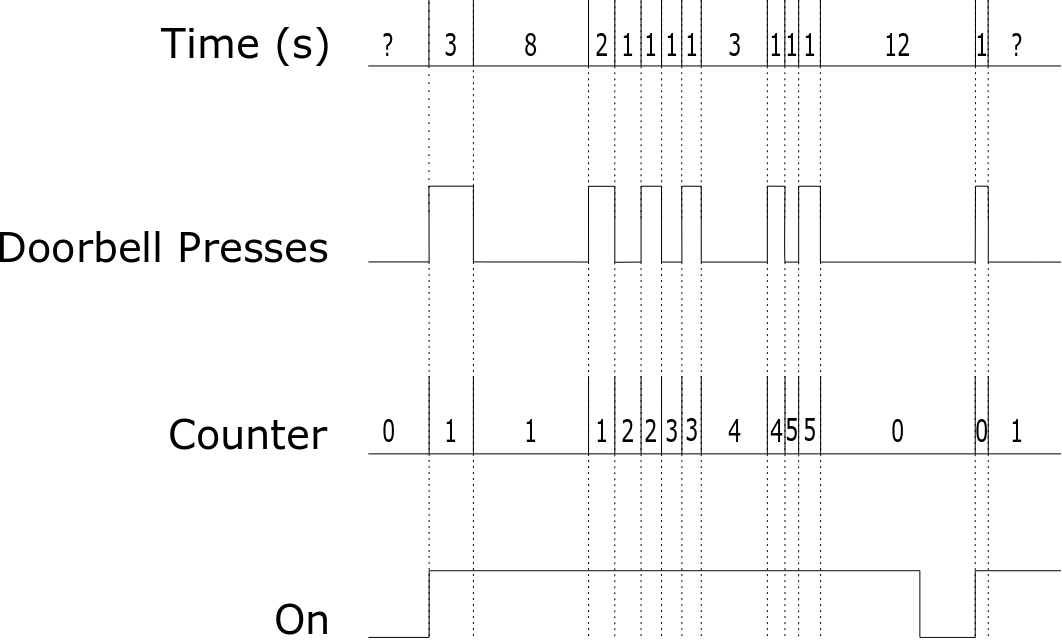
To maximize life, we need to force the sensor to sleep until there’s a ringing event. Where it wakes up and publish a message to the broker. Ringing events are counted if there is a big enough gap of time between button presses. So if a visitor walks to the door and press the button multiple times, pause for some time and press the button again, it should be recorded as 2 ringing events even if the visitor pressed the button more than 2 times.
Why is this important? It will completely define your battery life. Because if the sensor were to wake up, publish the message and enter sleep mode then it will miss the presses when cycling on and off. and if the sensor never sleeps then the battery life will be abysmal.
Let’s define the event time to be 10 seconds, when the bell rings, the device will wake up publish a message and stay on for 10 seconds. If there are more button presses within that 10 seconds the timer will restart. If the timer reaches the 10 second mark after the last button press, it will enter sleep mode.
![Operating principle of the sensor. Operating principle of the sensor.]()
Operating principle of the sensor. If we assumed 10 ringing events a day with a 10 second timer, then we get 100 seconds of operating time a day. Our microcontroller is the ESP8266. According to Espressif, the manufacturer of the MCU, the average power consumption is about 80mA which will equal to a current consumption of 2.2mAh @ 3.3v a day and an energy consumption of 7.3mWh/day. Per year is about 803mAh and 2650mWh.
To supply power to these devices we must choose a voltage regulator. Typically, you always choose between linear power supplies, where battery life can be estimated using the mAh rating or switching power supplies where the battery life is dependant on the Wh ratings.
As you may have noticed, we can’t even compare them without choosing an appropriate battery.
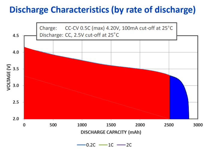
The best candidates so far are alkaline cells like AA or lithium cells. Linear regulators can only lower the voltage that means that they will work up until the battery voltage is close to the operating voltage. How close? Well for the LDO variant, it’s pretty close, in the range of the tens of millivolts. A single lithium cell will work just fine, the only problem is that a small part of the charge won’t be used up which is good for the health of the cell. How much energy are we leaving off? You can estimate it by looking at a discharge graph that plots the voltage of the cell over time at a fixed discharge current. Since the current is fixed then the variation in voltage is analogous to the variation in power and since its plotted against time then the area under the curve is analogous to the energy in the cell.
Intersecting the lowest current curve with 3.3v we can look at a representation of the state of charge of the cell, the area to the left indicates the energy used up once it reaches that voltage and the area to the right indicates the energy remaining in the cell.
![State of charge for lithium cells at 3.3V for the Panasonic NCR18650PF. State of charge for lithium cells at 3.3V for the Panasonic NCR18650PF.]()
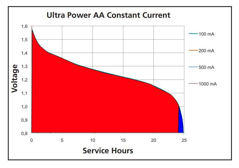
State of charge for lithium cells at 3.3V for the Panasonic NCR18650PF. For AA batteries is a similar story but because they are cheaper and quote unquote disposable, using 4 cells will guarantee that we use up almost all the energy in the cell since they are considered dead at 1v per cell, the dead voltage of the pack will be 4v and that’s above the regulated voltage.
![State of charge for Duracell MX1500 alkaline AA batteries at 1V. State of charge for Duracell MX1500 alkaline AA batteries at 1V.]()
State of charge for Duracell MX1500 alkaline AA batteries at 1V. Let’s now consider the sleep current.
According to Espressif, Deepsleep current can get a low as 20uA. However, that’s only the MCU we still need to consider the current draw of all other components in the circuit. The popular AMS1117 linear regulator have a quiescent current of 5mA which is unacceptable. Better linear regulators will draw around 1uA which we can neglect.
For switching PSU the story is different. Good ones have 15uA quiescent current which will almost double the current draw when sleeping which will now be 35uA. Not to mention that their efficiency is bad at those current draws. This is a win for the linear regulators, but I have an even better solution.
Both linear and switching PSUs have a built-in enable pin that will power on or off the regulator when toggled. The current draw of the regulator is still present but on the 10s of the nA range which we will grossly round up to 1uA, just to be extra safe.
Let’s call this mode hibernation mode. Since the PSU is off, the current draw from the mcu is 0. The only current draw come from the regulator and accessory circuitry. To be safe let’s assume is a safe 5uA for both regulators.
Now, how do we enter hibernation mode? Here is how.
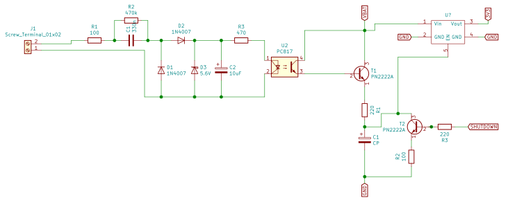
When the optocoupler gets a signal, T1 gets biased and C1 gets charged via T1 and R1. When the optocoupler is off, the charge is held and the voltage at t1’s emitter should be close to Vbat. The enable pin is connected to this node which turns on the regulator and MCU and stays turned on for 10 seconds processing any signal from the optocoupler. When the MCU is done, it activates t2 that will discharge the capacitor via r2. Once the voltage drops below logic high the MCU turns off and t2 deactivates.
![Hibernation circuit added to the schematic. Hibernation circuit added to the schematic.]()
Hibernation circuit added to the schematic. Now we are ready to decide and design our power supply! So far, we have to make 3 decisions: Lithium vs Alkaline, Linear vs Switching, Deepsleep vs Hibernation. That’s 8 scenarios! We can even be more meticulous, but that’s enough for now.
The actual daily consumption is 100s of 80mA @3.3v and 86300 seconds of deepsleep/hibernation. Running the numbers for each scenario yielded the following results:
NOTE: The values in the video were wrong, here are the corrected values. The idea is still the same.
![Consumption and battery estimated with the operating principle. Consumption and battery estimated with the operating principle.]()
Consumption and battery estimated with the operating principle. Which were not that surprising. The top 3 combinations were lithium/linear/hibernation with 1622 days or 4.44years, lithium/switching/hibernation 1546 days or 4.23 years and alkaline/switching/hibernation with 1517 days or 4.15 years.
Although it may seem counterintuitive to see linear regulators perform better than their switching counterparts, it makes sense. The efficiency of a linear regulator is mostly determined by the voltage difference between input and output. It can be calculated by dividing the voltage output by the voltage input and multiplying by 100%. For lithium, the efficiency was about 89% which was higher than the switching PSU efficiency at about 85%. For alkaline batteries, the efficiency of linear regulators was about 55% which is horrendous and way lower than the switching efficiency.
It will seem like a no brainer to go with the clear winner of this competition however a smarter pick would be the 3rd place and there are many reasons why:
First, price. A 4000 mAh lithium cell from a reliable source will run about 10-15 dollars compared to a common 4 AA battery pack that costs about 1-2 dollars or even less. Sure, you can recharge lithium every time they are discharged and at that rate your grandkids will have grandkids by the time you need to replace the cell. But think about it for a second, to justify a lithium cell at that price you need to burn through 28 alkaline batteries which will equal about 35 years. If you still think it’s worth it, let me go through my other reasons.
Second, self-discharge. According to battery university, lithium batteries like li-ion and lithium loses about 5% of their charge within the first 24 hours without doing anything. After that they lose another 4-5% each month. You won’t even make it to the 2-year mark before needing to recharge. Alkalines, on the other hand, loses about 2-3% each year.
And lastly my third point, recharging. Even if we ignore the self-discharge problem we just brought up, when the lithium discharges you still need to recharge it. This involves reaching the doorbell, removing the cover, unplugging the battery, set it to charge, wait a couple of minutes our hours, reach the doorbell yet again, plug the battery in and close the cover. Maybe I made it sound more like a chore than it actually is but compared to just swapping the alkaline batteries in a single go, it's clearly at a disadvantage.
Also, how would you or anyone else like my parents charge that battery? You need some sort of separate battery charger since embedding one doesn’t make sense because charging the doorbell would imply a disassembly of the circuit. Just ask yourself, are you building this for you or for someone else?
To summarize our power design. The board will contain a switch mode step-down (buck) power supply and it will be powered by 4 AA batteries. When inactive it will enter hibernation mode and we are expecting a battery life of just above 4 years.
Part 4 - The Prototype
The proper way to test this is using the actual chip we intend to use on our final version. But placing orders takes a while and without properly testing the hibernation circuitry, we shouldn’t assume it’s going to work.
On my parts bin I found a step-down switching power supply. Based on the Texas instrument LM2596. The module didn’t break out the enable pin, so I had to solder a jumper to it. Upon reading the datasheet, this PSU is way out of spec. The standby current is about 80uA, operating quiescent current is 5mA and efficiency is about 70%. This will yield a reduced battery life overall, but since this is a prototype, it wouldn’t matter anyway. The biggest difference and by far the worst offender is that the enable pin in the PSU is an active low, that means that in order to enter hibernation mode, the pin must be held high. The hibernation circuitry we tested earlier was designed to operate with an active high, but that’s ok because swapping the triggering pin with the shutdown pin should work. Except it doesn’t.
Not only is the enable pin working backwards, it sinks way too much current that our buffer capacitor gets discharged in less than a minute, dropping the enable pin to low which turns on the regulator. If the enable pin was active high, this bug would’ve worked as a feature since it will automatically turn off the regulator after some time if the ESP hanged and doesn’t turn itself off.
To fix this, I added a MOSFET configured as an inverting buffer. The capacitor gets connected to the gate of the MOSFET which ideally doesn’t draw current. When the capacitor is discharged, the current at the drain is 0 and the voltage at the drain is high. When the capacitor is charged, the gate-drain voltage is low then the voltage at the drain is also low. After testing this, the capacitor can hold its charge for way longer and if it discharges, it’s a fail-safe instead of a fail deadly.
One thing to note is that our hibernation current is about 45uA. This is lower than the 80uA the datasheet states, we are not complaining though.
Alas, we solved our final design problem. We can jump right into prototyping.
Testing was extensive. Many parts didn’t work as planned so I had to tweak, test and retest many aspects of the design. But after many trials and tribulations, the circuit worked as intended. The system woke from hibernation when the button was pressed, register every press without repeating and enter hibernation mode after 10 seconds of the last press.
At this stage, we can add and test many hardware features to augment the functionality of this project. The ones I’m planning to add are: battery level sensor, wake up and shutdown buttons and programing switch.
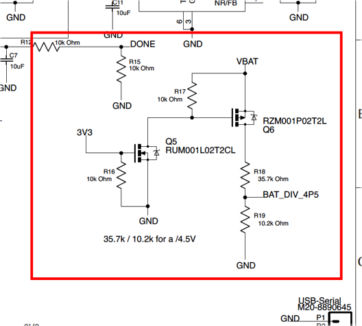
The battery level sensor will measure the voltage level of the battery using the analog pin on the MCU. For the esp8266, we need to add a few components to make this possible because it only reads from 0-1V and the battery will have maximum voltage of 6.5 probably even higher. The easiest way to achieve this is by implementing a voltage divider that will scale the voltage to a readable level. To get a division by 6.6 with common values we can use 5.6k and 1k ohm resistors.
This introduces a problem; voltage divider constantly draws current. Increasing the values might sound like a reasonable fix for this, however high resistor values are susceptible to noise. Adding a few MOSFETs to connect and disconnect the voltage divider solves this issue. This is the exact diagram Kevin Darrah, electronics engineer and youtuber, used on a similar project. (Side note: this project was hugely influenced by him, you should check out his channel, link in the description).
![Kevin Darrah's solution to low power battery level monitoring. Kevin Darrah's solution to low power battery level monitoring.]()
Kevin Darrah's solution to low power battery level monitoring. The other additions were pretty trivial, just a few buttons that simulates a button press and a shutdown signal. The programming switch is just a simple dip switch that the MCU will read as soon as it boots up to enter programming mode, disabling the shutdown signal. This enable us to program the MCU without the need to disconnect it from the circuit.
Testing these features went well. The voltage of the batteries was reported to a MQTT topic and monitored on my phone. The button did exactly what they were meant to do, and the switch was easily read by the MCU.
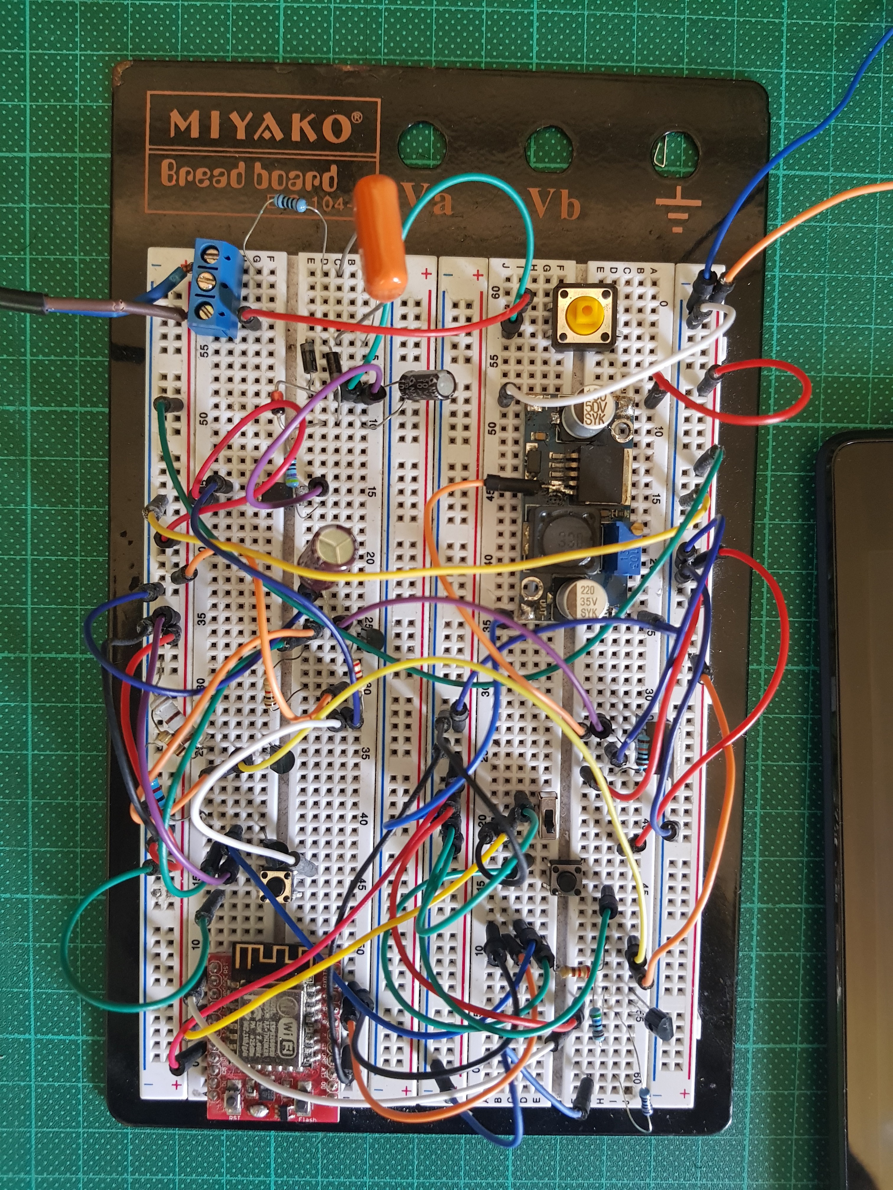
The breadboard prototype looked like this. Not exactly the nicest thing to look at.
![Breadboard prototype Breadboard prototype]()
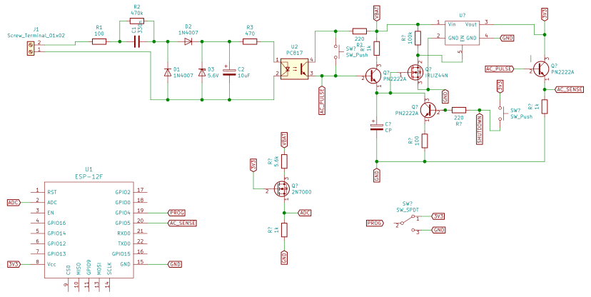
Breadboard prototype The schematic of the prototype is the following:
![Prototype schematic Prototype schematic]()
Prototype schematic This is the sketch I wrote for this test. It is rushed and nowhere near finished, it will get a huge overhaul soon.
#include <Arduino.h>
#include <PubSubClient.h>
#include <ESP8266WiFi.h>

#define AC_SENSE_PIN 5
#define SHUTDOWN_PIN 4
#define TIME_OUT 10000
#define ANALOG_PIN A0

const char* ssid = "SSID";
const char* password = "hunter2becausehunter1washacked";
const char* mqtt_server = "192.168.1.100";

WiFiClient espClient;
PubSubClient client(espClient);

void reconnect();
void setup_wifi();

void setup()
  {
    Serial.begin(115200);
    client.setServer(mqtt_server, 1883);
    pinMode(AC_SENSE_PIN, INPUT);
    pinMode(SHUTDOWN_PIN, OUTPUT);
    setup_wifi();
  }

void loop()
  {
    static bool prev_state = 0;
    static int dingdong = 0;
    static bool first_loop = 1;
    static unsigned long shutdown_time = 0;
    int adc_read;
    float bat_voltage;
    char dingdong_str[5];
    char bat_voltage_str[7];
    if (!client.connected())
      {
        reconnect();
      }
    if (first_loop)
      {
        adc_read = analogRead(A0);
        bat_voltage = (((float)adc_read)/1024)*6.6;
        dingdong++;
        sprintf(dingdong_str, "%d", dingdong);
        sprintf(bat_voltage_str, "%.2f", bat_voltage);
        Serial.print("DING DONG! ");
        Serial.println(dingdong);
        Serial.print("Battery voltage: ");
        Serial.print(adc_read);
        Serial.print(" ");
        Serial.print(bat_voltage);
        Serial.print(" ");
        Serial.println(bat_voltage_str);
        client.publish("house/doorbell",dingdong_str);
        client.publish("house/doorbell_voltage",bat_voltage_str);
        first_loop = 0;
        shutdown_time = millis() + TIME_OUT;
      }
    if ((digitalRead(AC_SENSE_PIN) == 1)&& !prev_state)
      {
        prev_state = 1;
        Serial.println("DING!");
      }
    if ((digitalRead(AC_SENSE_PIN) != 1)&& prev_state)
      {
        prev_state = 0;
        dingdong++;
        sprintf(dingdong_str, "%d", dingdong);
        Serial.print("DONG! ");
        Serial.println(dingdong);
        client.publish("house/doorbell",dingdong_str);
        shutdown_time = millis() + TIME_OUT;
      }
    yield();
    client.loop();
    if (millis() == shutdown_time)
      {
        Serial.println("Timed out, entering hibernation mode...");
        digitalWrite(SHUTDOWN_PIN, 1);
      }
  }

void setup_wifi()
  {
    delay(10);
    Serial.println();
    Serial.print("Connecting to ");
    Serial.println(ssid);
    WiFi.begin(ssid, password);
    while (WiFi.status() != WL_CONNECTED)
      {
        yield();
        Serial.print(".");
      }
    Serial.println("");
    Serial.println("WiFi connected");
    Serial.println("IP address: ");
    Serial.println(WiFi.localIP());
    client.publish("house/doorbell/status", "ALIVE");
  }
void reconnect()
  {
    while (!client.connected())
      {
        Serial.print("Attempting MQTT connection...");
        char clientId[] = "Doorbell";
        if (client.connect(clientId))
          {
            Serial.println("connected");
            // client.publish("home/doorbell", "hello world");
          }
        else
          {
            Serial.print("failed, rc=");
            Serial.print(client.state());
            Serial.println(" try again in 5 seconds");
            delay(5000);
          }
      }
  }
Time for another test, this time, the real test.
We prop up the circuit next to the doorbell, attach the leads we left connected from a previous test to the terminal blocks of the circuit power it up. As expected, everything worked perfectly. But that’s only testing short term, we need to test long term functionality.
It's very tempting to just leave the breadboard hanging from its wires or awkwardly anchored to the doorbell and start designing the PCB. I will work just fine, but the idea of leaving this somewhat heavy piece of metal hanging upside-down held only by focus commitment and sheer will makes me feel stressed.
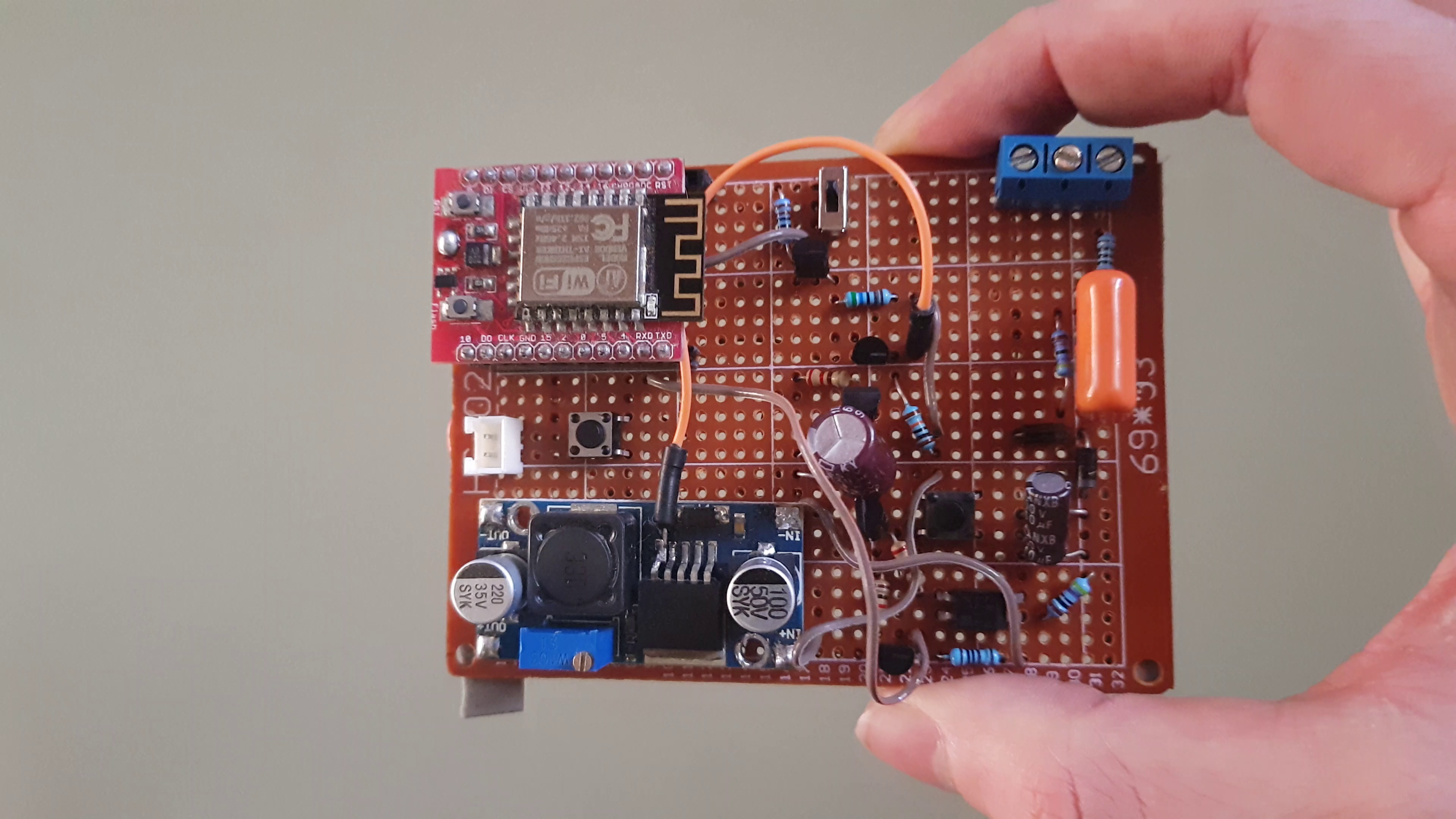
The obvious way to go around it is with Veroboard and soldering. Lots of soldering.
Not much to add here, the large number of parts speak for themselves. This will take some time and that heavily depends on your soldering skills. A few recommendations for beginners, use flux cored solder, don’t try to make it small, plan ahead, don't be afraid to use jumper wires and always solder with your favorite music.
![Veroboard prototype Veroboard prototype]()
Veroboard prototype After the Veroboard prototype is finished, the project is ready for the big test. So, I added some heavy-duty double-sided tape to the board and the battery, climbed my ladder, stick it to the doorbell enclosure and finish installing it the same way we did with the breadboard prototype.
A quick test with the buttons and the MCU wakes up and sleeps. Ringing the doorbell wakes the board up and it published a message and goes to sleep shortly after.
Let’s call it a success and the end of part 1. In the following episodes we will design and build the sign prototype, finalize the programing, revise the schematic, order and assemble some PCBs and make some enclosures.
See you soon!
WiFi-Enabled Visual Doorbell
A system that converts (non-destructively) a regular doorbell into a visual system with IoT features via WiFi.
 Octavio.Makes