-
1Parts
The only important module which is required with the rest being optional is the ESP32-CAM. Which you can find here.[ALIEXPRESS] { LCSC product page}
![]()
Moving on, I used a micro USB breakout board to supply power to the ESP32-CAM module which you can avoid by directly connecting the module to a power supply. For programming, you can use this module.
To get a better Wi-Fi range I added an antenna to the ESP32 module using the connector on the module which is again optional.
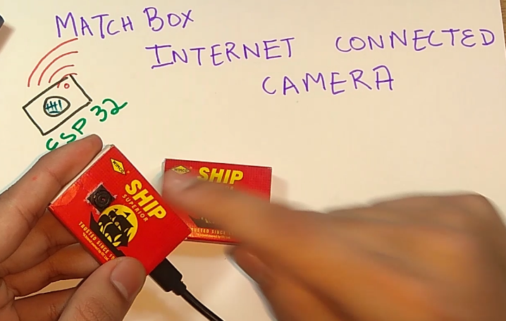
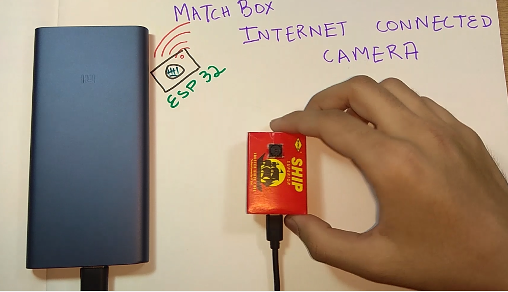
As a casing for the project, I used an old matchbox to show off its small size!
-
2Get the Project PCB Manufactured
You must check out JLCPCB for ordering PCBs online for cheap!
You get 10 good quality PCBs manufactured and shipped to your doorstep for 2$ and some shipping. You will also get a discount on shipping on your first order. To design your own PCB head over to easyEDA, once that is done upload your Gerber files onto JLCPCB to get them manufactured with good quality and quick turnaround time.
-
3Connections and Soldering
1. As there is no micro USB port on the ESP32-CAM module hence we add an external USB port using a breakout module for powering the project easily.
2. So I connected the +5V and GND lines of both the modules as shown in the hand-drawn diagram.
![]()
3. That's it for the connections! Test by powering up the module and you'll see the white led flash for less than a second.
-
4Put Your Camera in a Case
I used a matchbox and cut out holes for the camera and a slot for micro USB in the box using a paper cutter.
You can use any type of box or a 3D printed design or even you can use it without a casing and be hidden somewhere! Be creative while doing this.
-
5Download and Set Up the Arduino IDE
Download the Arduino IDE from here.
1. Install the Arduino IDE and open it.
2. Go to File > Preferences
3. Add https://dl.espressif.com/dl/package_esp32_index.json to the Additional Boards Manager URLs.
4. Go to Tools > Board > Boards Manager
5. Search for ESP32 and then install the board.
6. Restart the IDE.
-
6Playing With the Camera
Open a web browser in any phone or computer and head over to the IP as shown by the serial monitor.
If the serial monitor is not accessible for some reason you can use Angry IP scanner to see the IP of the camera.
![]()
As soon as you enter the IP on your browser you will be able to see a webpage which has different options to configure the camera which you can use.
Enjoy securing your candies with this camera!
-
7Coding the Module
Download the GitHub repository: https://github.com/akarsh98/arduino-esp32/tree/mas...
You need to connect the ESP32-CAM module with a USB to Serial as per the diagram is given and then connect the setup to your computer.
![]()
1. Open the sketch from GitHub in the Arduino IDE.
2. Navigate to Tools > Board. Select the appropriate board that you are using. ESP32 dev Module.
3. In partition select No OTA (large APP)
4. Select the correct comm. port by going to Tools > Port.
5. Connect the GPIO0 to GND and hit the reset button on the module.
6. Hit the upload button.
7. Disconnect the GPIO0 with the GND and hit the reset button.
8. When the tab says Done Uploading you can open the serial monitor to see the IP at which the camera will stream.
Wireless Security Camera in a Matchbox
An internet-connected camera which has wifi on board and is so small that it fits in a matchbox, for securing your valuables.


Discussions
Become a Hackaday.io Member
Create an account to leave a comment. Already have an account? Log In.