Andrey Skvortsov
-
Sleep Well and Wake Up On-time!
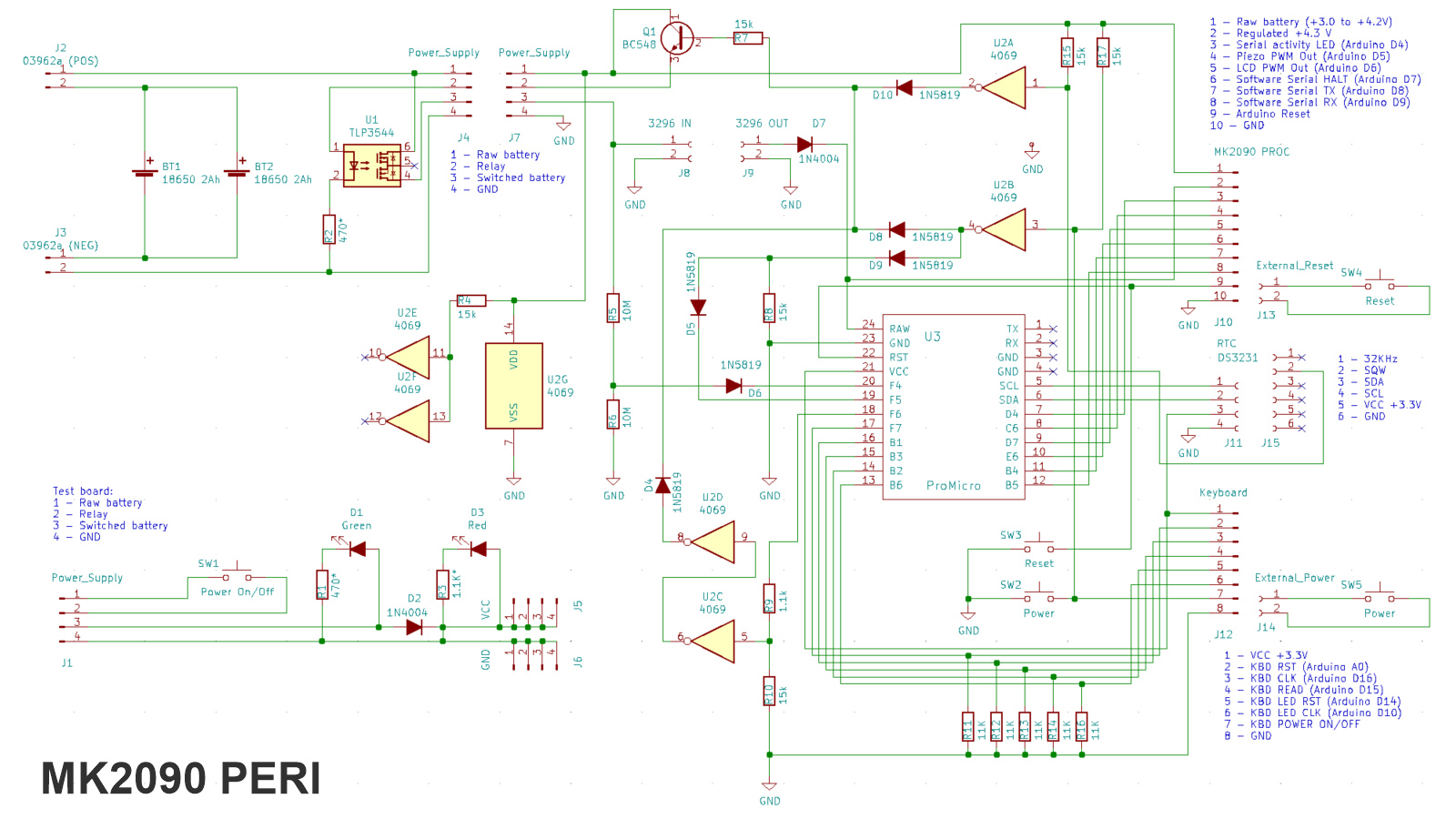
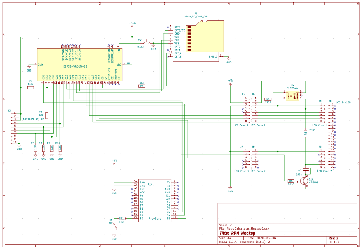
12/02/2020 at 05:48 • 0 commentsLast two weeks I spent on hardware development. According to the requirements, the calculator should be able to keep precise time in DS3231 Real-Time Clock (RTC) and wake up from deep sleep at the predefined moment. The final schematics looks as following:
![]()
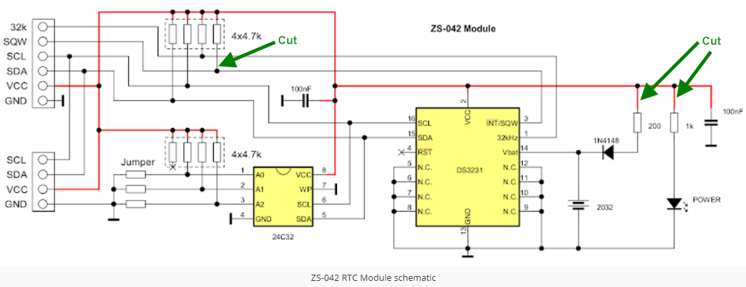
The wake-up signal is taken from the DS3231 SQW pin and send into a NOT element of 4069. The DS3231 is obtained in form of ZS042 breakout board - it is easier than soldering a surface mounted chip with many pins. The modifications on the ZS042:
(1) Mandatory - cut the top right leg of 4.7k 4-resistor assembly 1 - without it, the DS3231 will be able to keep the line up if VCC is off. Note that pin 3 (INT/SQW) is simply a MOSFET to GND - essentially an equivalent of a momentary switch to ground.
(2) Mandatory - remove 200 Ohm resistor in the battery charging circuit. Because the board is powered by VCC=3.3V, it is useless anyway, but may be a battery hazard if using with 5V supply.
(3) Optional - remove 1k resistor in the power LED (this reduces power consumption from 1.9 to 0.3-0.5 mA).
![]()
The chip programming magic is done earlier by Mike Yakimov - the author of https://github.com/myak555/Not_So_Tiny_Not_So_Basic - and available at https://github.com/ptravnik/Retro_CALC/tree/master/MK2090_Peripheral_Controller#include <Arduino.h> #include <Wire.h> #include "RTCData.hpp" //I2C Slave Address #define DS3231_SLAVE_ADDRESS 0x68 // Default control - battery oscillator ON and Alarm 1 DISABLED #define DS3231_CONTROL_DEF 0x04 // Default control - battery oscillator ON and Alarm 1 ENABLED #define DS3231_CONTROL_ALR 0x05 // Default status - all clear #define DS3231_STATUS_DEF 0x00 class DS3231_Controller{ public: bool firstRun = true; uint8_t lastError = 0; uint8_t wakeupStatus = 0; void begin(); bool isRunning(); void setDateTime( DS3231_DateTime datetime); DS3231_DateTime getDateTime(); DS3231_Temperature getTemperature(); void setWakeUp(DS3231_Alarm alr); DS3231_Alarm getWakeUp(); private: uint8_t _getRegister(uint8_t address, uint8_t n=1, uint8_t *data=NULL); uint8_t _setRegister(uint8_t address, uint8_t n, uint8_t *data=NULL); }; -
Sleep Well!
11/12/2020 at 05:30 • 0 commentsNow it was time to move to the power supply and the power management proper.
It has been discovered that none of the cheaper ESP32 boards have sleep power below 150 uA (see the excellent video with Andrew "Guy-With-The-Swiss-Accent" Spiess). The two boards I've tested personally - ESP Dev Module 1 and LoLin - both have the deep sleep power at about 3 mA (3.7 V connected to Raw).
Neither board has the battery discharge protection. The Lolin is capable of charging a LiPo cell, but the current for two 18650 seems insufficient. Neither board has the battery protection in case the voltage drops below 3.0V, so a separate battery main switch is needed. If you forgot to turn it off... well, the cells will be dead.
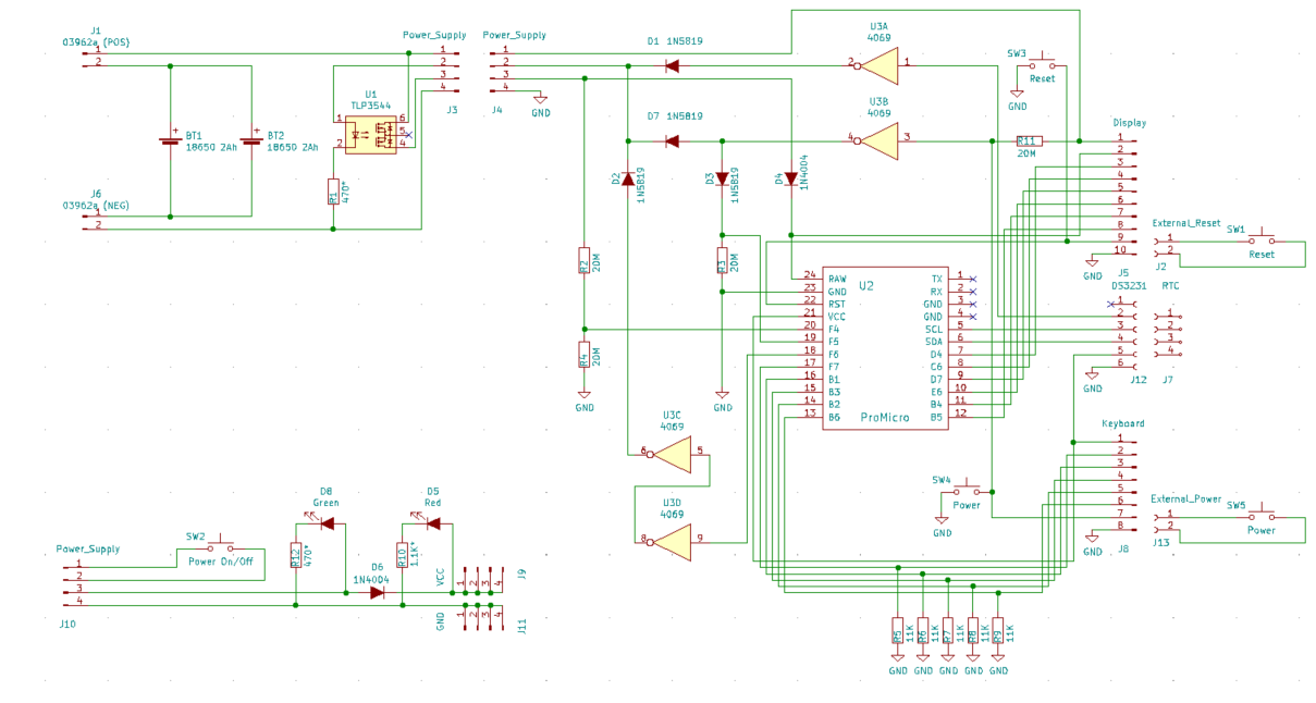
So came the proposed schematics.
- Two 18650 LiPo's are "balanced" and connected in parallell.
- The cells are charged and discharged with the 03962a 1A controller ($0.36 on Aliexpress). The controller regulates the battery charge current and also protects the battery from overdranage.
- On the discharge side, the output is controlled by the solid-state relay TLP3544 - if the pin 2 on J3 is pulled high, the relay opens, providing current on the pin 3. The pin draws about 5.7 mA if no additional resistance.
- On the Arduino side, the solid state relay is controlled by a single CD4096UBC chip and three signal diodes 1N5819, which is essentially a logical OR (no need for a chip here).
- The three inputs are: the power push-button SW4 (pressed = LOW); the SQW signal from real-time clock module DS3231 (alarm gone off = LOW) and the A1 output of Arduino Micro Pro.
The logic is as following:
- The system is initially OFF. The relay U1 is open, U2 (Arduino) is de-energized. The only power consumer is the U3 (CD4096UBC) chip, drawing about 8 uA via 0362a controller. At this state, the system may be connected to a charger through the dedicated USB port of the 0362a.
- User presses SW4 (or SW5). U3 closes the relay U1, sending power to Arduino U2, which performs its boot sequence. One of the first actions of Arduino is to declare port A1 as a digital output and set it HIGH.
- The high signal from A1 causes U3 via diode D2 to lock the relay U1 in "on" position. If the user releases the power button SW4, the system remains energized. Arduino can check the battery voltage by the port A3, configured for an analog input.
- If the user presses the SW4 again, the high signal via diode D2 reaches Arduino port A2, configured as a digital input. At this point, Arduino passes the signal to ESP32, which decides if the shutdown is needed (it may decide to ignore the user, for example if a program is running).
- Upon completing the neccesary shutdown sequence, ESP32 commands Arduino to shut-down. Arduino sets A1 to LOW, causing the relay U1 to disconnect. The only remaining power consumer is U3, and the rest of the system is totally off at the source.
If the Arduno program gets locked for some reason, the user can press reset button SW3 (or the optional external SW1). During the reset, the pin A2 momentarily goes low, which causes U3 to disconnect, - and the entire system is off.
If the system is powered via Arduino or ESP32 USB, the power board is protected by diode D4. Pressing the power switch has no effect - the system stays on. The system can be independently charged through 0362a. If the user pulls the USB plug off while the system is on, the power supply should pick up gracefully (not tested yet).
If the system is off, and DS3231 alarm goes off, the effect is the same as if the user presses the power button, only the signal is coming via diode D7 instead of D1. Note that the RT clock has its own small lithium cell.
If the system is on, and DS3231 alarm goes off, the system remains energized.
The power up and shutdown code is as following:
#include <Arduino.h> class SelfShutdown{ public: void init( uint8_t PortKey, uint8_t PortHold); inline bool isPowerPressed(){ return digitalRead(_portKey) == HIGH;}; void shutdown(); private: uint8_t _portKey = 3; uint8_t _portHold = 4; }; // // Power button is at PortKey and goes high if pressed // Solid state relay is attached to PortHold, if held high, battery power is connected // void SelfShutdown::init( uint8_t PortKey, uint8_t PortHold){ uint8_t _portKey = PortKey; uint8_t _portHold = PortHold; pinMode( _portHold, OUTPUT); digitalWrite( _portHold, HIGH); // Lock yourself in power-on pinMode( _portKey, INPUT); delay(30); while( digitalRead(_portKey) == HIGH) delay(30); // suppress power button jitter } void SelfShutdown::shutdown(){ digitalWrite(_portHold, LOW); delay(500); digitalWrite(_portHold, HIGH); // if at this point we are still alive, must be USB power... } -
Calculator Gets New Keyboard
07/13/2020 at 00:03 • 0 commentsThe final keyboard version has been completed. The only remaining task is to design and laser-cut the top cover.
![]()
-
A Ton of Functions
06/15/2020 at 10:19 • 1 commentOver 70 application functions have been implemented so far.
The full list is here.
For instance, if you want to compute an average, it is easier than on HP-35s!
Common Experiment Processing
Given: In the dance class of 10 students, the heights were measured at 147, 152, 165, 163, 168, 163, 175, 166, 170, and 167 cm.Find: The mean height and its standard deviation in the class.
- Type
clear sum,<Enter>(a shortcut is<F1>,<A>, which displaysclear) - Type
sum 147,<Enter> - Type
sum 152,<Enter> - Continue for the other 8 numbers. Instead of typing sum, you also can type a number and press
<F1>,<S> - After each number the calculator displays number of samples, the mean and standard deviation.
After entering all 10 numbers, the display shows:
N____________________10
StDev________ 8.30261003
Mean______________163.6
Sum updated____________
>_
Answer: the average height of the class student is 164 cm (68% of samples are in the interval of 164±9 cm).
Normal Distribution and Probability
Given: In the dance class as above, assume normal distribution and fair representation of the school population.
Find: (1) Probability the next class participant is taller than 175 cm. (2) Interval of heights for 95% of the school population.
- Type
prob(175),<Enter> - The calculator displays: 0.91513344. This is the probability the next participant is under 175 cm.
- To find the answer, type
1,<Enter>,<Arrow Down>,<->. The calculator displays: 8.48665622e-002. - Type
1,<Enter>,0.95,<->,2,/,probit,<Enter>. - The calculator displays: 147.3(...) This is the lower value.
- Type
probit( 0.975),<Enter>. - The calculator displays: 179.9(...) This is the upper value.
Answer: (1) the probability to find a student taller than 175 cm is 8.5% . (2) In the school, 95% of the students are in the interval between 147.3 and 179.9 (or 163.6±16.3) cm in height.
- Type
-
Variables, Files and Instant ON
05/24/2020 at 12:32 • 0 commentsAfter some major brain surgery, the RPN calculator understands BASIC variables
Variables' implementation
In the calculator, variable names may start with a letter or an underscore (
_) and can further contain letters and numbers, such as:My_variable,_my_other_variable,_my_other_variable2,Catch_22.As in the standard BASIC, the variable type is defined by name ending.
- The name with no ending is a 64-bit double-precision Real:
The_Ultimate_Answer = 42. - The name ending with
%is a 64-bit sighed Integer:The_Ultimate_Answer% = 42. - The name ending with
$is a string:The_Ultimate_Answer$ = "42". - The above three definitions are treated as different variables and co-exist in the memory.
- Some versions of BASIC also support variables of different precision, e.g.
a!designates a double-precision real. For the Calculator BASIC, these additional types are not yet implemented, and probably will not be - most of the time engineering calculations require double precision anyway.
BASIC supports 4 variable arrangements:
- Real or Integer numbers (scalars), e.g.
pi = 3.1415926. - Real or Integer vectors, e.g.
Fibonacci%[0] = 0 : Fibonacci%[1] = 1 : Fibonacci%[2] = 1. - Real or Integer matrices, e.g.
ROT[0,0] = cos(a) : ROT[1,1] = cos(a) : ROT[1,0] = -sin(a) : ROT[0,1] = sin(a). - Strings, e.g.
The_Ultimate_Answer$ != "42"evaluates to FALSE,The_Ultimate_Answer$[0]evaluates to "4".
Standard variables and Instant On
The following variables are always available (in the final version will be more):
- stack[i] - the RPN stack. The index i can be from 0 to 19; 0-X, 1-Y, 2-Z. The default value is 0.
- prev - the RPN previous value. The default value is 0.
- amode - the angle mode - 0 - degrees, 1 - radians, 2 - gradians. The default value is 0.
- current_dir$ - the current directory. The default value is "/" (root).
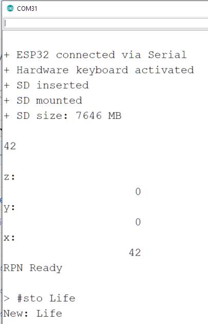
- scrMessage$ - the current message displayed in the box. The default value is "RPN Ready".
- rpnLabelX$ - the current message displayed above the X-register value in the RPN interface. The default value is "X".
- rpnLabelY$ - the current message displayed above the Y-register value in the RPN interface. The default value is "Y".
- rpnLabelZ$ - the current message displayed above the Z-register value in the RPN interface. The default value is "Z".
If the SD card is inserted, during a power-down all standard and user-defined variables are stored on the card in the file named /_RPN_SaveStatus.bin Upon the power-up, the calculator is automatically restored to the state just before the power-down. If the card is not present during power-down, all user-defined variables and other settings are lost. Upon the power-up, only the standard variables will be present and will be initialized with defaults.
This allows keeping separate working environments on different SD cards. Or, in some cases, it is important to have no stored environments on the calculator - for example, for math exams.
Implementation details
The current variable space is defined in Variables.hpp as VARIABLE_SPACE = 32000 bytes.
Variables are placed in the variable space as following:
- byte 0 - variable type (0-undefined, 1-number, 2-vector, 3-matrix, 4-string)
- byte 1 - variable name length (N). The name cannot be longer than 254 bytes.
- bytes 2 to N+2 - variable name (null-terminated)
Then:
- byte N+3 - either an 8-byte double or an 8-byte integer
Or:
- byte N+3 - total vector/string length as a 2-byte unsigned integer (L)
- bytes N+5 and above - either a null-terminated string or a vector of 8-byte numbers
Or:
- byte N+3 - total matrix length as a 2-byte unsigned integer
- byte N+5 - row length as a 2-byte unsigned integer
- byte N+7 and above - a matrix of numbers composed by row
![]()
- The name with no ending is a 64-bit double-precision Real:
-
Short Video Update
04/23/2020 at 08:05 • 0 commentsQuick-and-dirty video for the current project status:
-
Keyboard final, Serial connectivity, Wiki docs
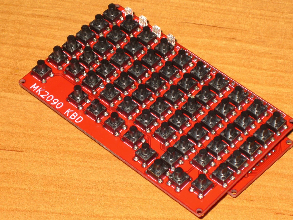
04/19/2020 at 08:19 • 1 commentFinally the keyboard PCBs have arrived from China.
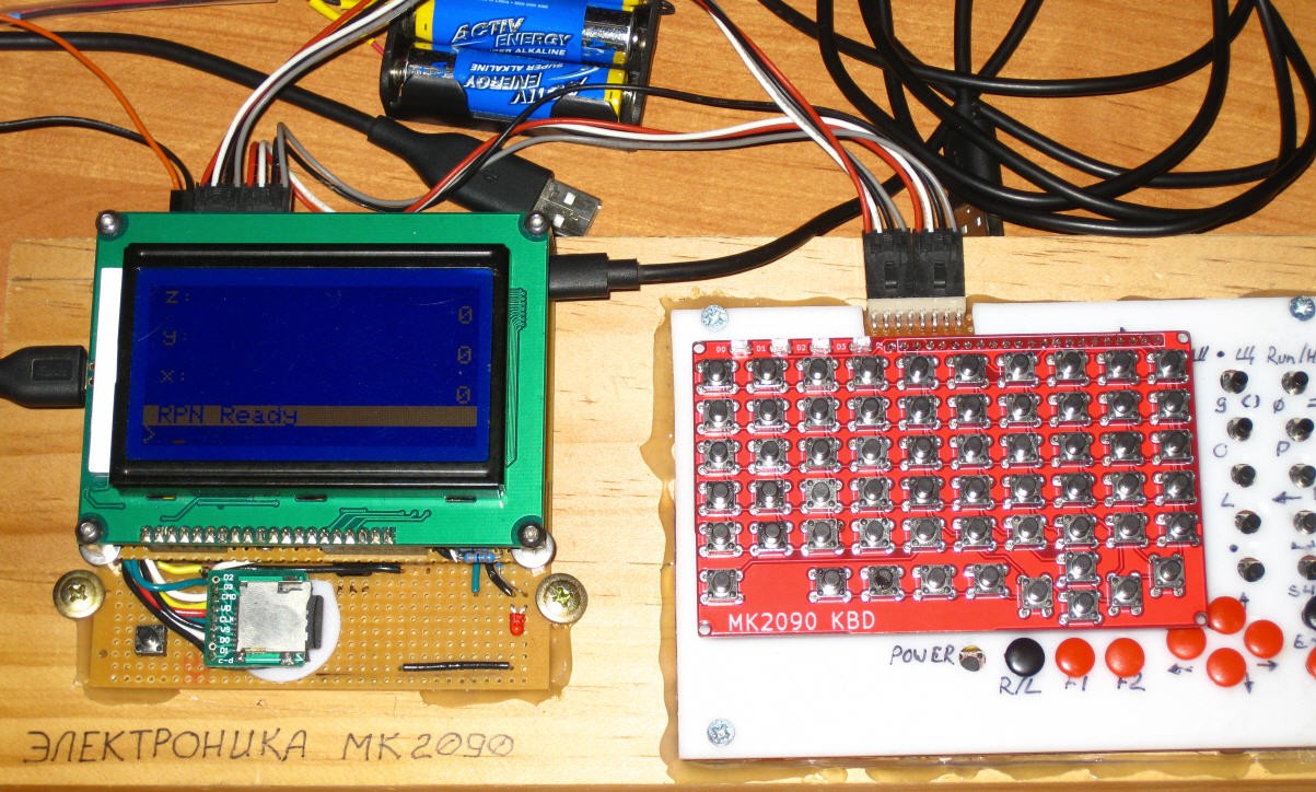
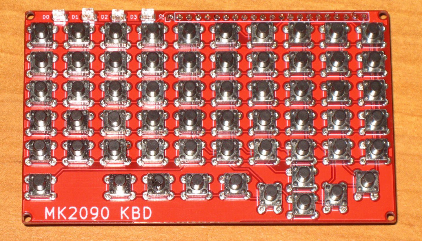
For the keyboard, it is the final design. The size is 60x100 mm, and the intended position is to the right from the screen:
![]()
(The screen itself is still in the mock up stage). The keyboard has 4 LEDs and 60 switches - the one on the bottom left is a hardware power switch. All LEDs and keys can be accessed independently - in theory all 59 switches can be closed at the same time and will register.
![]()
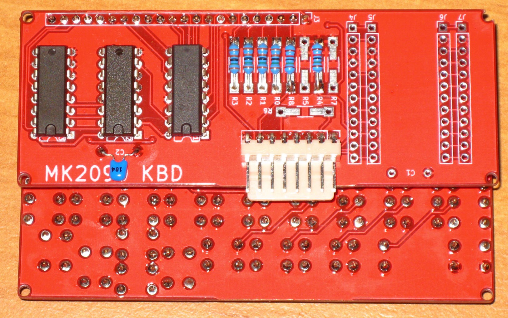
The keyboard driver board sits below. A header for Arduino Micro Pro is provided, in case the keyboard is used as a standalone unit for PC.
![]()
Currently the driver board and the keyboard are connected by a header; the production version will be soldered.
![]()
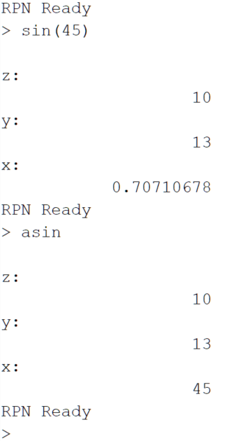
The RPN calc can now impersonate a keyboard and a 3-button mouse, injecting keystrokes into a PC. Mouse pointer movements and mouse wheel from the calculator to the PC are also supported. With a dumb terminal, the RPN understands both the RPN and an Algebraic inputs:
![]()
The documentation is started at the project Wiki: https://github.com/ptravnik/Retro_CALC/wiki
Next: programming a File Manager!
-
Hardware Mock-up Programmed
03/07/2020 at 07:49 • 0 commentsI have continued debugging the hardware mock-up. The fundamental target was to program a simple RPN calculator UI with 6 operations plus a number of scientific functions. The integration with BASIC will come later, after all the hardware components are finalized.
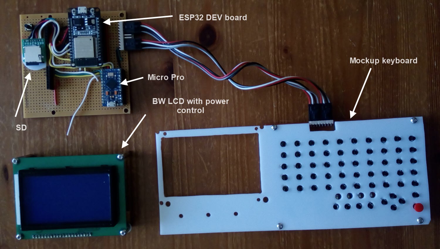
New Pro Micro clones with 3.3V processors have arrived, so the logic level conversion is no longer necessary. See the new wiring diagram in the file section.
![]()
Files are uploaded to https://github.com/ptravnik/Retro_CALC (its a proof-of-concept code, use with caution!)
Two problems have been hit so far. Firstly, the real-time clock of ESP32 is not very precise in the sleep mode; thus an external RT clock module is required in the future. Secondly, the sleep current of this particular Dev board is 15 mA, while in running (no WiFi) - 55 mA. Need to troubleshoot it a bit further.
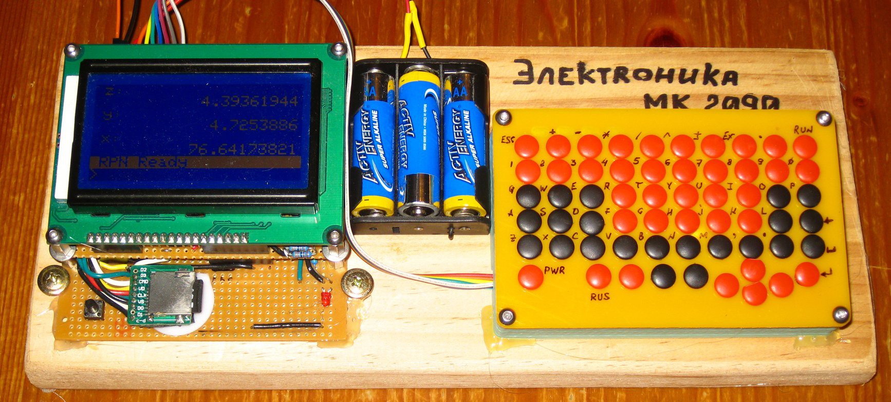
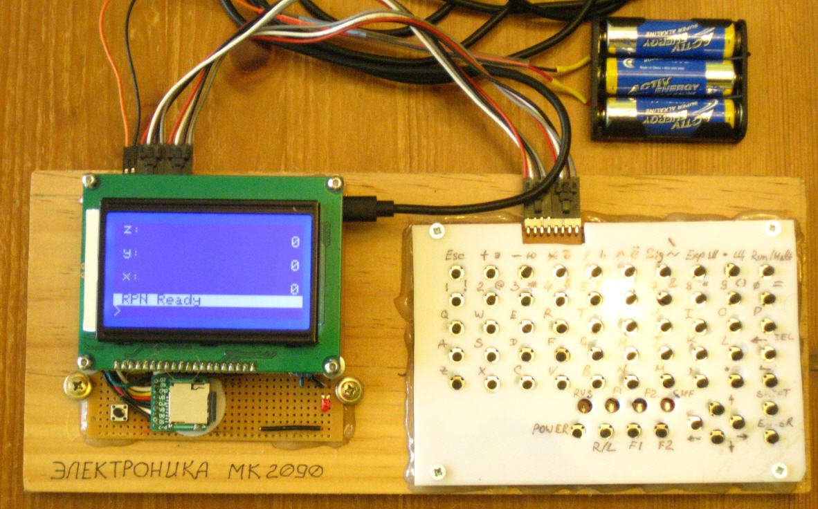
Currently the mockup looks a bit neater and can run from standalone power. Can you take it to the math exam?
![]()
The current functionality fully operational and tested:
(1) Hardware keyboard (a mock-up so far), with CP1251 code page support;
(2) LCD power manager, with PWM control and sleep capability;
(3) LCD driver with fancy LCD font, resembling Electronika MK-90;
(4) Sleep mode and wake-up by a hardware button;
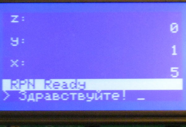
(5) RPN calculator UI.The font looks like this:
![]()
Or in Russian:
![]()
The current functionality implemented, but not fully tested:(6) Serial connectivity to Arduino Micro Pro;
(7) SD card reader.The deferred / not yet implemented functionality:
(8) Beeper;
(9) LiPo charger / battery;
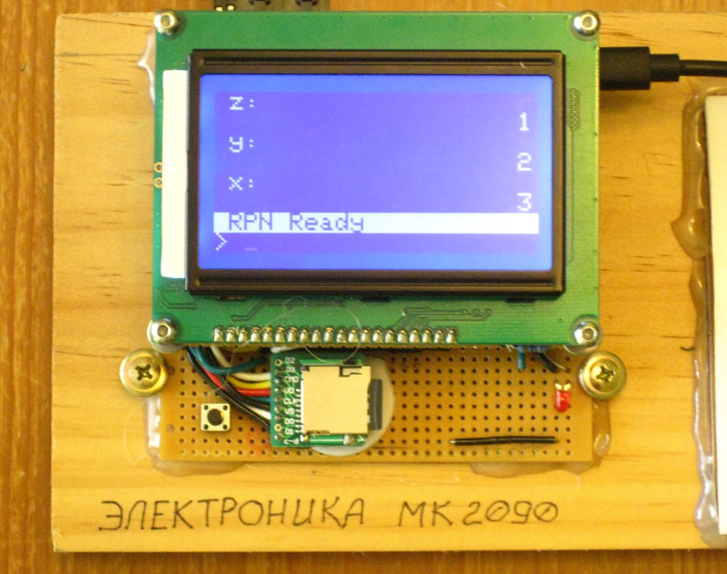
(10) Independent RT clock.The hardware is running a simple RPN calculator interface. The operation is as following:
o The calculator can be operated by either the hardware keyboard or a serial port terminal.
o The display is composed of 2 parts: the upper depicts the RPN stack, the lower is for entering commands.
![]()
o Enter numbers as normal, e.g. 123, 123.456, 123.456e89, 123.456e-89 etc. "E7" or "e7" stand for "10 power 7". Buttons <DEL>, <Backspace>, <Home>, <End>, <Left>, and <Right> should work as expected.
o Besides the entry as above, the following is allowed: 123k, 123M, 123c, etc. The letter is an "engineering multiplier": f="e-15", p="e-12", n="e-9", u="e-6", m="e-3", c="e-2", d="e-1", k="e+3", M="e+6", G="e+9", T="e+12", and P="e+15".o Upon entering a number, press <Enter>. If the number in the entry line is valid, it is processed into the X-register, if not - ignored. Upon entering the number in stack, all the values shift by one position. The current stack is 20 numbers.
o Alternatively, press an operation button <+>, <->, <*>, </>, <^>, or <+/->. If the number in the entry line is valid, it is processed into the X-register, if not - ignored. Upon this, an RPN operation on stack is performed. Division by 0 causes an error, which can be cleared by pressing <ESC>.
o The available math functions: sin, cos, tan,
sqrt - square root,
sq - square,
exp - e power x
sign,
inv - computes 1/x
hex - converts x to hexadecimal (rounds to integer first)
o Stack manipulation functions:
prev - previous X (shortcut: PGUP),
swap (shortcut: DOWN),
push, pop,
roll (shortcut: PGDN)
previous entry (shortcut: UP)
#scr status - updates status label
#scr labelx - updates label X
#scr labely - updates label Y
#scr labelz - updates label Z
o Screen power and brightness:
#scr off - puts screen to sleep
#scr on - wakes up screen
#scr+ - increase brightness
#scr- - decrease brightness -
Matrix operations with double precision
02/09/2020 at 20:49 • 0 commentsCan your next DIY programmable calculator do the same? :) This is Arduino DUE, hope ESP32 and even ESP8266 will be ready soon.
-
ESP32 Mockup Completed
01/15/2020 at 02:22 • 3 commentsFinally got the working mockup running. Currently the hardware includes:
- ESP32 dev module
- Arduino Micro Pro
- SD card reader
- BW LCD with a software LED control
- Hardware keyboard (a working mockup so far; the Chinese PCB manufacturer entered wrong delivery address, so the parcel is back to China)
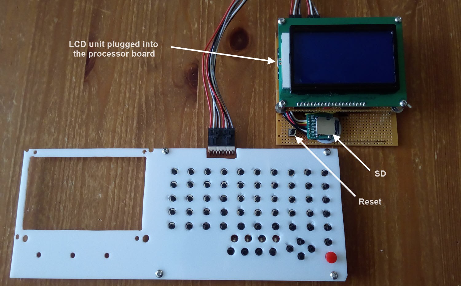
![]()
The LCD part can be easily removed from the primary board - it is held attached by a header.
![]()
Power consumption in this configuration:
- Input at 4.96V (WiFi, BT off in all tests)
- The LCD screen LED is fully on (75 Ohm resistor) 103 mA
- The LCD screen LED is fully off (but the LCD is running) 98 mA
- The LCD screen is off (ESP32 and Micro Pro running) 94 mA
- The LCD screen is off, Micro Pro off (ESP32 running) 82 mA
- The total power is wherefore 500 mW, and two 5000 mAh batteries will last 2*5*3.7/0.5 = over 3 days of continuous operation.
I have also compared this to the power consumption of Arduino Mega 2560 with a TFT 480x320 color screen and an SD card (see the video in the Project Log 01). Two different Mega we used: "Classic" and "OSEPP" (in brackets).
- Input at 4.96 V (BASIC is running)
- With TFT connected: 108 (118) mA, 550 mW - this is comparable to the BW LCD system, but no keyboard injection capability.
- With TFT removed : 22(32) mA, 125 mW.
I could not find an elegant way of disconnecting/managing the TFT power and the TFT backlight as it is mounted on a shield.
Obviously, Mega with a BW LCD would make a decent calculator with about 30-50 mA consumption, which equates to one month of a continuous running! Unfortunately, this system has only 4-byte arithmetic, no real-time clock, no WiFi, etc.
The calculator connects to the PC in three ways:
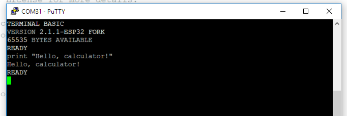
- Via ESP32 USB - for programming ESP32 and direct operation of Terminal BASIC via VT100
- Via Arduino Micro USB - for programming Arduino and impersonating a wired keyboard (still writing code for this - should be an INJECT keyword in BASIC)
- Via BT or WIFI of ESP32 - have not tested software yet, but the hardware is OK - BASIC now has a SET WIFI_NAME, SET WIFI_PASSWORD, NETTIME() keywords, and so you can set time from the network or make a table clock in BASIC.
The Terminal BASIC on ESP32 is working... kind of. I have replaced the capitalized keywords with a lower-case.
![]()
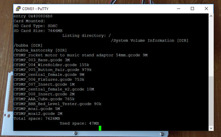
The SD card code is not compiling properly as the ESP32 and the Arduino libraries are different - still working on it. The hardware is fully operational, and I am able to run independent tests:
![]()
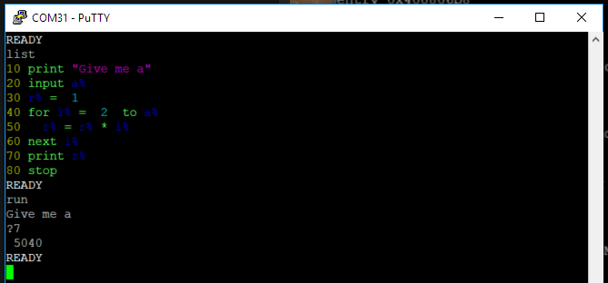
The Terminal BASIC is seemingly having a hard time working with double-precision numbers on ESP32. This program calculates a factorial in integers:
![]()
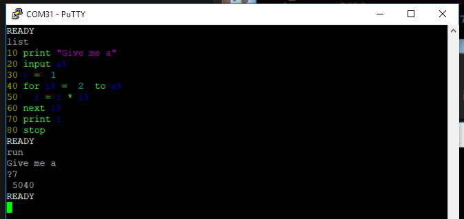
Now replacing r% with r - for 4-byte floats:
![]()
Finally, we replace "r" with "r!" ("!" stands for long reals) results in busted stack!
Next: debugging Terminal BASIC on ESP32!
Terminal-BASIC programmable calculator
A poket-to-laptop size microcomputer/programmable calculator, based on Terminal-BASIC