-
1Make holes in the garage wall
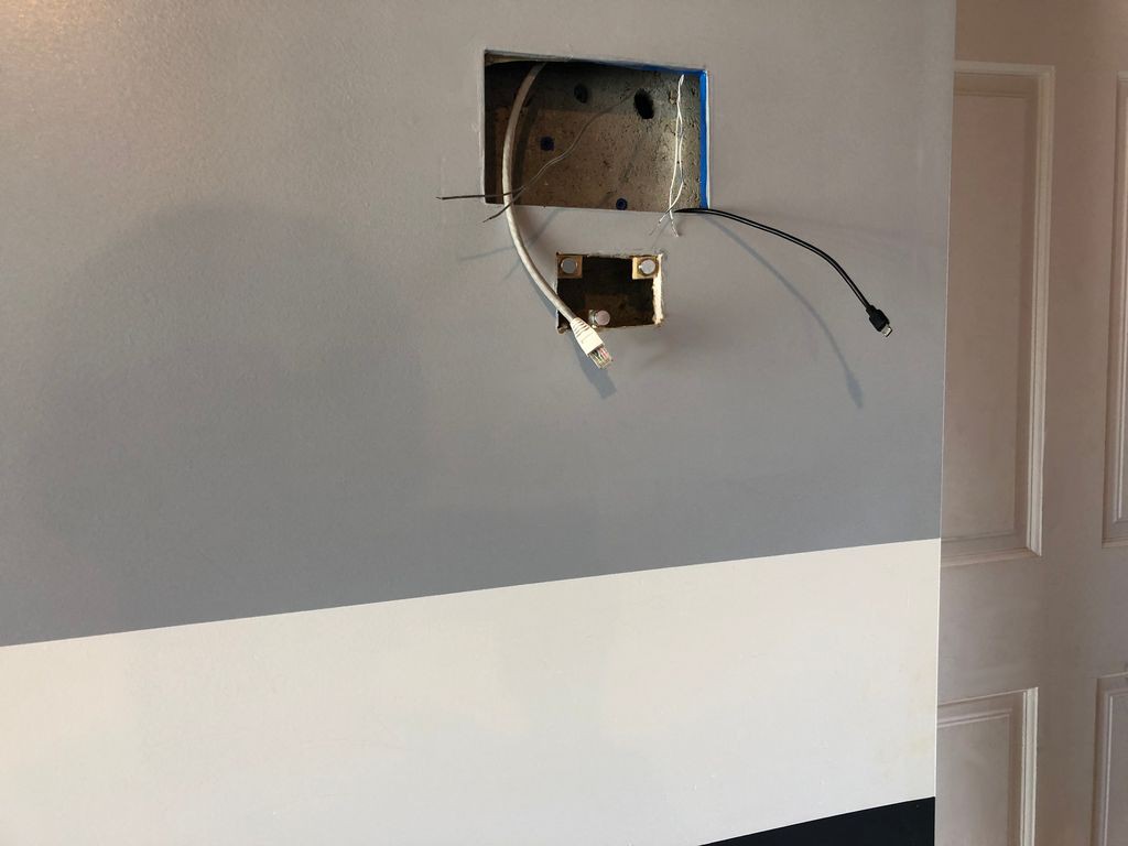
Make two holes in the garage wall, one for display, and other for racing car ignition switch.
It is the most important step, because after that there is no way back, you will finish the project :)
Also, I put micro USB power supply 5V / 3000mA behind thiis wall and send Ethernet cable. I prefer not to use wi-fi for smart things if possible, but it doesn't really important.
In my installation display with RPi sits fine because of it's own weight and wires, so there is no need to secure it additionally, but for ignition switch I used neodymium magnets. I guess you can do the same for display if needed
-
2Put together Display, RPi and Relay Shield
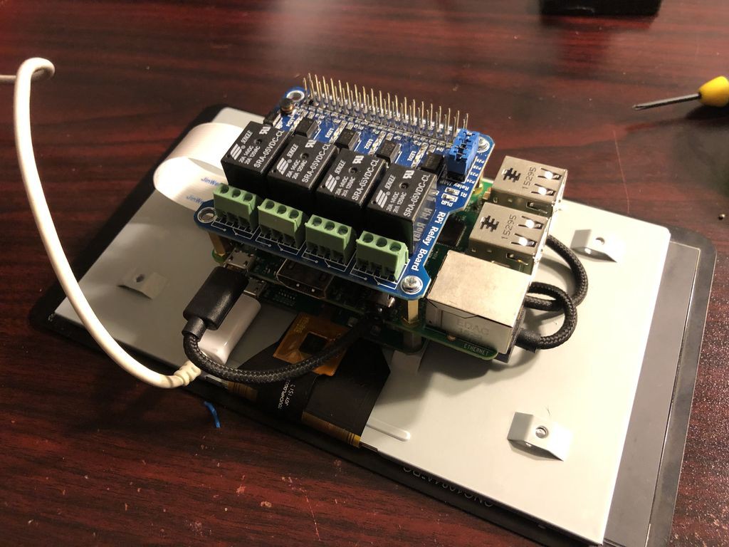
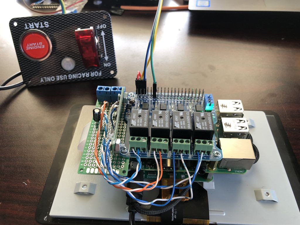
That's easy enough, stack RPi on top of display, manual has wiring instructions. After that, put relay shield on top.
If relay shield doesn't have standoffs included, I used these: Standoffs for Raspberry Pi M2.5 x 11mm + 5mm Brass Hexagon
As a result you will get nice 3 layers cake, like this one:
-
3Frankenstein
Now, how do we control garage doors? Older garage doors was simple, they have 2 wire system. Connect 2 wires, and garage door is started opening. or closing. Connect wires thru capacitor, and light goes on or off.
New garage doors have something called Security+ 2.0. Still 2 wires, but connecting them doesn't work any more. Not sure what it has to do with security, since it is wired connection anyway, but now on wall garage opener button will cost you $7 at minimum.
I have 2 garage doors, one is old, other is Security+ 2.0, so I'll show you how to deal with both. Obviously you can come up with your own Frankenstein, by soldering into garage door opener remote for example.
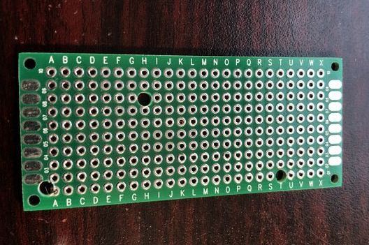
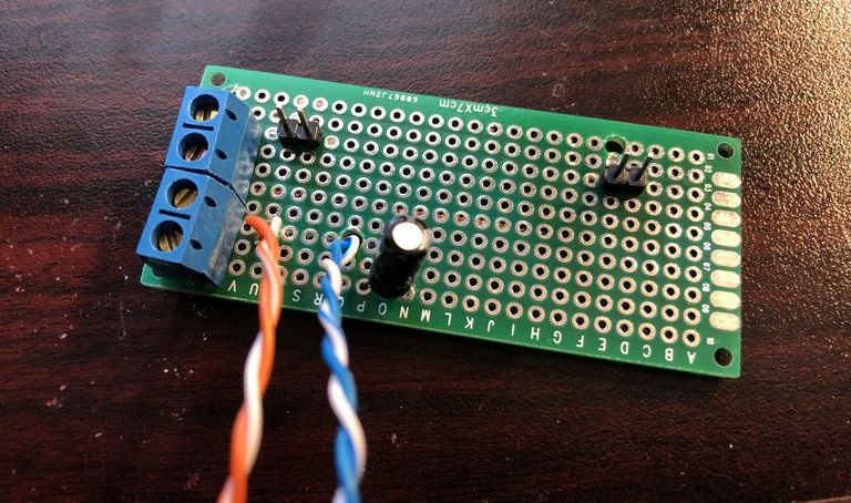
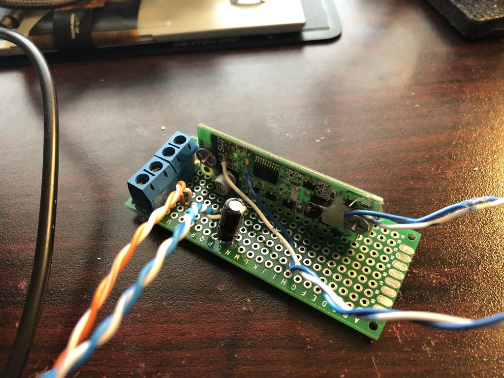
So, let's take 3X7 DIY Prototyping Board and drill few wholes in it. 2 of them to secure board on Raspberry Pi, 1 or 2 others to send wires thru:Put capacitor, and other staff on. Pin headers will bee used to mount security+ board, terminal block to connect to garage door opener wires:
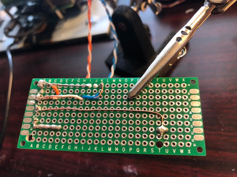
This is bottom, I hope you can user soldering iron better than I do :)
Now, Security+ 2.0. There are 2 push buttons, black to open door, white to turn on light. Solder twisted wire to both of them (I removed white button):
And now, put it all together:
-
4Secure Frankenstein on relay shield, and connect wires to relays
![]()
-
5Convert ignition switch into on/off switch for PRi and motion detector
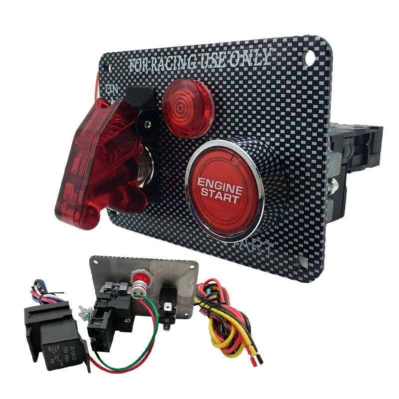
There is bunch of them on ebay, with various buttons, I picked a simple version, one switch to turn on/off RPi and one button to open car trunk or something else...
So, take ignition switch like this one:
![]()
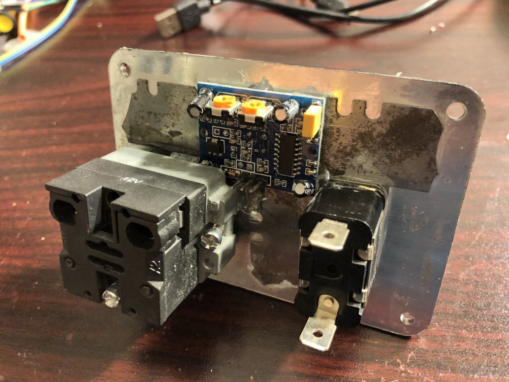
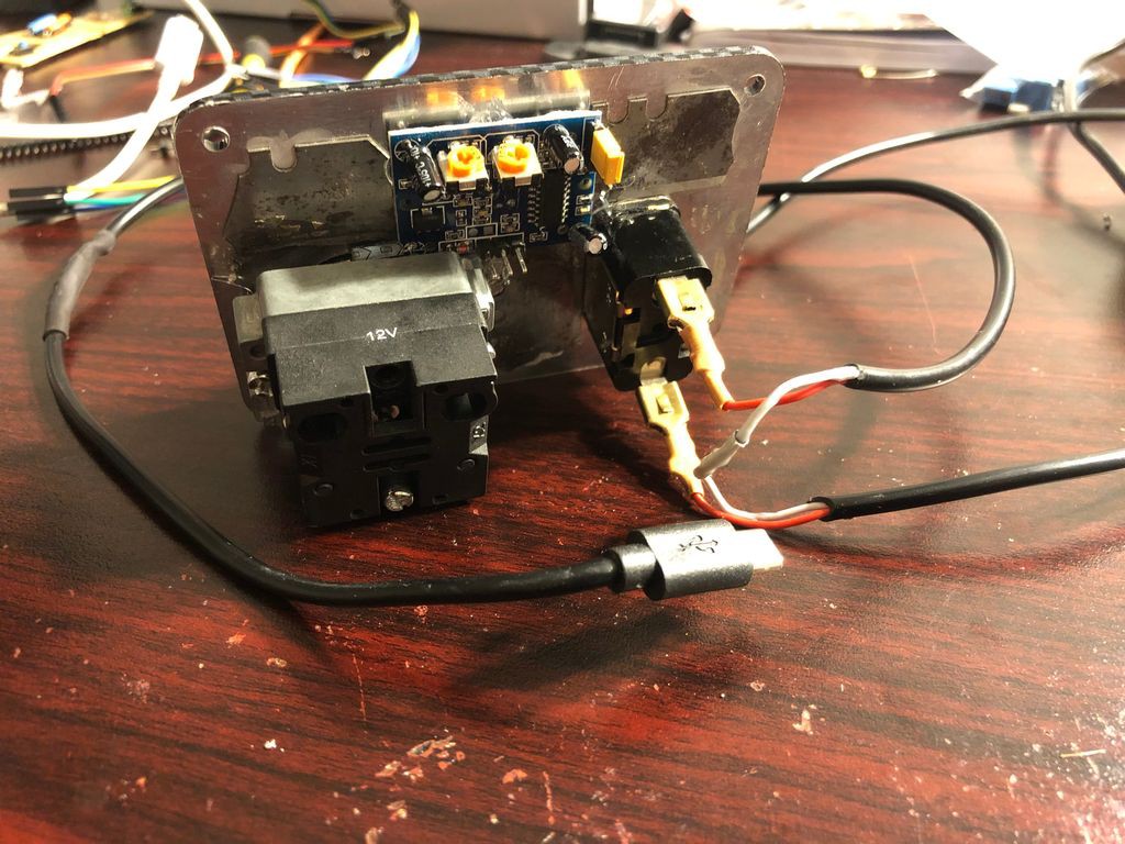
Remove light bulb,. and put motion detector on it's place. I used hot glue gun for that.
Also if you take big motion detector like on the picture, you may need to use lens from a smaller version
-
6Wire on/off switch
And now, wire ignition switch into USB cable, so we can turn RPi on/off or reboot it if needed
-
7Put it all together
Now connect USB power cable from switch to display, and motion detector to RPi,
Depending on version of detector you will need to connect VCC to 5 or 3V, ground to ground and out to GPIO17
![]()
-
8Install it on the wall
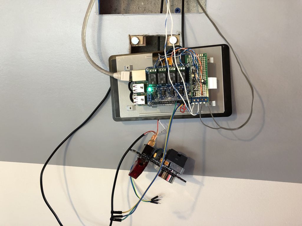
Connect RPi to Ethernet and power supply thru ignition switch, garage doors to Frankenstein, motion detector to GPIO17, and put it into the wall.
As I mentioned before, display with RPi is not secured, it sitting well on it own weight, and for ignition switch panel I used magnets, so I can take panel off when needed:
![]()
-
9Install software
Smart garage control panel is a pretty small GTK+ 3 python application, so all what you need is to install few additional python packages to support GTK, copy program, and add it to auto start.
I guess you already have Raspbian installed, so you can just follow steps on my github:
-
10Test it
This is the most important step. I guess you don't want your garage doors open if power goes off, or RPi rebooted for whatever reason, so test it hard. Turn RPi on and off, reboot it, use switch to simulate power outage
Smart Garage: Control Panel
As many buttons as you want. Any additional widgets. Other capabilities are on the way
 Sergey B

Discussions
Become a Hackaday.io Member
Create an account to leave a comment. Already have an account? Log In.