LibreCAD
I am migrating from DeltaCAD to LibreCAD. So far LibreCAD has proved to be stable.
The DeltraCAD user interface is much better than LibreCAD from the point of view of minimum mouse/hand movements and less steps to do things. I should point out that DeltaCAD is not an AutoCAD clone. LibreCAD is slower to use as most things need more steps. If you use CAD all day you will appreciate keyboard short-cuts (avoiding menu mouse movements) and minimal steps. Especially as you get older.
Other issues are that some of the commands are not functional are rather primitive, "Polyline Equidistant" is an example. Can't expect everything for free!
As I have to run DeltaCad under Wine, losing the macro language and the fact it does not support PolyLine (only lwPoyLine), I have to migrate.
(Well I could use VM VirtualBox and Windows with DeltaCAD!)
Changes to the Gear Ratios
I want make the elbow as compact as practical but the current Sun gear is too small for the stepper motor hub. Rather than increase the overall gear set size, I have changed the gear ratios to make the Sun gear larger (and the Planetary gears smaller) without chaning the outer diameter.
I am now using 24/18/57 and 18/57 gear ratios.
I also increased the Diametral Pitch to 1.0 and 0.928571429. This reduces the size of the gear set to ~75 mm diameter.
To calculate the Diamteral Pitch ratio use (57-21)/(60-21).
Laser Cut Design
The design is built up in layers using 6mm thick MDF. A single layer was no really good enough for the SCARA Prototype. The thickness need to be at least doubled.
The final design will have 1 mm alignment holes and glued in most cases.
Where disassembly is required M3 bolts will be used to hold the pieces together.
Bearing surfaces need to be lubricated with wax or silicon spray. However a paper spacer most likely will be required to give some bearing clearance. Other bearing types (teflon?) may be considered later.
The laser cut diameter for the guy I use is about 0.1 mm. The cut quality varies, sometimes he cuts too slow, sometimes his machine is out of alignment. Given the gear teeth are quite small, an allowance for this probably should be made. LibreCAD's polyline offset does not work so I will have to make this adjustment in the gear code.
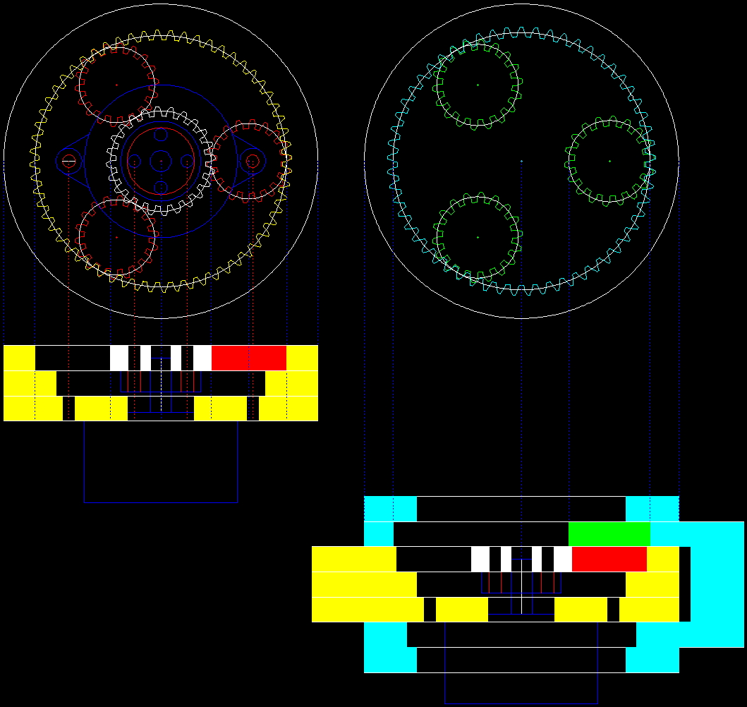
Here is my preliminary design. The lower layer is optional but is designed to increase the joint stiffness:

Notes:
- The yellow layers are the left arm and the cyan the right arm.
- The "gaps" in the layers are provision for mounting bolts.
- The blue outline is a Nema16/17 stepper motor and mounting hub.
- White, red and green are the inner gears.
- If I did not have to make allowance for the stepper motor mounting bolts, the drop down into the layer with the hub, reducing the elbow thickness by two layers.
Planetary Gear Retainer or Cage
It is possible to add a 6 mm thick planetary gear retainer in the upper layer or a 3 mm thick retainer in the hub layer. It is assumed the retainer axles are not concealed.
At this point of time I don't really thick they are needed in this application.
Using Acrylic
Acrylic (perspex) is nice looking material but has some undesirable properties.
- It not very stiff and it stress fractures over time.
- And special glues are required.
I suspect there a different grades of acrylic and the stress fracturing is a feature of the cheaper grades.
If the MDF version work out okay I may look at an acrylic version.
More Planetary Gears
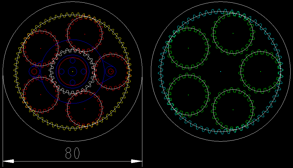
It is possible to add more planetary gears by changing the outer gear ratios. It seems like a good idea. I had a play and I came up with a five planet design (25/20/65 and 20/60). I set the outer gear diameter to 80 mm. Still using a first Diametral Pitch of 1.0 (i.e. gear teeth are 3.14 mm apart):

Retaining Ring
I may as well design the retaining ring for the planets. I can try with and without. I will put it in the top layer (above the green planets in the image above).
Next Step
I think I am ready to detail the elbow design for manufacture. The five planet design will have a less reduction than the three planet design.
AlanX
 agp.cooper
Discussions
Become a Hackaday.io Member
Create an account to leave a comment. Already have an account? Log In.
For joints that do not need to revolve 360° there is another layout to try: Using symmetrical planets with another layer of the input gear on top. The output ring gear gets sandwiched in between two fixes input ring gears (or vice versa). This way the tilting forces at the planets cancel out. As those two rings need to be connected they block the arm connected to the output gear from traversing the full 360°. But as this design encloses the input gear even now nothing is really lost.
Same setup can be used for transmissions that use a belt or another gear as output and only need to access the output ring gear from one side.
Are you sure? yes | no
I would love a drawing, but I will work my way through your suggestion.
Okay I worked out what you mean.
Are you sure? yes | no
Neither MDF nor acrylic are good materials for this. I would rather use (birch) plywood or POM. Both do cut well with a CO2 laser and have better mechanical properties. Using MDF or acrylic for prototypes should ofc be fine. Still I prefer poplar plywood for prototypes for being cheap and quick to cut.
Are you sure? yes | no
I'm curious how you adjust for the kerf of the laser with LibreCAD. I used to use it all the time, but using the offset command on everything and then trimming everything got really tedious. I'd love to go back to LibreCAD, since using Inkscape for precisely-dimensioned parts feels almost sacrilegious.
Are you sure? yes | no
LibreCAD is at best incomplete here. It assumes 1 mm offset and the algorithm need work. As it is open source I may rework this myself but not now.
Writing stable offset code is not a simple as it seems. I have played with it before.
Quite a bit of LibreCAD is under developed. However I have to make the move.
I added the offset for the laser cut width in the gear code a few hours ago.
AlanX
Are you sure? yes | no
Part of the reasoning behind the pressure angle of 24 was it allows for a wider base for the teeth. This does help with making them stronger when 3D printed, and should also help with snapping them off when laser cut out of acrylic.
Are you sure? yes | no