Update May 15th, 2019
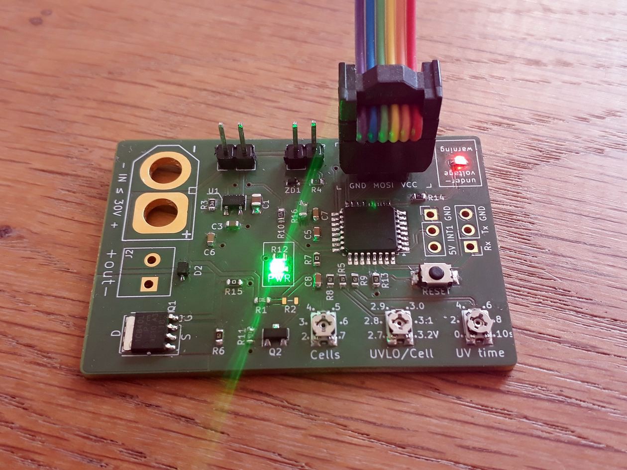
Just soldered the first V0.2 board on a hot steel plate:

It works, burned the bootloader (for fuses) and the blink sketch. Runs just fine. Next I'll try to read the three pots and switching the MOSFET on/off.
Edit: Everything seems to work so far. Will post an update soon to keep you posted!
Update May 14th, 2019
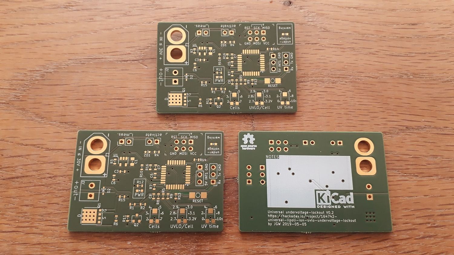
PCBs arrived:

Hope I can test them this week!
Update May 13th, 2019
Got all of my parts, the PCBs will arrive this week as well. Hope to get the first prototype soldered before the weekend!
Update May 5th, 2019

So, as I said earlier I didn't like my first v0.1 design. Digging through the schematic again before sending the board off to the fab I saw a few things that wouldn't quite work the way I though they would.
Here I'd like to thank @Simon Merrett for his support! He had a lot of good advice to give and helped me getting some things sorted! Sometimes some stranger asking "why this", "why that" is everything that's needed to question some of your decisions :)
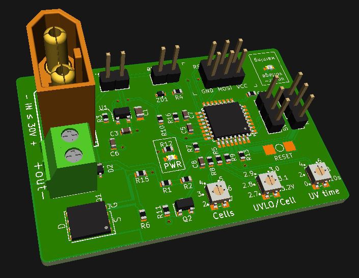
The board now is:
- smaller (52x35mm)
- tidier
- cheaper (less expensive parts)
Of course this still is not the final thing, but if it works as expected, getting it smaller will be no big deal.
We'll see. Boards are ordered, parts are on the way too...
Original post - just for reference
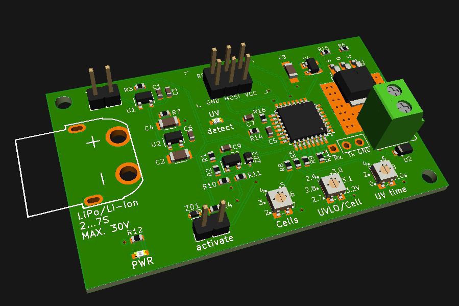
Okay, so this thing is not a beautiful piece of hardware. To be honest I don't like it myself, the layout is very shitty and much space is wasted. But I need a first revision to get myself started :)

This is not how the final board will look like, not at all.
Things that'll change:
- size-wise
- board must be smaller. I aim for 50x35 or 50x40mm
- limit height by removing those header pins and screw connector (need them for debugging and stuff)
- hardware-wise (going cheaper!)
- Atmega328P is overkill. Will work with an Attiny24A-SSU or something like that. Much cheaper, too at 0.65€
- looking for a substitute for those pots. Ideas?
- U4 is a MIC5018 boosted MOSFET driver to have a constant 10V drive voltage regardless of the input voltage which can be lower! At 1.1€ those are expensive. MIC5018 is half of that. Anyone know a similar chip?
- smaller caps will be used. 1uF @ 50V in 0603 are super cheap and much smaller than the 1206 I am using at the moment
- (…)
 Jan
Jan
Discussions
Become a Hackaday.io Member
Create an account to leave a comment. Already have an account? Log In.
Re: Update May 13th 2019 - hooray!
Are you sure? yes | no
@Jan , you're welcome! Now I see the mechanical design (rather than the electrical stuff we have been discussing), maybe some decent mounting holes at the XT60 end would be good - those connectors can take a bit of force to make/break.
Are you sure? yes | no
Right! The last version had an XT60 90° connector with two support pins. Guess what I forget to include with my order at LCSC!
The final board will have that lying connector again, same for the output. Which will then be on the opposite side again as well.
Are you sure? yes | no
@Alan Green Those dev-boards look like "better" Arduino Nanos! Too bad it needs AS7. The problem is not ME but I would love to make my board programmable/hackable by the community as well.
This unfortunately restricts me to the older range of Attinys and Atmegas. At least until UPDI-programming is more common.
Need to get me one of those dev boards though!
Are you sure? yes | no
I think the appetite of the community will be bringing those new chips into service pretty quickly with cheap and OSS/OSH toolchains. For example, @Alan Green mentioned pyupdi and I have successfully pressed an Arduino Nano clone into service as a jtag2updi programmer to upload from avrdude and AS7 to ATtiny402. The serial programming elements of avrdude.conf can't be used so reading and flashing fuses from there isn't a straight forward thing but I would wager that people will soon have that door smashed down. PS, there are some signature HW bugs in some of these newer ATtinys, so be prepared if you try them barebones, rather than on a dev board!
Are you sure? yes | no
While you're looking at the Attiny24, you might also consider the 0-series and 1-series chips. The Attiny204 is roughly equivalent to the Attiny24 but about 2/3 the cost. The 404 is about the same price as the 204 and has double the RAM.
Also, for the same price as the Attiny24, you could get an Attiny416 in a 24-VQFN package, which will give you 21 I/Os after accounting for power, ground and UPDI pins.
The downside of these new chips is that they aren't supported in an Arduino library yet.
Are you sure? yes | no
@Alan Green I also think they'd be good options, depending on "pin creep"! Do you have any good resources for working with them? I have basic programming going with AS7 but would like to get fuses sorted with avrdude if possible
Are you sure? yes | no
I've been using the standard (I guess soon-to-be-legacy) commercial toolchain of AS7 + START + Atmel ICE. Between the generated libraries, datasheets and the odd peek at Arduino library source, I've had plenty to go with.
I'm currently curious about the new toolchain with MPLAB IDE and the $20 MPLAB Snap programmer.
If you're wanting to go really cheap, you could look at https://github.com/mraardvark/pyupdi for programming, but it lacks debugging capability.
Are you sure? yes | no
Hi Alan and thanks for your input!
Indeed, those Attinys look good. The 416 seems perfect for my needs. As all the functions are quite low level, I can program it bare-bones without Arduino "IDE".
The Attiny204 is even cheaper. I'll def. look into those!
Are you sure? yes | no
Ooh. If you're looking at the 416, check out the $10 416-xnano dev board. If you're using Atmel Studio 7, it Just Works.
Are you sure? yes | no