-
06 – new DC/DC buck design
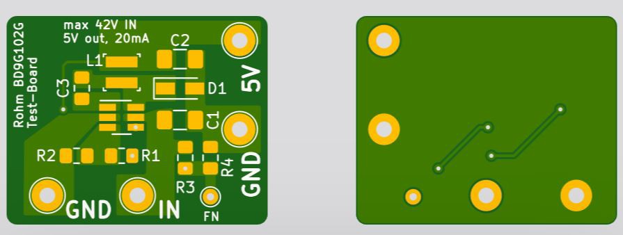
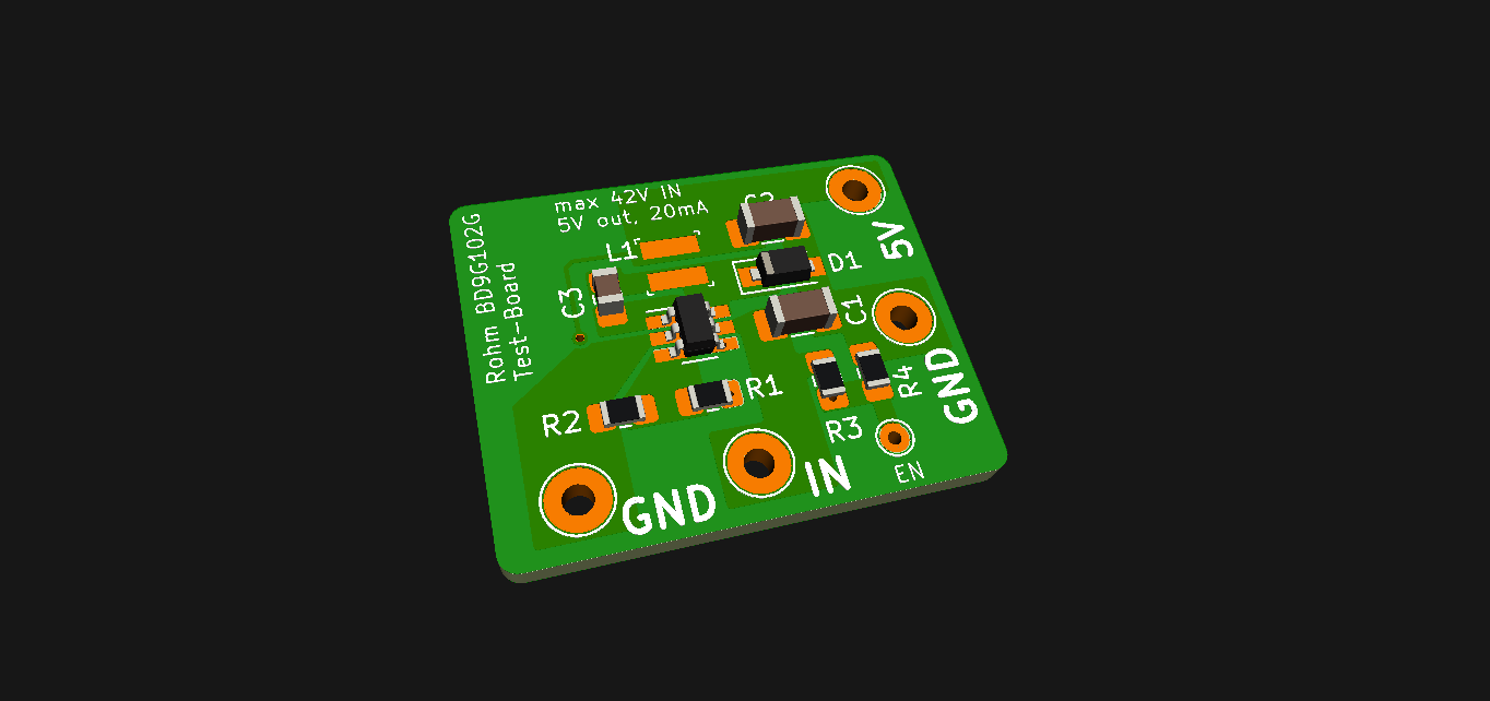
06/25/2019 at 20:41 • 0 commentsAfter all but the last regulator blew, I wanted to test a DC/DC power supply next. So I quickly made a little board around the Rohm BD9G102G-LB DC/DC buck regulator which is quite close to the reference design from the datasheet.
Aisler online rendering ![]()
KiCad rendering - parts included The boards are 25x20mm in size. I use a bigger inductor than is probably needed for 20mA max output, but I wanted to try a few different ones and look at the output waveform on my scope. Rally can't tell how the ripple will affect the ADC readings of the chip. We will see how that works out. Found a nice paper on reducing ripple by TI...
I'd love to use a small 1206 chip inductor to keep everything nice and small! Resistors and caps will be 0603 instead of 0805 too for the final board.
I ordered three copies of the board together with all the parts for 18.30€ from Aisler in Germany, so I expect them to arrive in 7 or 8 days as they usually do. The parts are sometimes a bit more expensive when ordered through Aisler, but you don't have to come up with other stuff to get to 50€ free shipping at Digikey, so that's fine I guess...
Hope this design works :)
-
05 – project is not dead yet
06/21/2019 at 09:03 • 7 commentsSo, after having so much trouble with the failing regulator I finally found the culprit: the regulator needs at least 4.7uF of ceramic capacitance at its INPUT to keep it from blowing up.
This does generate another problem which is arcing when connecting a battery, caused by the near short circuit behavior of an discharged cap...
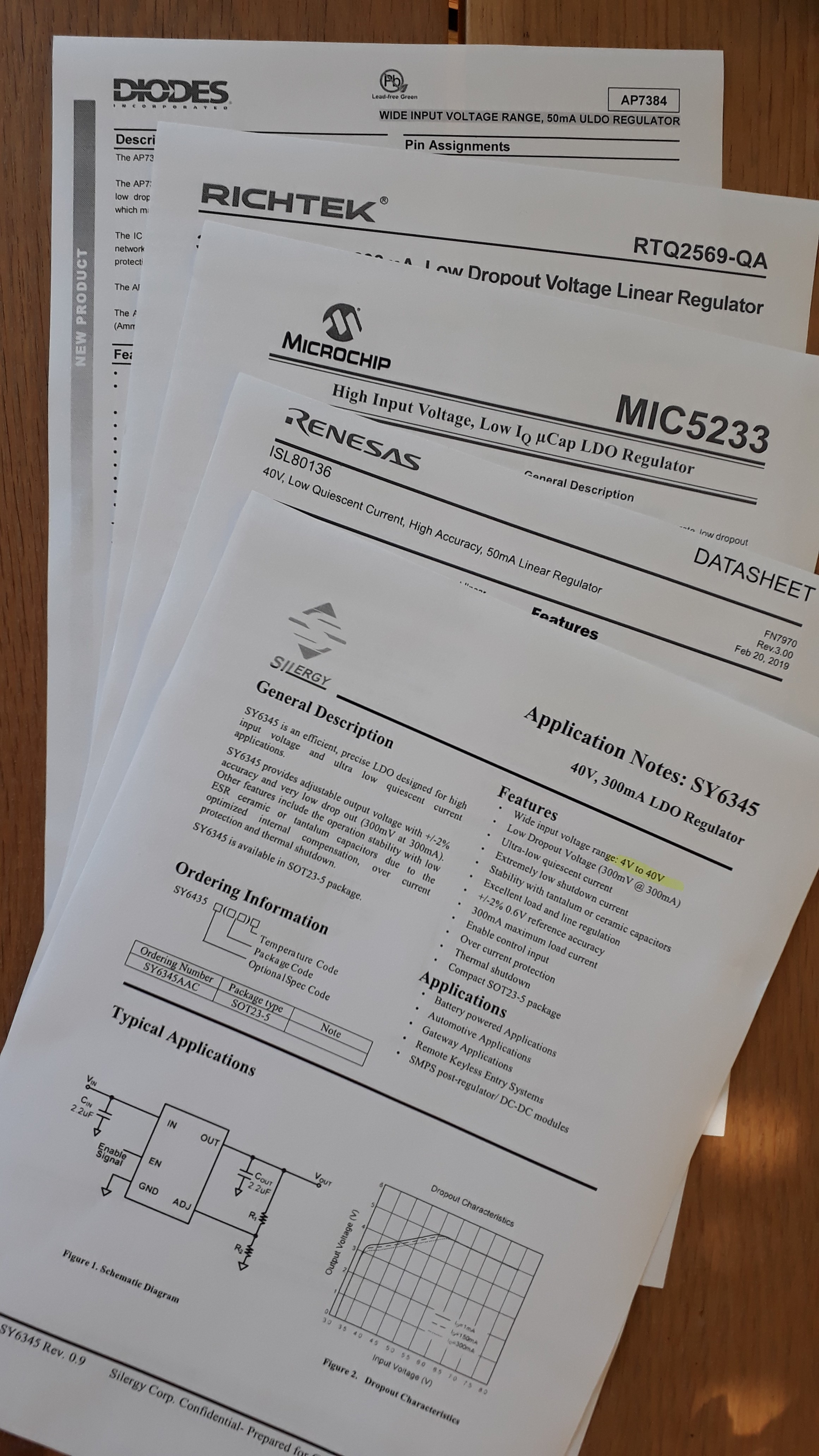
So to keep things short I found a few other regulators that I want to try:
![]()
I'll decide for one and come back to you with a fresh design.
-
04 – unpredictable? regulator fails :( HELP!
06/17/2019 at 19:12 • 0 commentsAaaaaaaaaah!
After I did the first tests with the first board (and writing my very happy post about it) the next day I connected the board to a fully charged 6S LiPo battery again and got... the magic smoke.
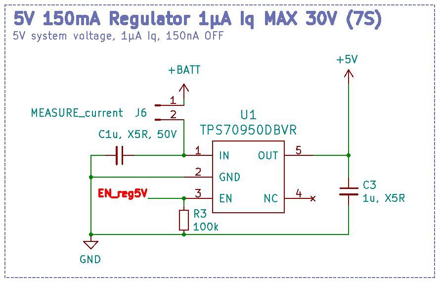
the circuit in question After inspection of the board it was obvious that the regulator blew. I double checked all the parts in the schematic, found no obvious error and re-worked the regulator and Atmega328. It worked a few times after that.
A few days later I even did rests with the same LiPo and a 150W electronic load to test the MOSFET for heat dissipation. Worked like a charm.
Then on some random re-connection of the battery blew the regulator (and micro) again. DOH!
Tests I did
So, I did solder just the TPS70950DBVR on an breakout board, added the caps needed (50V rated, low ESR MLCC) and did some tests again.
Leaving EN floating (according to the datasheet) and with no load connected, the regulator seems to be super sensitive to repeated quick connection of 30V with a high current capability (DSP5005 srt to 30V/5A).
It seems like the inrush-current can kill the regulator?! At least that's what happened a few times. I'm through 6 of my 10 regulators now...
Did the same tests with an 100 ohm load resistor to simulate 50mA output current and saw some heavy heat-up of the regulator with a over-temp shutdown by the regulator. With 20mA output it got quite hot but didn't shut down.
Connecting the 30V current-limited to like 100mA seems to reduce the chance of the regulator popping.
Conclusion
I really can't reproduce the error reliably... The inrush-current theory is just that, a theory. I tried several other things which I thought could be the reason for failing, like: too high enable voltage, wrong caps, other style of caps, wiring, ...
To sum things up: the boards are NOT going to production any time soon. Did check several other regulator options but can't seem to find any good one yet.
-
02 – v0.2 boards fully functional!
05/16/2019 at 20:17 • 1 commentIn my last log I mentioned just a few quick things. Now it's time to tell you the following:
My v0.2 boards are fully functional without any modification. Can't remember when this happened the last time, if ever :)
A few notes:
- current consumption when active in the single digit mA range
- current consumption when OFF: 0.45µA
- wake-up from OFF-mode only by pushing a button connected to the board
- pushing reset == OFF
I wrote a quick first-try program for the boards which I will refine a bit next week and upload.
When this is done, you could order those boards, solder them and add them between your valuable rechargeable batteries and your devices.
I'll put up all the needed files shortly!
-
03 – cutting costs
05/01/2019 at 10:20 • 1 commentWhat is the aim?
This log is all about: How can we make the whole board cheaper while keeping all the features and not killing its safety functions. This all refers to the early v0.2 version which is by no means optimized yet!
Ways to cut costs
I try to think of mass production here (Disclaimer: I AM NO PROFESSIONAL, it's just what I would do to keep it cheap).
Let's say we want to make a thousand of those boards to sell them. A few thoughts come to my mind then:
- less parts = cheaper
- substituting expensive parts with widely available "china brands" = saving costs
- using jellybean parts and same footprints
- smaller boards = cheaper
- boards need to come fully assembled
- [...]
Let's get into more details here
The above points will be anatomized in greater detail here.
1 – using less parts
This is a no-brainer, right? It's not as easy as it sounds. Most parts are there for a reason, so we need to look at every part and ask ourselves: do we really need it?
Here are a few parts which can be substituted by other brands but can not be left out altogether:
- Microcontroller: needs to be there for all the main functions and hackability
- MOSFET: our main-switch
- input and output connectors
- a voltage regulator: we need at least a low-Iq 5V rail for our logic-level MOSFET
- a few caps at the various inputs of the chips for stability
So, if all those parts are needed, which parts could we possibly cut from the list? A decision in this category usually has some effects on other parts of the circuit.
1.1 - choosing another voltage regulator
The TPS70950 is a nice LDO voltage regulator with an EN-pin and <0.1µA quiescent current in shutdown mode. Neat! But this comes at a cost: €0.3395 per piece buying 1000.
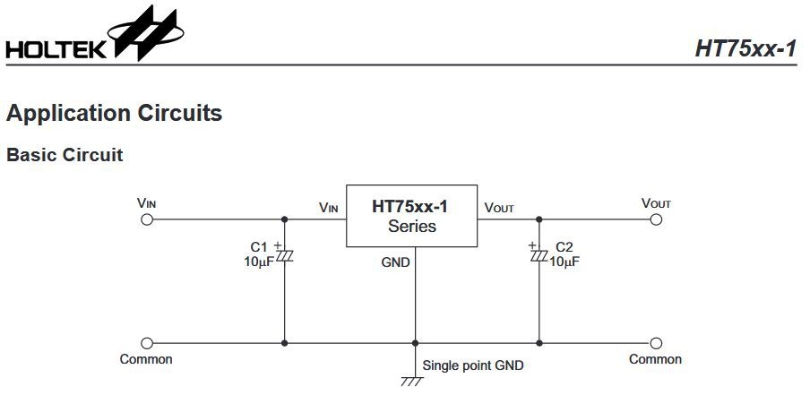
No we need to ask: what OFF-current draw can we accept? From other circuits I know we can get ATMEGAs and ATTINYs down to around 2µA total using a system load switch. Say, we would accept 10µA total OFF-current. This doesn't drain an already "empty" cell too much. So we have 8µA for other parts. A hint from @Simon Merrett was using an HT7550-1 from Holtek. These draw max. 3µA idling (with no load), having no EN-pin though.
Fits our bill perfectly! Costs €0.075/pc buying 1000. Here's what I mean with changes down the line when substituting components:
voltage regulator in v0.1 Looking at the circuit above we can use the HT7550-1 instead:
The 1µF caps can stay in place, no need for 10µF in our circuit, cause it uses only little current.
Changes to the circuit are:
- the EN-button needs to be tied to one of the µC's interrupt pins
- ZD1 can be left out as the 5V rail will be always on. While not exactly expensive it's another saving!
- R3 can be omitted as well
Total savings: Around 87%. or 265€ per 1000 boards.
1.2 - choosing another MOSFET
With MOSFETs it's a bit more like "pay less get less". Considerations are:
- Switchable current 8A (10A) max.
- max. input voltage 30V
- no mounted heatsink
- small PCB area
So, we need a type with a maximum drain to source voltage of > 30V to keep the MOSFET from destruction, that's why I chose 40V (the v0.1 one has 30V max.).
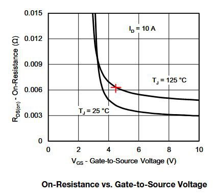
Next consideration is the resistance RDSon at a gate voltage of 4.5V. Datasheet values are mostly for a MOSFET silicon temperature of 25°C. So we need to de-rate it with the given value of the datasheet to be sure it is proper low resistance even when hot.
With little board-space we need to take the heat-up into account which is around 50°C per W of "wasted" current.
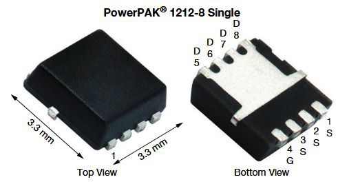
A quick look at Digikey presented me the SiSA72DN.
On-resistance is around 0.007 ohm at a die-temperature of 125°C and 4.5V gate-voltage.Fits our needs perfectly and has a very small footprint too:
Power dissipation at 10A will be 10² x 0.007R = 0.7 Watt. This would heat the MOSFET to around 25°C (given a surface mount on 1x1" copper on FR4). Let's see if we can give it that much space. This will be worth another complete log.
The Toshiba is 0,86516€/pc @ qty1000, while the Vishay SISA72DN is 0,18778€. Saves 677.38€ per 1000 boards.
1.3 - choosing another microcontroller
This one is a real cost-driver! I chose the Atmega328P because I use it for most of my stuff and have many of them in my drawers.
For a mass-produced board this micro is too expensive, because I don't need that much FLASH, nor do I need all those in and outputs. To keep the board programmable and hackable by a huge community I want to have a chip which is easily programmed by the Arduino IDE.
The Attiny-Series have some very interesting options here. After a bit of looking around I selected the Attiny261A in a VQFN30 case.
It has enough IO's and is cheap enough. Atmega328P-MU is 1,52640€/pc @ qty1000, the Attiny261A is only 0,31950€. Saves 1206,9€ per 1000 boards.
To be continued...
-
01 – boards v0.2 ordered for tests
04/27/2019 at 11:20 • 10 commentsUpdate May 15th, 2019
Just soldered the first V0.2 board on a hot steel plate:
![]()
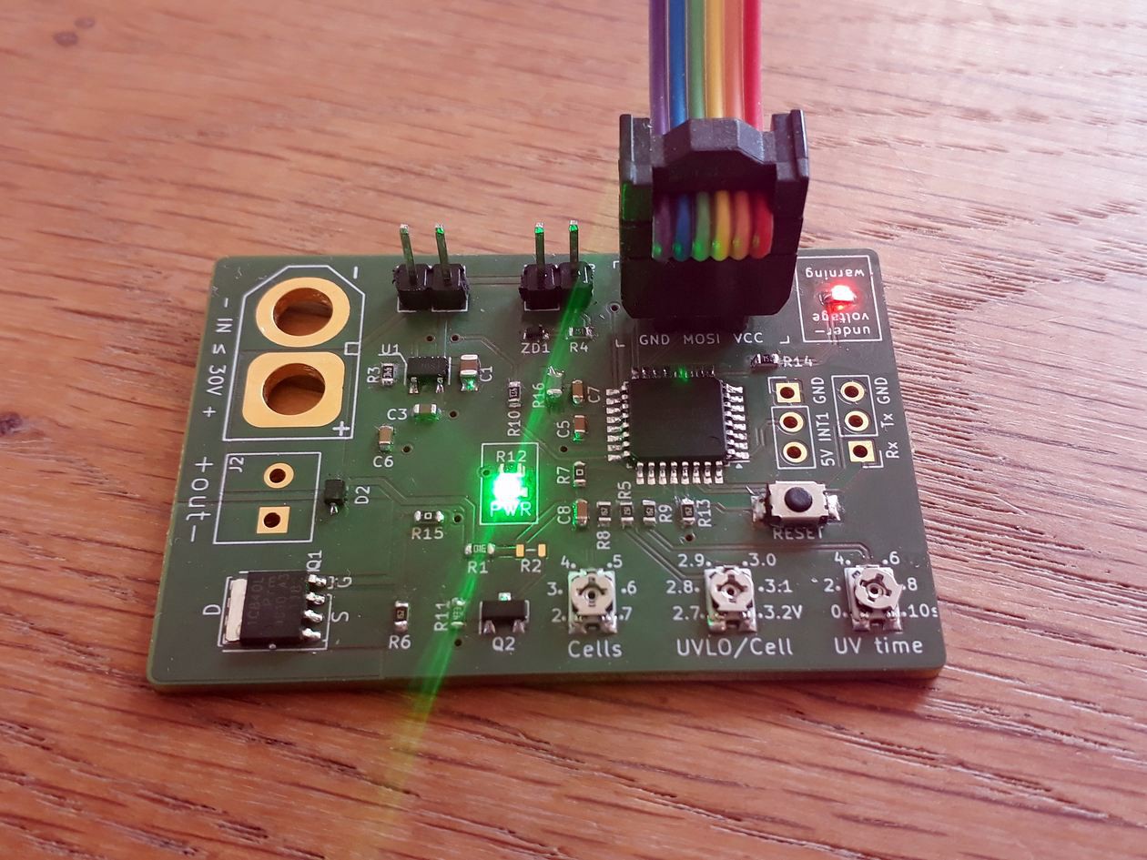
It works, burned the bootloader (for fuses) and the blink sketch. Runs just fine. Next I'll try to read the three pots and switching the MOSFET on/off.
Edit: Everything seems to work so far. Will post an update soon to keep you posted!
---------- more ----------
Update May 14th, 2019
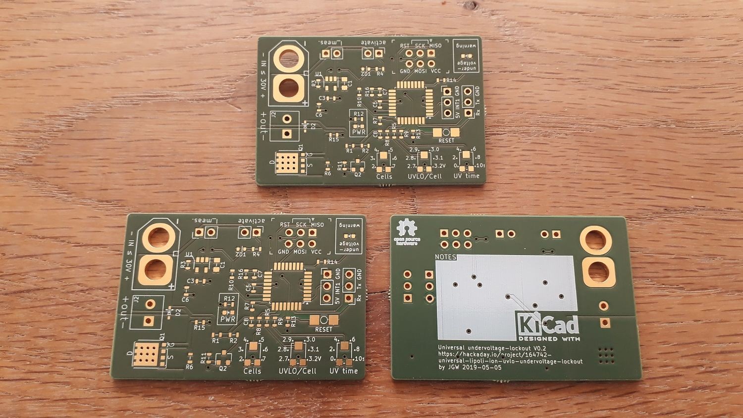
PCBs arrived:
![]()
Hope I can test them this week!
Update May 13th, 2019
Got all of my parts, the PCBs will arrive this week as well. Hope to get the first prototype soldered before the weekend!
Update May 5th, 2019
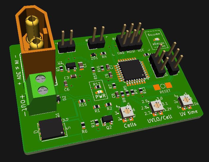
v0.2 - sent to the fab on May 5th 2019 So, as I said earlier I didn't like my first v0.1 design. Digging through the schematic again before sending the board off to the fab I saw a few things that wouldn't quite work the way I though they would.
Here I'd like to thank @Simon Merrett for his support! He had a lot of good advice to give and helped me getting some things sorted! Sometimes some stranger asking "why this", "why that" is everything that's needed to question some of your decisions :)
The board now is:
- smaller (52x35mm)
- tidier
- cheaper (less expensive parts)
Of course this still is not the final thing, but if it works as expected, getting it smaller will be no big deal.
We'll see. Boards are ordered, parts are on the way too...
Original post - just for reference
Okay, so this thing is not a beautiful piece of hardware. To be honest I don't like it myself, the layout is very shitty and much space is wasted. But I need a first revision to get myself started :)
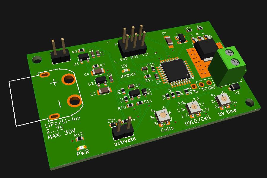
Board revision 0.1 for first tests This is not how the final board will look like, not at all.
Things that'll change:
- size-wise
- board must be smaller. I aim for 50x35 or 50x40mm
- limit height by removing those header pins and screw connector (need them for debugging and stuff)
- hardware-wise (going cheaper!)
- Atmega328P is overkill. Will work with an Attiny24A-SSU or something like that. Much cheaper, too at 0.65€
- looking for a substitute for those pots. Ideas?
- U4 is a MIC5018 boosted MOSFET driver to have a constant 10V drive voltage regardless of the input voltage which can be lower! At 1.1€ those are expensive. MIC5018 is half of that. Anyone know a similar chip?
- smaller caps will be used. 1uF @ 50V in 0603 are super cheap and much smaller than the 1206 I am using at the moment
- (…)
Universal undervoltage lockout up to 34V input
Feature-packed over-discharge protection. Set the cell-count, minimum cell voltage and dip-time below threshold. Fully hackable!
 Jan
Jan