-
15 – testing smart high side switch
11/11/2019 at 17:19 • 2 commentsJust a quickie:
![]()
![]()
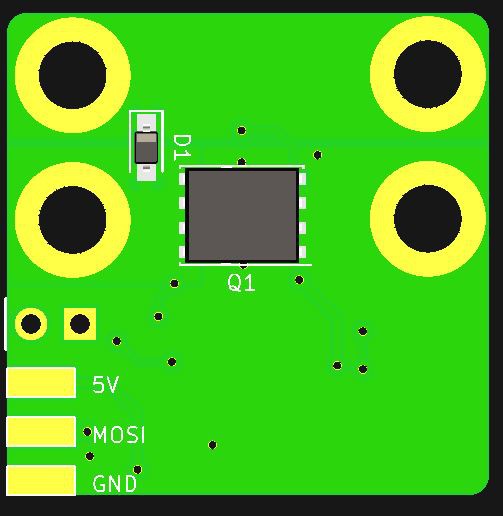
I expect the test-boards for the BTS441RG smart high-side power switch to arrive end of this week.
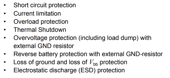
This thing has some awesome protection features:
![]()
The only "downside" is the relatively high Rdson of 20mΩ. But I'll do some thorough tests with this puppy. Stay tuned!
-
14 – what will be next?!
11/08/2019 at 16:38 • 0 commentsWhat's next?
I decided to part the project into two separate ones:
- the square inch one
- the fully featured version with trim pots
Also I decided to rename both projects to the correct technical term, so it is easier found by people who search for this kind of circuit.
The square inch one: LVD² (low voltage disconnect 1x1 inch version)
This is the version which was featured in this hackaday.com write-up. Many readers had great ideas on what to improve with this little board. Honestly, they were all right, it's just that the article simply was about an unfinished board. Anyway, here's what will happen to the square inch version:
- switch from Attiny861 to the smaller but more capable 1-series Attiny816 (or 416)
- implementation of a fuse which will probably be around 15A
- reverse-voltage protection for the board
- cut-out voltage can be set by changing an resistor
- time-out can be set by changing an resistor
Other than that I'll try to make a one-sided board from it to make assembly easier. In addition to that the software will be much different and really small, it will even fit into the Attiny416 which is even cheaper.
The fully featured one: FFLVD
This is the version I had in mind when I began this journey. It will be the more sophisticated but also bigger and more expensive version:
- switch from Attiny861 to the smaller but more capable 1-series Attiny816
- implementation of an over-current protection which can be set to values between 10 and 30A
- reverse-voltage protection for the board
- cut-out voltage can be set by a trim pot
- time-out can be set by a trim pot
-
14 – adventures in current measuring land
11/01/2019 at 16:50 • 3 commentsSo I would like to measure the current flowing in the next iteration of the board. There's many possible solutions to this. I do not need to measure over the full range of 0 to 10 or 15A in mA resolution. My aim is to cut the load off when a certain current is reached.
So let's assume this current I want to cut the load at is 10 ampere. I needed to select a shunt for that. To not waste too much energy (because it is directly in line with the load) it needs to be as low resistance as possible.
Selecting a shunt resistor
So I chose a 0.005Ohm shunt. At 10A there will be (U = R*I) 0.05 ohm * 10A = 0.05V across it, which is 50mV. It will turn (P = R*I²) 0.005 ohm * 10²A = 0.5W into heat. The shunt needs to cope with that, so I chose a 1%, 2W version which comes in a 2512 case.
But how the heck are we going to reliably measure 50mV and turn it into a value that allows the Attiny to work with?
Selecting a proper Analog to Digital converter
There are two ways I'll describe here.
1 – using a separate ADC chip
![]()
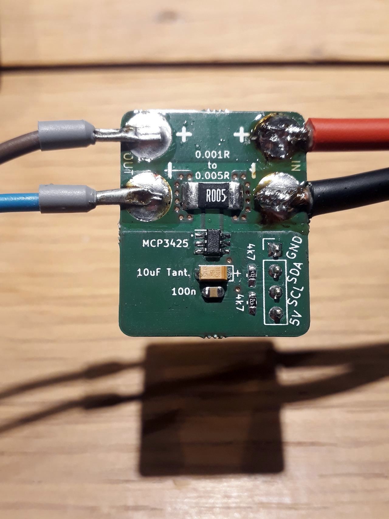
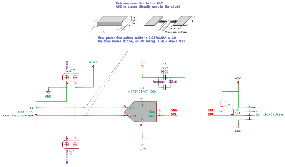
Here's a small break-out board for the Microchip MCP3425 16Bit ADC chip. Here's the schematic:
![]()
As the ADC doesn't accept a voltage >> than VCC we need to sense the resistor voltage drop connected to ground. Sensing is done with the widely adopted "Kelvin sense connection":
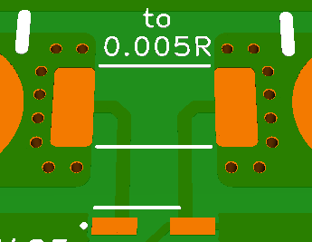
![]()
This eliminates a few problems regarding sensing directly from the main current path. Analog has evaluated an really special footprint design especially for this purpose here. Be sure to check that out as well!
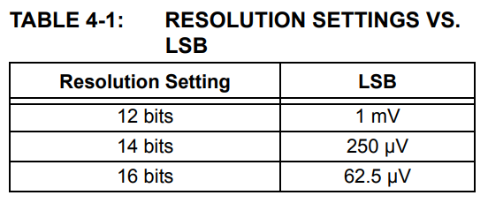
The drop will be super low, so ground shift will be no problem here. These are the resolutions you can get from the ADC:
![]()
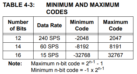
More bits = longer measuring time:
![]()
So, for a quick "just overcurrent protection" we can choose 12 bit resolution. This means a current of 10A gives us a code of 50, which is exactly 50mV in this case because of the 1mV resolution / LSB.
Overcurrent-shutdown will take at least 4.2ms (240Hz sample rate). This could be too long to protect the MOSFET from destruction, I'll have to look into that. A fuse for the absolute max current needs to be implemented anyway.
2 – using only the Attiny816
Stay tuned...
-
13 – square-inch version works ✔
09/18/2019 at 07:07 • 0 commentsUpdate 2019-10-03
![]()
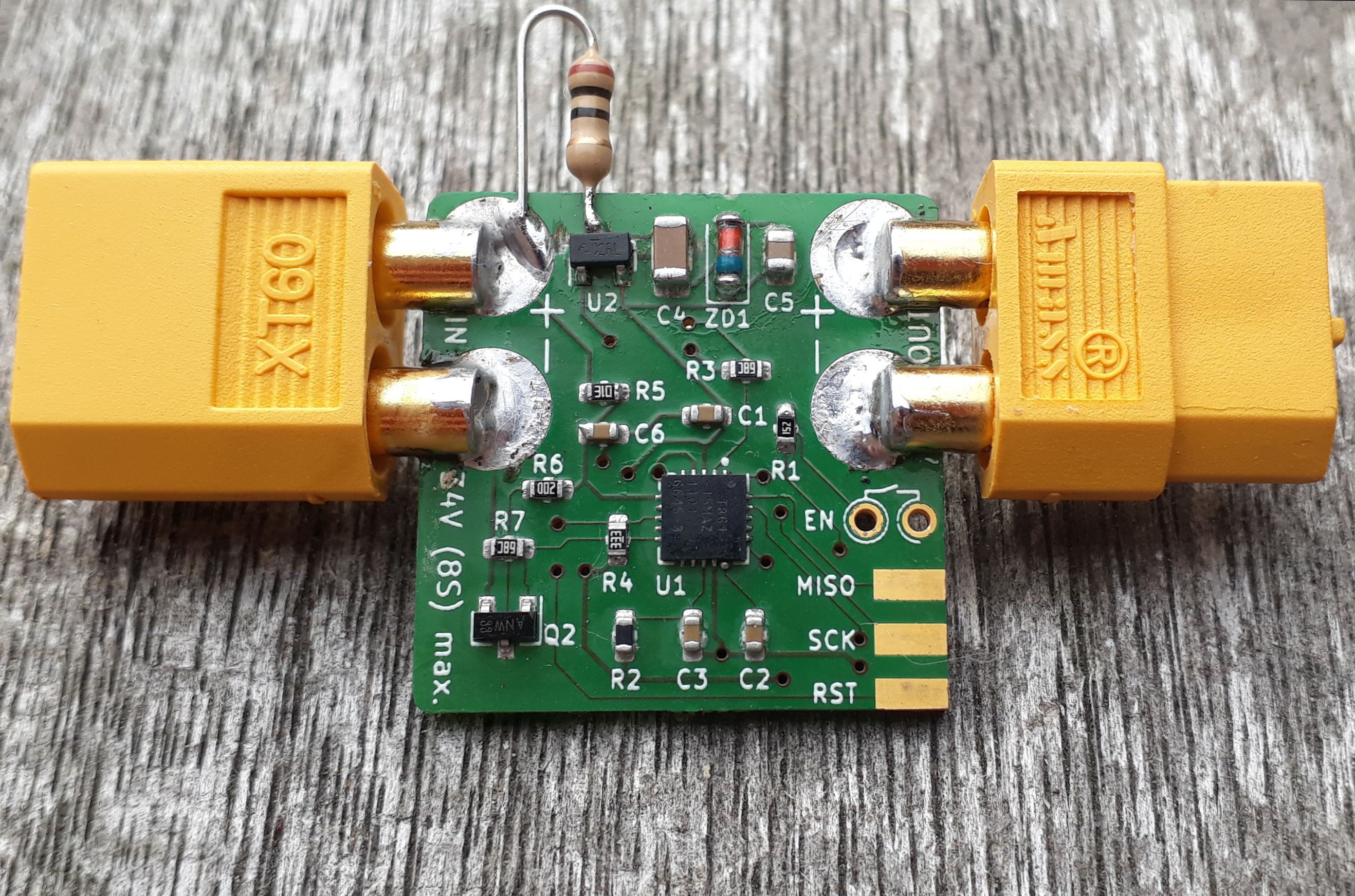
finally working version - see the 10 ohm resistor :) Phew, that was a journey. This project really started killing me slowly... It worked at first but the damn thing tried to die randomly. As I put a 5V6 zener directly into the 5V rail (the reg. has a short circuit current of 20mA only so the zener does not need an resistor) at least the Attiny861 follow the regulator each time it blew...
I tried everything and always thought: Ah, this works now. UNTIL it blew again. Mostly on (re)connecting the LiPo battery. So it had something to do with the inrush current.
When I talked with @Simon Merrett about the issue, he suggested to limit the inrush current to the regulator with a resistor. First I though this is a bad idea because additional resistance in the path means more (quiescent) current.
But I gave it a go. In the above picture you see a 10 ohm botch-resistor. It effectively kills the inrush-current to something which doesn't destroy the regulator.
NOW IT FINALLY WORKS like... ALL THE TIME. Nice!
---------- more ----------![]()
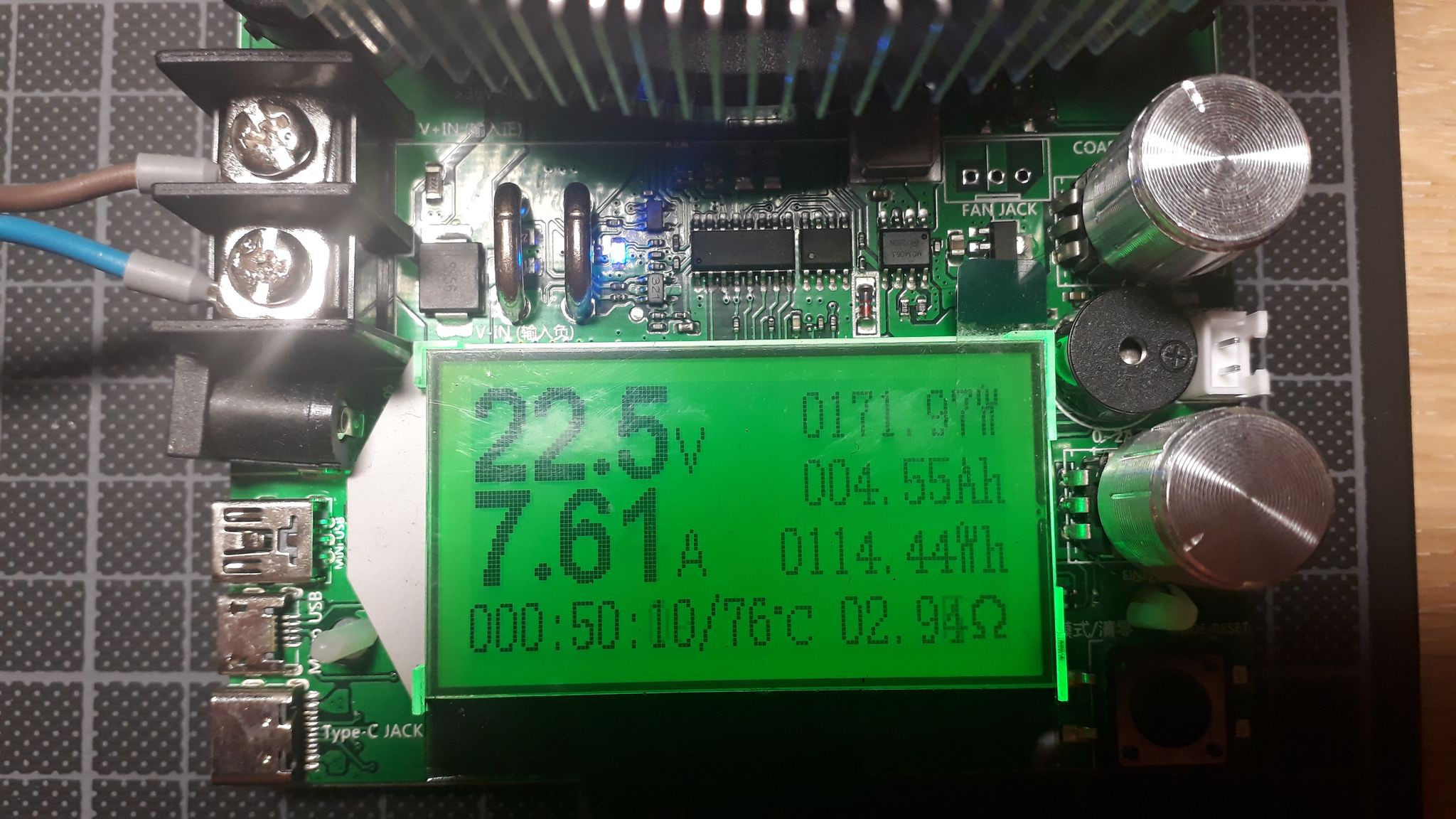
Just tested the board with a 6S LiPo and a electronic load. You can switch a constant 175-180W without the MOSFET getting more than luke warm.
Off-current is 13µA. A bit much for my taste (should be more like 5...8µA) but I guess it's got something to do with the reverse leakage from the 5.6V protection zener (though the datasheet says 2µA reverse current max...).
I'll do some more tests soon.
-
12 – square-inch version ordered ✔
08/15/2019 at 10:33 • 0 commentsUpdate – 20190826
You always seem to find errors when it's too late for changes :)
- used interrupt pin in the "wrong way":
- switching it to +Vbat (via 50k, so the high voltage doesn't kill the pin)
- forgot pull-down resistor
The right way would've been: using the internal pull-up and switching to GND...
C4 should've been directly tied to the regulators input. It is connected correctly to +VBAT and GND, but not as close as possible to the regulator. As the whole board is only 25x25mm it shouldn't be a problem though...
Update – 20190816
Today I finished my square inch design and ordered it at Aisler:
online shop rendering This time I added a stainless stencil for top and bottom because I hate adding solder paste with a toothpick or syringe :)
---------- more ----------Intro
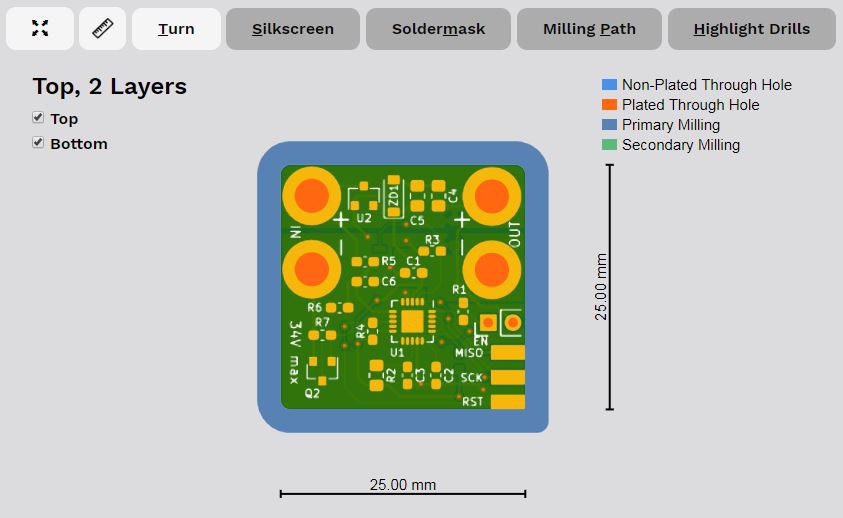
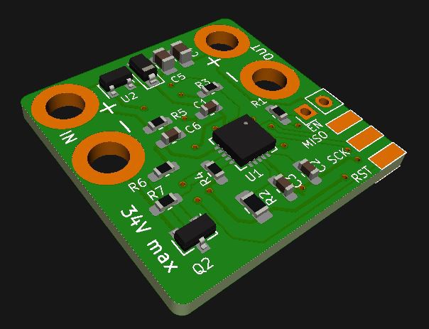
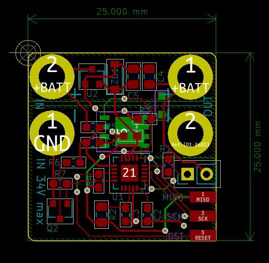
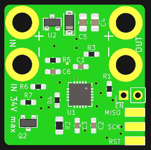
For a few of my planned projects I need the board to be quite small. So I made a very basic version. It misses all the nice "usability" features, the bigger board has.
Facts
The cut-off parameters are set once while programming (and can of course be re-programmed) and there are not LEDs to show the state of the board.
Off-current should be well below 10µA, working-current will be around 1mA when measuring, which is around 10% of the time (while not measuring the Attiny shuts down), so let's assume the working current is around 15% of 1mA, so 0.15mA averaged over time...
The board is 25x25mm in size, it will fit into many many tight spots!
PCB Top Bottom - used interrupt pin in the "wrong way":
-
11 – use case ONE: mobile boom box
08/06/2019 at 16:34 • 0 commentsUpdate – 20190809
![]()
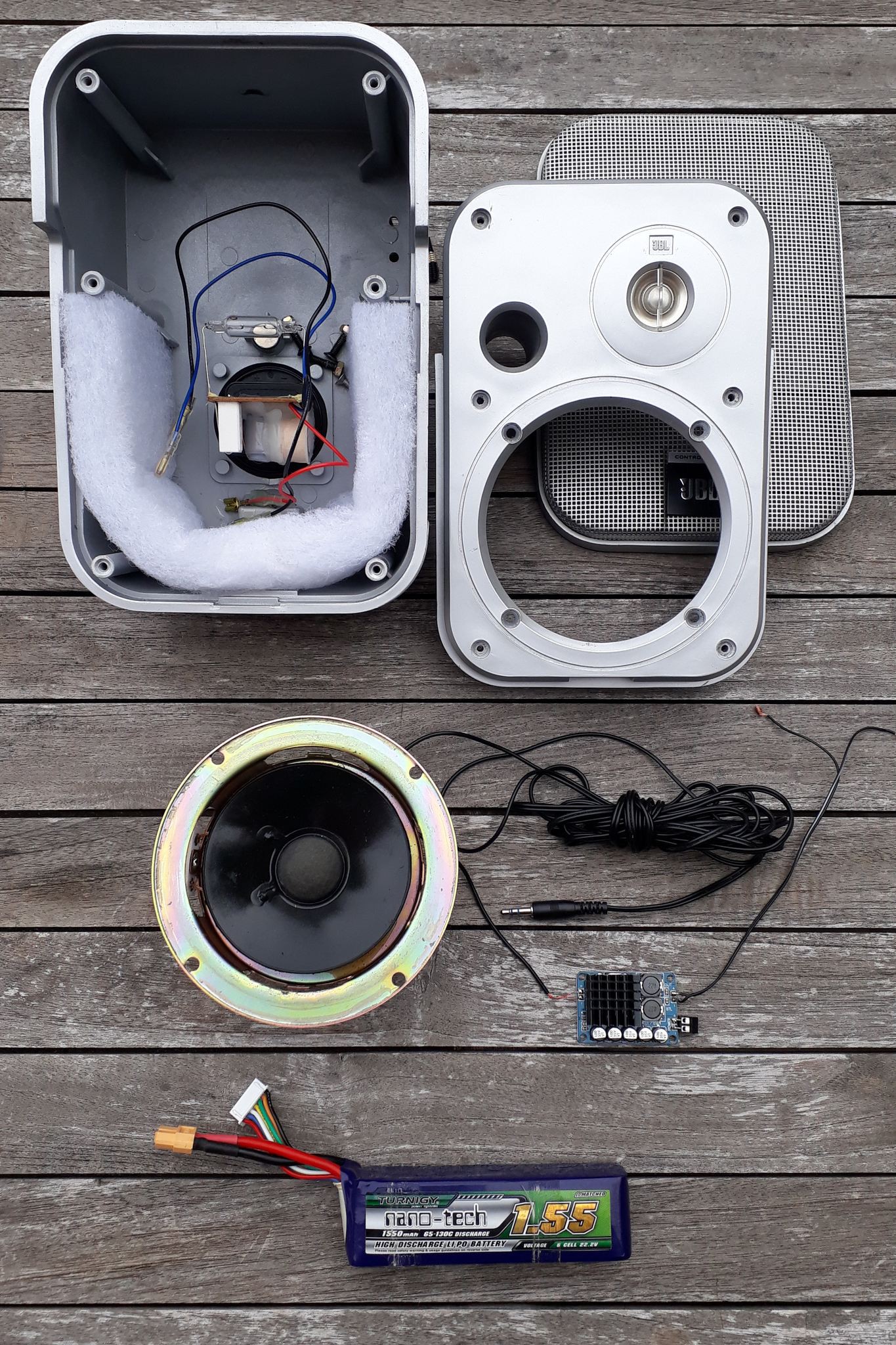
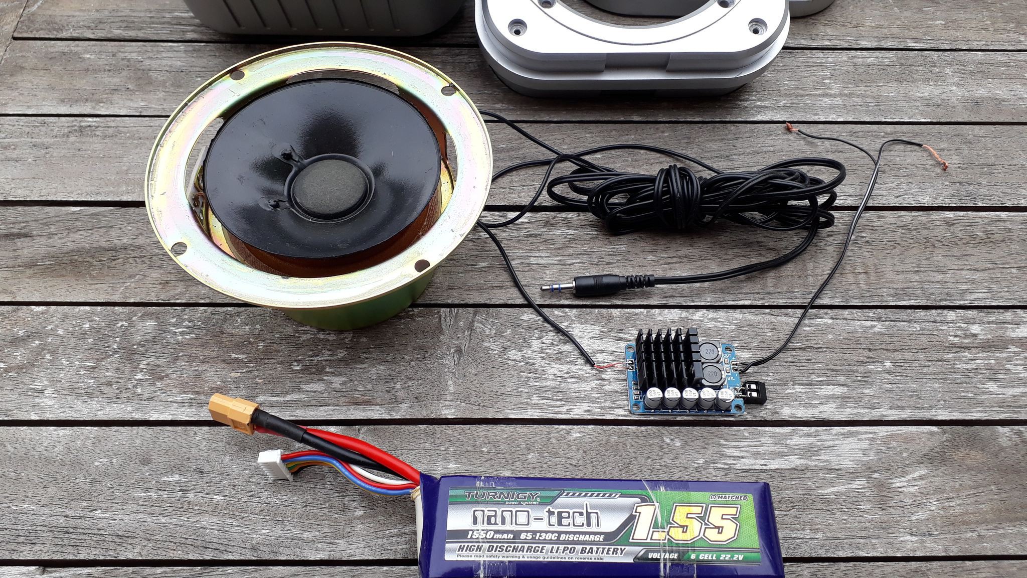
Repaired speaker Speaker repair is done. Was quite the easy process, even glue was included. Next thing will be to mount the amp and battery etc. Would love to add both into the case but there's not enough spcae for both...
---------- more ----------It's time!
Here's the first use-case for the new little board, which will really make use of all its features:
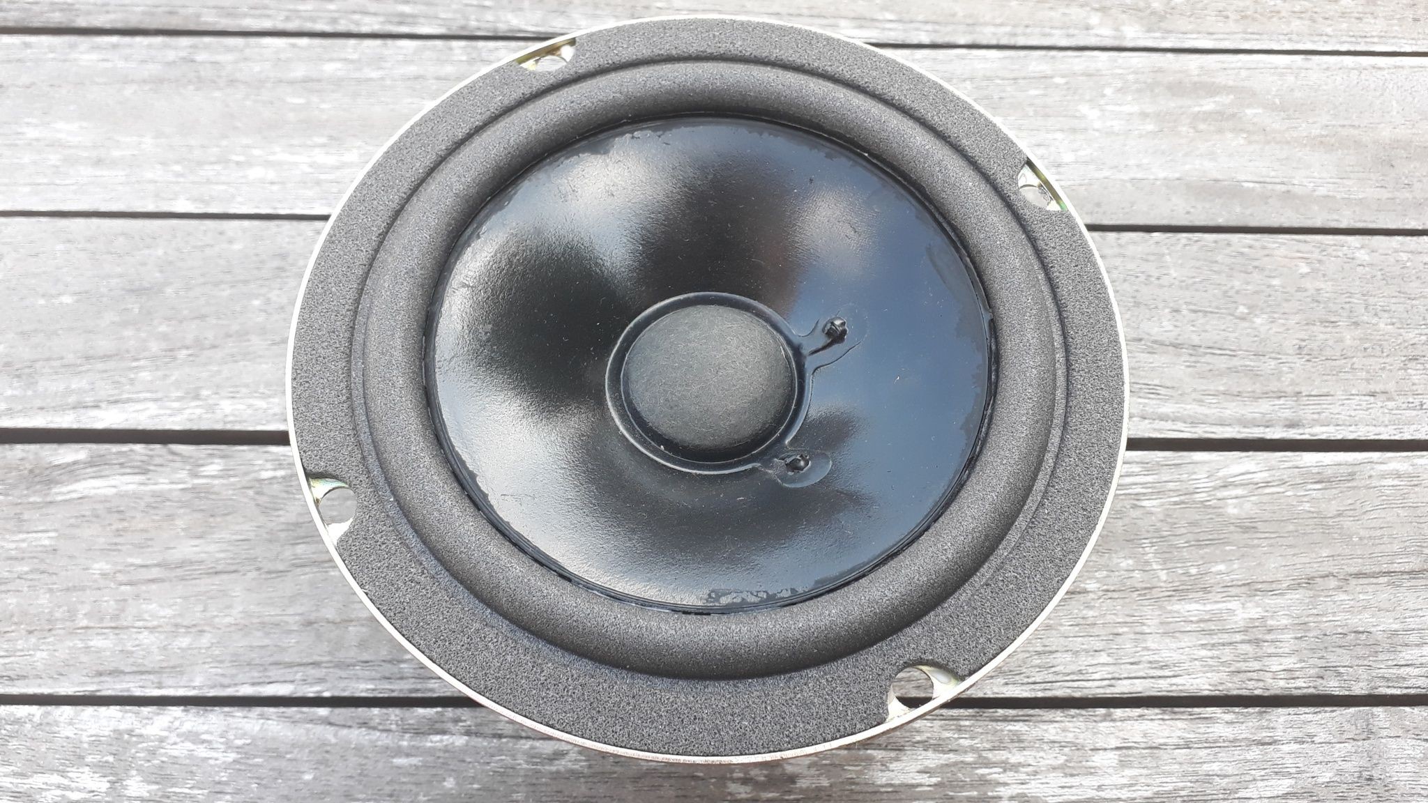
![A soon to be fixed JBL Control 1 speaker A soon to be fixed JBL Control 1 speaker]()
A soon to be fixed JBL Control 1 speaker ![]()
This sweet old JBL Control 1 speaker will be transformed into a(nother) mobile boom box. Those speakers are heavy and sturdy but they all suffer from the same illness: the suspension of the main woofer just crumbles away after 10 years or so.
I Already removed the old and ordered a new one.
The small TDA8932B class D amp was only 7.5€ on eBay and wow is that thing capable. Accepts 36V max and has no audible switch-on or off sound. Sweeeeeet! I glued a small heat sink to the chip anyway, gets pretty toasty! It has full thermal protection though...
Now why is my UVLO circuit perfect for this amp?
I like electronic music. Not really the EDM kind but the real stuff. Stuff like this :)
Now, with every bass kick, the amp draws much more power than in the more quiet parts, which results in voltage drops across the battery.
This is where the pre-set undervoltage dip-time comes in handy. It will be set to 5 to 10 seconds or so to keep the circuit from disconnecting the supply just because the battery dropped below the limit for a second or two!
The other settings will be according to the really "used" battery state: Cut-off at an early 3.0 or 2.9V and the cells to... well 6 because it's a 6 cell LiPo battery :)
-
10 – next iteration
07/22/2019 at 07:41 • 0 commentsUpdate:
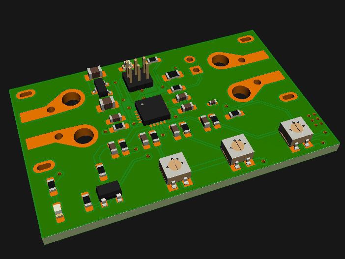
New board will look something like this. The above screenshot is fully routed and DRC'd. Should work :) Size is 25 x 40mm (1" x 1.6"). MOSFET and two diodes are on the bottom copper side. I'd love to get rid of the trimmer pots but then I'd loose all comfort which was a main goal of this project: using one board for all project-needs without the need for an PC to change settings...
---------- more ----------Where to go from here
So, I did a few tests with DC/DC buck regulators and "standard" LDO linear regulators. DC/DC has been very easy with the right board layout, ripple is not too much of a problem...
But there's two drawbacks which pushed me in the linear regulator direction again:
- higher current consumption in low current draw scenarios (major drawback)
- more expensive, more parts (minor drawback)
What is my solution?
I will use the cheap and durable (in my limited test samples at least) Nanjing Micro One Elec ME6203 regulator. It is a china brand, which means there's no chance getting it from Digikey or other major vendors, but this is a minor concern for me at this point. I just want my hand full of working boards :)
I will add an 5V6 zener diode at the output to clamp the 5V rail to a 6V maximum (which is including the zeners tolerances). The ME6203 shorts out at 20mA, heats up and survives this condition for hours.
My overall power requirement will be well under 5mA. The Attiny will be clocked at 1Mhz internal RC oscillator which is plenty for burst-reading 10 ADC values at 10Hz. Conversion time for the first reading is around 25µs and 13µs for the next reading.
A very interesting approach would be the Attiny1616: it has the internal capability to to burst-readings (up to 64) and give the average from that... See here for details!
When will the next set of boards be ready?
Soonish :)
-
09 – first DC/DC tests
07/04/2019 at 19:31 • 0 commentsUpdate – 2019-07-15
The ripple-measurement screenshots I originally posted below were done with the ground-wire-alligator-clip-method and not the correct direct-connection method. See this Application note by Analog [p.5] for more details how to do it correctly. Analog doesn't call it "Incorrect Ground Loop Method" for no reason...
Measuring this way (and setting the probe to 1x = no amplification) the ripple reduces to the more reasonable 30mVpp I mentioned in my updated log below.
Update – 2019-07-10
Using the DC/DC buck converter with nearly 30mVpp ripple the ADC readings by my Attiny861A test board are always within 0.05V of "jitter" between readings (each reading is an average of 10 single readings).
So, the circuit seems to work just fine. Problematic thing is the "no load"-current of nearly 0.55mA which is too much drain on my projects batteries for my taste.
We'll see where it goes from here...
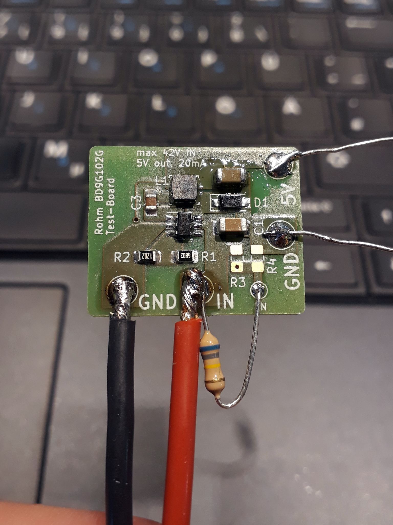
---------- more ----------Today, 7 days after ordering, PCBs and parts arrived in my mailbox.
Build process
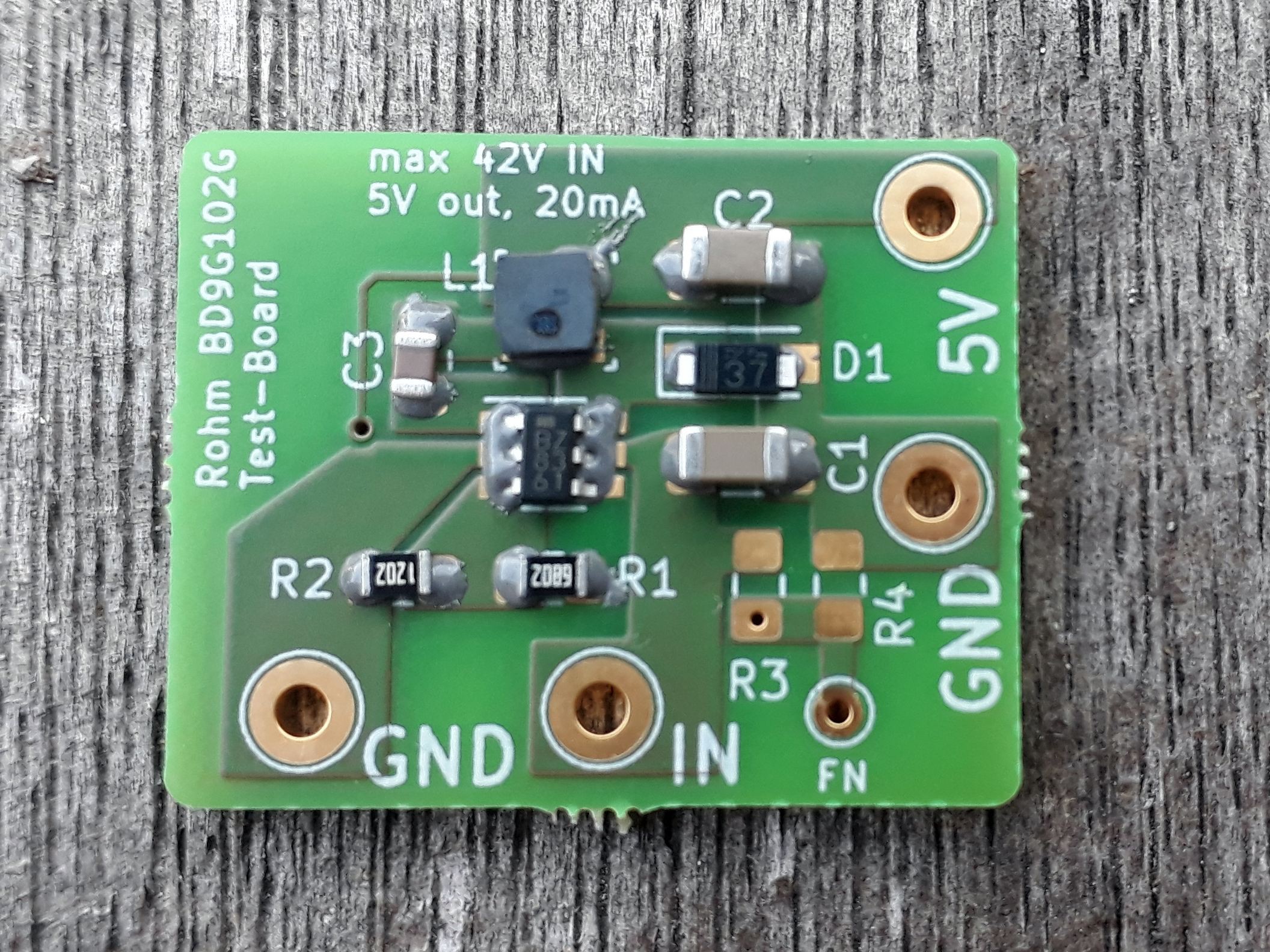
![]()
PCB, solderpaste, parts ![]()
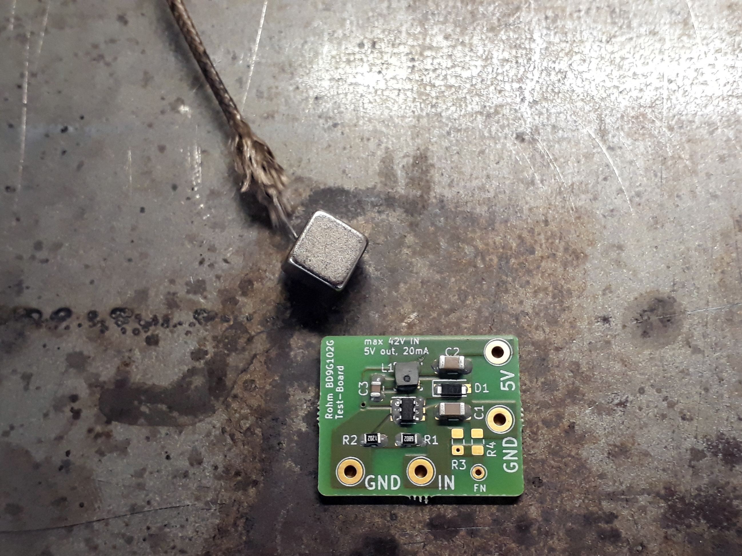
PCB ready to reflow on a steel plate. ![]()
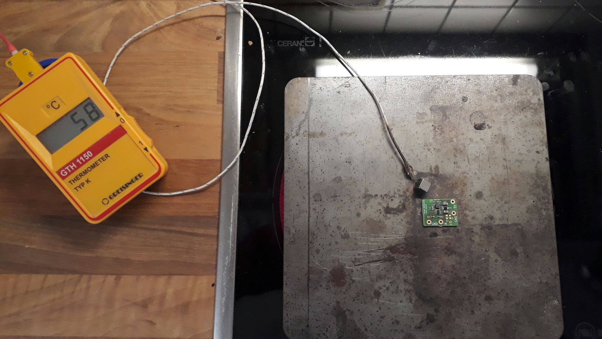
keeping an eye on temperature. solder starts to flow at around 170°C ![]()
resistor is to keep enable HIGH, flux around capacitor is becuase I needed to touch it up... Measurements
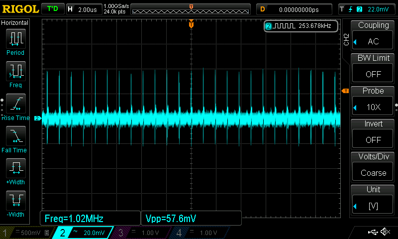
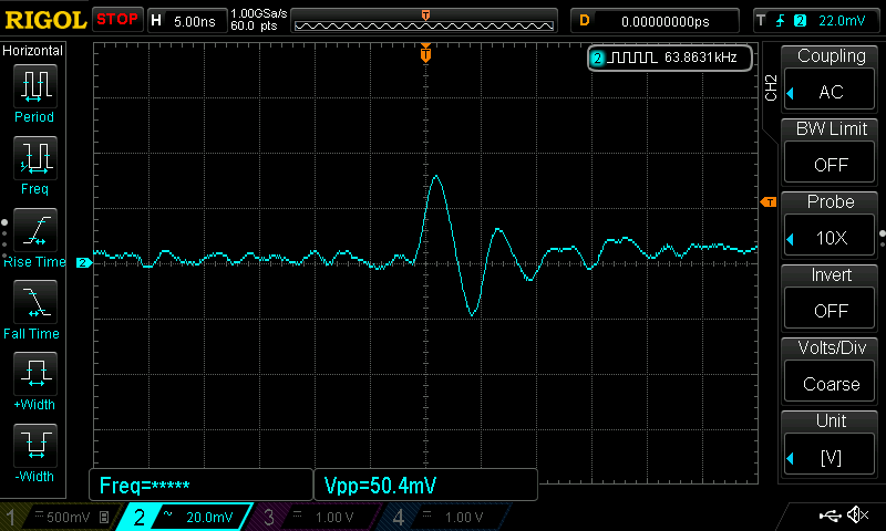
nearly 60mV peak to peak... this is at 10mA out If I remember correctly the peaks are the switching noise from the regulator/coil. This makes sense as it it exactly the 1Mhz switching frequency of the regulator.
a single peak -
08 – thoughts about linear regulators
06/28/2019 at 07:15 • 4 commentsThere are some laws that just can't be bent. Ohms law is one of those. It dictates the law of conservation of power, which means: P_in = P_out.
So, you can't just expect the small linear regulator in a SOT23-5 case to convert 40V to 5V and 100mA without getting hot.
The power dissipated by the regulator will be:
The biggest "drivers" here are the input voltage and the current at the output. I need at least 10mA to guarantee safe operation while switching the MOSFET. The ground current usually is in the range of 100µA.
With a full 8S (yes, I want to extend to this cell-count) battery at 33.6V this means around 0.3W of power which the regulator needs to get rid off.
SOT-23 cases feature very bad thermal design with around 170°C heat-up per W dissipated power. That's the "Junction to ambient thermal resistance" value in the datasheet. The value is so high because the plastic case has no metallic pad which could transfer the heat into the PCB much more efficiently.
So, 0.3W x 170°C = 51°C heat on top of the ambient temperature. This would be okay on paper but it creates a hot-spot on the PCB which spreads to other parts which have a drift with temperature...
The paper linked above has good design techniques for this style of case. I'll definitely try that anyway as the DC/DC chips I want to try are in that case too. Richtek has some good info on this as well. -
07 – new linear regulator tests
06/26/2019 at 19:30 • 5 commentsUpdate 2019-07-15
I tested two of the regulators. Both work quite well and didn't release the magic smoke yet. Even after the the repeated inrush-current tests (repeatedly connecting the fully charged 6S lipo battery) with the load connected.
The MD7350H does indeed use the full 3% output voltage tolerance stated in the datasheet and is my least favorite part.
The much smaller ME6203 works perfectly up to 38V and limits itself when short-circuited. It puts out perfect 5.00V under up to 20mA load and has a smaller footprint than the MD7350H. Using bigger PCB traces on all three pins will wick away enough heat to ensure proper cooling at 5V/10mA out (max).
At 2.7µA current consumption with no load (µC in power down state) it's well within what I need for low battery discharge when the circuit cuts the connection. I think my next set of PCBs will use this regulator!
The SY6345's are still in their anti-static bag and will be tested next.
---------- more ----------Had to order at LCSC anyway... So why not search for chinese brand regulators again?
I ordered the following chips for further tests:
- Nanjing Micro One Elec: ME6203
- 40V max., 5V/100mA (SOT-23-3)
- always on, around 3µA quiescent current
- Silergy Corp: SY6345
- around 6µA quiescent current, around 2µA in shutdown mode
- 40V max., adj. output (resistor divider)
- EN function
- Shanghai Mingda Microelectronics: MD7350H
- 40V max.
- always on, around 3µA quiescent current
We'll see how they work in my application!
- Nanjing Micro One Elec: ME6203
Universal undervoltage lockout up to 34V input
Feature-packed over-discharge protection. Set the cell-count, minimum cell voltage and dip-time below threshold. Fully hackable!
 Jan
Jan

